Solar PV Array-Fed Water Pumping System Using Zeta Converter
based Closed-Loop Control of BLDC Motor Drive
Kilana Sagar Santosh & M. Vaidehi
M-tech Student Scholar Department of Electrical & Electronics Engineering, BABA Institute of Technology and Sciences Visakhapatnam (Dt); A.P, India.
E-mail: [email protected]
Assistant Professor Department of Electrical & Electronics Engineering, BABA Institute of Technology and Sciences Visakhapatnam (Dt); A.P, India.
E-mail: [email protected]
Abstract: This paper proposes a solar photovoltaic (SPV) array fed water pumping system utilizing a zeta converter as an intermediate DC-DC converter in order to extract the maximum available power from the SPV array. Controlling the zeta converter in an intelligent manner through the incremental conductance maximum power point tracking (INC-MPPT) algorithm offers the soft starting of the brushless DC (BLDC) motor employed to drive a centrifugal water pump coupled to its shaft. Soft starting i.e. the reduced current starting inhibits the harmful effect of the high starting current on the windings of the BLDC motor. A fundamental frequency switching of the voltage source inverter (VSI) is accomplished by the electronic commutation of the BLDC motor, thereby avoiding the VSI losses occurred owing to the high frequency switching. A new design approach for the low valued DC link capacitor of VSI is proposed. The proposed water pumping system is designed and modeled such that the performance is not affected even under the dynamic conditions. Suitability of the proposed system under dynamic conditions is demonstrated by the simulation results using MATLAB/Simulink software.
Key words: Brushless dc (BLDC) motor, incremental conductance maximum power point tracking (INC-MPPT), solar photovoltaic (SPV) array, voltage-source inverter (VSI), water pump, zeta converter
I. Introduction
Severe environmental protection regulations, shortage of fossil fuels and eternal energy from the sun have motivated there searchers towards the solar photovoltaic (SPV) array generated electrical power for various applications [1]. Water pumping is receiving wide attention nowadays amongst all the applications of SPV array. To enhance the efficiency of SPV array and hence the whole system regardless of the operating conditions, it becomes essential to operate SPV array at its maximum power point by means of a maximum power point tracking (MPPT)algorithm [2-4]. Various DC-DC converters have been already employed to accomplish this action of MPPT. Nevertheless, a Zeta converter [5 -9] based MPPT is still unexplored in any kind of SPV array based applications. An incremental conductance (INC) MPPT algorithm [2] is used in this work in order to generate an optimum value of duty cycle for the IGBT
(Insulated Gate Bipolar Transistor) switch of Zeta converter such that the SPV array is constrained to operate at its MPP. Various configuration of Zeta converters such as self-lift circuit, re-lift circuit, triple-lift circuit and quadruple-lift circuit using voltage lift(VL) technique have been reported in afore mentioned topologies have high voltage transfer gain but at the cost of increased number of components and switching devices. Therefore, these topologies of Zeta converter do not suit the proposed water pumping system.
The PV inverters dedicated to the small PV plants must be characterized by a large range for the input voltage in order to accept different configurations of the PV field. This capability is assured by adopting inverters based on a double stage architecture where the first stage, which usually is a dc/dc converter, can be used to adapt the PV array voltage in order to meet the requirements of the dc/ac second stage, which is used to supply an ac load or to inject the produced power into the grid. This configuration is effective also in terms of controllability because the first stage can be devoted to track the maximum power from the PV array, while the second stage is used to produce ac current with low Total Harmonic Distortion (THD).
proposed to a solar PV array fed DC link capacitor free BLDC motor.
The permanent magnet brushless DC (BLDC) motor is employed to drive a centrifugal water pump coupled to its shaft. The BLDC motor is selected because of its merits [7,9]useful for the development of suitable water pumping system. This electronically commutated BLDC motor [9-11] is supplied by a voltage source inverter (VSI) which is operated by fundamental frequency switching resulting in low switching losses [12-15]. Suitability of the proposed SPV array fed water pumping system subjected to various operating and environmental conditions is demonstrated by satisfactory simulated results using MATLAB/Simulink environment.
The existing literature exploring SPV array-based BLDC motor-driven water pump is array-based on a configuration shown in Fig.1. A dc–dc converter is used for MPPT of an SPV array as usual. Two phase currents are sensed along with Hall signals feedback for control of BLDC motor, resulting in an increased cost. The additional control scheme causes increased cost and complexity, which is required to control the speed of BLDC motor. Moreover, usually a voltage-source inverter(VSI) is operated with high-frequency PWM pulses, resulting in an increased switching loss and hence the reduced efficiency.
Fig.1. Conventional SPV-fed BLDC motor-driven water pumping system
II. CONFIGURATION OF PROPOSED SYSTEM
The structure of proposed SPV array-fed BLDC motor driven water pumping system employing a zeta converter is shown in Fig.3.2. The proposed system consists of (left to right) an SPV array, a zeta converter, a VSI, a BLDC motor, and a water pump. The BLDC motor has an inbuilt encoder. The pulse generator is used to operate the zeta converter. A step-by-step operation of proposed system is elaborated in Section III in detail.
III. OPERATION OF PROPOSEDSYSTEM
The SPV array generates the electrical power demanded by the motor-pump. This electrical power is fed to the motor pump via a zeta converter and a VSI. The SPV array appears as a power source for the zeta converter as shown in Fig.2. Ideally, the same amount of power is transferred at the output of zeta converter which appears as an input source for the VSI. In practice, due to the various losses associated with a dc–dc converter [23], slightly less amount of power is transferred to feed the VSI. The pulse generator generates, through INCMPPT algorithm, switching pulses for insulated gate bipolar transistor (IGBT) switch of the zeta converter. The INC-MPPT algorithm uses voltage and current as feedback from SPV array and generates an optimum value of duty cycle. Further, it generates actual switching pulse by comparing the duty cycle with a high-frequency carrier wave. In this way, the maximum power extraction and hence the efficiency optimization of the SPV array is accomplished.
The VSI, converting dc output from a zeta converter into ac, feeds the BLDC motor to drive a water pump coupled to its shaft. The VSI is operated in fundamental frequency switching through an electronic commutation of BLDC motor assisted by its built-in encoder. The high frequency switching losses are thereby eliminated, contributing in an increased efficiency of proposed water pumping system.
Fig.2. Proposed SPV-zeta converter-fed BLDC motor drive for water pump
IV. DESIGN OF PROPOSEDSYSTEM
SPV array, zeta converter, and water pump are described as follows.
A. Design of SPV Array
As per above discussion, the practical converters are associated with various power losses. In addition, the performance of BLDC motor-pump is influenced by associated mechanical and electrical losses. To compensate these losses, the size of SPV array is selected with slightly more peak power capacity to ensure the satisfactory operation regardless of power losses. Therefore, the SPV array of peak power capacity of Pmpp=3.4 kW under STC (STC: 1000 W/m2, 25oC,AM
1.5), slightly more than demanded by the motor-pump is selected and its parameters are designed accordingly. Solar World make Sun module Plus SW 280 mono [24] SPV module is selected to design the SPV array of an appropriate size. Electrical specifications of this module are listed in Table 3.1 and numbers of modules required to connect in series/parallel are estimated by selecting the voltage of SPV array at MPP under STC as Vmpp=
187.2V.
TABLE1
Specifications of Sun module plus SW 280monoSPV Module
The current of SPV array at MPPImppis estimated as
(1) The numbers of modules required to connect in series are as follows:
(2) The numbers of modules required to connect in parallel areas follows:
(3) Connecting six modules in series, having two strings in parallel, an SPV array of required size is designed for the proposed system.
B. Design of Zeta Converter
The zeta converter is the next stage to the SPV array. Its design consists of an estimation of various components such as input inductorL1, output inductor L2,
and intermediate capacitor C1. These components are
designed such that the zeta converter always operates in CCM resulting in reduced stress on its components and devices. An estimation of the duty cycle D initiates the design of zeta converter which is estimated as [6]
(4) Where Vdc is an average value of output voltage
of the zeta converter (dc link voltage of VSI) equal to the dc voltage rating of the BLDC motor.
An average current flowing through the dc link of the VSI Idc is estimated as
(5) Then,L1, L2, andC1 are estimated as
(6)
(7)
(8) Where fsw is the switching frequency of IGBT
switch of the zeta converter;ΔIL1is the amount of
permitted ripple in the current flowing
throughL1,sameasIL1=Impp; ΔIL2is the amount of permitted
ripple in the current flowing throughL2,same as IL2=Idc;
ΔVC1 is permitted ripple in the
voltageacrossC1,sameasVC1=Vdc.
C. Estimation of DC-Link Capacitor of VSI
further used to estimate the values of their corresponding capacitors. Out of these two estimated capacitors, larger one is selected to assure a satisfactory operation of proposed system even under the minimum solar irradiance level.
The fundamental output frequency of VSI corresponding to the rated speed of BLDC motor ωrated is
estimated as
(9) The fundamental output frequency of the VSI corresponding to the minimum speed of the BLDC motor essentially required to pump the water(N= 1100r/min) ωmin is estimated as
(10) Where frated and fmin are fundamental frequencies
of output voltage of VSI corresponding to a rated speed and a minimum speed of BLDC motor essentially required to pump the water, respectively, in Hz; Nrated is
rated speed of the BLDC motor; Pis a number of poles in the BLDC motor.
The value of dc link capacitor of VSI at ωratedis as follows:
(11) Similarly, a value of dc link capacitor of VSI at ωminis as
follows:
(12) Where ΔVdc is an amount of permitted ripple in
voltage across dc-link capacitorC2.Finally, C2= 410µF is
selected to design the dc-link capacitor.
D Design of Water Pump
To estimate the proportionality constant K for the selected water pump, its power–speed characteristics [26], [27] issued as
(13) Where P=2.89 kW is rated power developed by the BLDC motor and ωr is rated mechanical speed of the
rotor (3000r/min) in rad/s.
A water pump with these data is selected for proposed system.
Fig.3. Illustration of INC-MPPT with SPV array Ppv−vpv
characteristics. TABLE.2
Switching States for Electronic Commutation of BLDC Motor
V. CONTROL OFPROPOSEDSYSTEM
The proposed system is controlled in two stages. These two control techniques, viz., MPPT and electronic commutation, are discussed as follows.
A. INC-MPPT Algorithm
𝑑𝑃𝑝𝑣
𝑑𝑉𝑝𝑣
=
0
;
at mpp
𝑑𝑃𝑝𝑣
𝑑𝑉𝑝𝑣
>0
;left of mpp
𝑑𝑃𝑝𝑣
𝑑𝑉𝑝𝑣
< 0; right of mpp
(14) Since
(15) Therefore, (14) is rewritten as
(16) Thus, based on the relation between INC and instantaneous conductance, the controller decides the direction of perturbation as shown in Fig. 3, and increases/decreases the duty cycle accordingly. For instance, on the right of MPP, the duty cycle is increased with a fixed perturbation size until the direction reverses. Ideally, the perturbation stops once the operating point reaches the MPP. However, in practice, operating point oscillates around the MPP.
As the perturbation size reduces, the controller takes more time to track the MPP of SPV array. An intellectual agreement between the tracking time and the perturbation size is held to fulfill the objectives of MPPT and soft starting of BLDC motor. In order to achieve soft starting, the initial value of duty cycle is set as zero. In
addition, an optimum value of perturbation
size(ΔD=0.001)is selected, which contributes to soft starting and also minimizes oscillations around the MPP.
B. Electronic Commutation of BLDC Motor
The BLDC motor is controlled using a VSI operated through an electronic commutation of BLDC
motor. An electronic commutation of BLDC motor stands for commutating the currents flowing through its windings in a predefined sequence using decoder logic. It symmetrically places the dc input current at the center of each phase voltage for 120o. Six switching pulses are
generated as per the various possible combinations of three Hall-effect signals. These three Hall-effect signals are produced by an inbuilt encoder according to the rotor position.
A particular combination of Hall-effect signals is produced for each specific range of rotor position at an interval of 60o[5], [6]. The generation of six switching
states with the estimation of rotor position is tabularized in Table II. It is perceptible that only two switches conduct at a time, resulting in 120oconduction mode of
operation of VSI and hence the reduced conduction losses. Besides this, the electronic commutation provides fundamental frequency switching of the VSI; hence, losses associated with high-frequency PWM switching are eliminated. A motor power company makes BLDC motor[28] with inbuilt encoder is selected for proposed system and its detailed specifications are given in the Appendixes.
VI. CLOSED LOOP SPEED CONTROL OF BLDC MOTOR
In the sensored BLDC drive, hall sensors or a shaft encoder is used to obtain the rotor position information. The drive control system consists of an outer speed loop for speed control and an inner current loop for current control. Conventionally three separate current sensors are used to measure the phase currents. But here only one current sensor is used, which is placed on the DC link.
A. Speed control
The speed control block uses a Proportional Integral (PI) controller. A PI controller attempts to correct the error between a measured process variable and desired set point by calculating and then outputting a corrective action that can adjust the process accordingly. The PI controller calculation involves two separate modes the proportional mode and the integral mode. The proportional mode determine the reaction to the current error, integral mode determines there action based recent error. The weighted sum of the two mode output as corrective action for the control element. The PI controller is widely used in the industry due to its ease in design and simple structure. The PI controller algorithm can be implemented as
Here the input to speed controller is the speed error. The output of the controller is considered as a reference torque. A limit is put on the speed controller output depending on permissible maximum winding currents.
VII. MATLAB/SIMULATION RESULTS
Fig. 4 Matlab/Simulink circuit of Starting and steady-state performances of the proposed SPV array based zeta converter-fed BLDC motor drive
for water pump
(a)
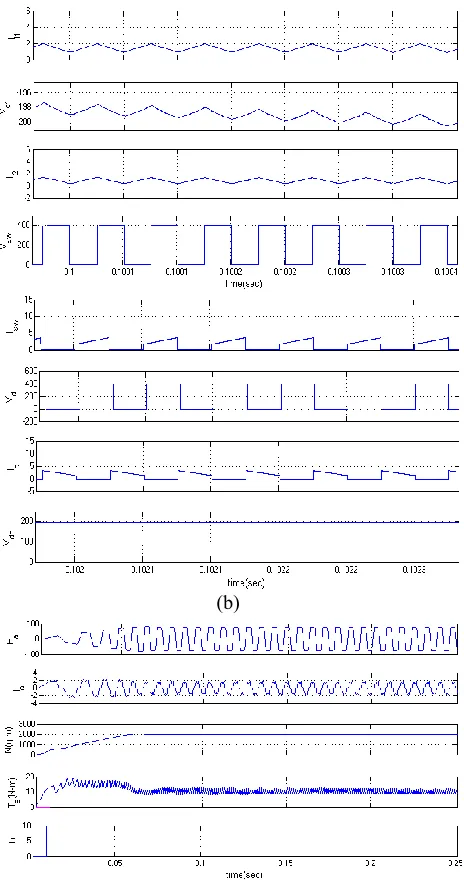
(b)
(c)
Fig.5Starting and steady-state performances of the proposed SPV array based zeta converter-fed BLDC motor drive for water pump. (a) SPV
Fig.6 Matlab/Simulink circuit for Dynamic performance of SPV array-based zeta converter-fed BLDC motor drive for water pump
(a)
(b)
(c)
Fig.7 Dynamic performances of the proposed SPV array-based zeta converter-fed BLDC motor drive for water pump. (a) SPV array variables. (b) Zeta converter variables. (c) BLDC motor-pump variables.
Fig.9 Speed.
Fig.10 Torque.
Fig.11 Stator current and emf.
VIII CONCLUSION
A solar photovoltaic array fed Zeta converter based BLDC motor has been proposed to drive water-pumping system. The proposed system has been designed, modeled and simulated using MATLAB along with its Simulink and simpower system toolboxes. Simulated results have demonstrated the suitability of proposed water pumping system. SPV array has been properly sized such that system performance is not influenced by the variation in atmospheric conditions and the associated losses and maximum switch utilization of Zeta converter is achieved. Zeta converter has been operated in CCM in
order to reduce the stress on power devices. Operating the VSI in conduction mode with fundamental frequency switching eliminates the losses caused by high frequency switching operation. Stable operations of motor-pump system and safe starting of BLDC motor are other important features of the proposed system.
REFERENCES
[1] M. Uno and A. Kukita, ―Single-switch voltage equalizer using multistacked buck–boost converters for partially-shaded photovoltaic modules,‖IEEE Trans. Power Electron., vol. 30, no. 6, pp. 3091– 3105, Jun.2015.
[2] R. Arulmurugan and N. Suthanthiravanitha, ―Model and design of afuzzy-based Hopfield NN
tracking controller for standalone PV
applications,‖Elect. Power Syst. Res., vol. 120, pp. 184–193, Mar. 2015.
[3] S. Satapathy, K. M. Dash, and B. C. Babu, ―Variable step size MPPTalgorithm for photo voltaic array using zeta converter—A comparativeanalysis,‖ inProc. Students Conf. Eng. Syst. (SCES), Apr. 12– 14, 2013,pp. 1–6.
[4] R. Kumar and B. Singh, ―BLDC motor driven solar PV array fed waterpumping system employing zeta converter,‖ inProc. 6th IEEE India Int.Conf. Power Electron. (IICPE), Dec. 8–10, 2014, pp. 1–6. [5] B. Singh, V. Bist, A. Chandra, and K. Al-Haddad, ―Power factor correction in bridgeless-Luo converter-fed BLDC motor drive,‖ IEEE Trans.Ind. Appl., vol. 51, no. 2, pp. 1179–1188, Mar./Apr. 2015.
[6] B. Singh and V. Bist, ―Power quality improvements in a zeta converterfor brushless dc motor drives,‖ IET Sci. Meas. Technol., vol. 9, no. 3,pp. 351–361, May 2015.
[7] R. F. Coelho, W. M. dos Santos, and D. C. Martins, ―Influence of powerconverters on PV maximum power point tracking efficiency,‖ inProc.10th IEEE/IAS Int. Conf. Ind. Appl. (INDUSCON), Nov. 5–7, 2012,pp. 1–8.
[8] M. A. Elgendy, B. Zahawi, and D. J. Atkinson, ―Assessment of the incremental conductance
maximum power point tracking
algorithm,‖IEEETrans. Sustain. Energy, vol. 4, no. 1, pp. 108–117, Jan. 2013.
photovoltaic generator,‖IEEE Trans. Ind. Electron., vol. 62, no. 9, pp. 5776–5785, Sep. 2015.
[10] R. Kumar and B. Singh, ―Buck–boost converter fed BLDC motor drivefor solar PV array based water pumping,‖ inProc. IEEE Int. Conf. PowerElectron. Drives Energy Syst. (PEDES), Dec. 16–19, 2014, pp. 1–6.
[11] A. H. El Khateb, N. Abd. Rahim, J. Selvaraj, and B. W. Williams, ―DCto-dc converter with low input current ripple for maximum photovoltaicpower extraction,‖IEEE Trans. Ind. Electron., vol. 62, no. 4, pp. 2246–2256, Apr. 2015.
[12] D. D. C. Lu and Q. N. Nguyen, ―A photovoltaic panel emulator usinga buck–boost dc/dc converter and a low cost micro-controller,‖SolarEnergy, vol. 86, no. 5, pp. 1477–1484, May 2012.
[13] Z. Xuesong, S. Daichun, M. Youjie, and C. Deshu, ―The simulationand design for MPPT of PV system based on incremental conductancemethod,‖ inProc. WASE Int. Conf. Inf. Eng. (ICIE), Aug. 14– 15, 2010,vol. 2, pp. 314–317.
[14] A. R. Reisi, M. H. Moradi, and S. Jamasb, ―Classification and comparisonf maximum power point tracking techniques for photovoltaic system: Areview,‖Renew. Sustain. Energy Rev., vol. 19, pp. 433–443, Mar. 2013.
[15] B. Bendib, H. Belmili, and F. Krim, ―A survey of the most used MPPTmethods: Conventional and
advanced algorithms applied for