R E S E A R C H
Open Access
Characterization of path loss and absorption
for a wireless radio frequency link between an
in-body endoscopy capsule and a receiver
outside the body
Karen Lopez-Linares Roman
†, Günter Vermeeren
†, Arno Thielens, Wout Joseph
*and Luc Martens
Abstract
Physical-layer characterization is important for design of in-to-out body communication for wireless body area networks (WBANs). This paper numerically investigates the path loss and absorption of an in-to-out body radio frequency (RF) wireless link between an endoscopy capsule and a receiver outside the body using a 3D electromagnetic solver. A spiral antenna in the endoscopy capsule is tuned to operate in the Medical Implant Communication Service (MICS) band at 402 MHz, accounting for the properties of the human body. The influence of misalignment, rotation of the capsule, and three different human models are investigated. Semi-empirical path loss models for various homogeneous tissues and 3D realistic human body models are provided for manufacturers to evaluate the performance of in-body to out-body WBAN systems. The specific absorption rate (SAR) in homogeneous and heterogeneous body models is characterized and compliance is investigated.
Keywords: In-to-out body; Heterogeneous human body model; Wireless body area network; Path loss; Propagation channel; Endoscopy capsule
Introduction
A wireless body area network (WBAN) connects nodes that are situated on or in the body of a person. Applica-tions of WBANs include medicine and health care, sports, and multimedia. As it facilitates movement among users, it has brought about a revolutionary change in patient monitoring and healthcare facilities. Active implants placed within the human body lead to better and faster diagnosis, thus, improving the quality of life of the patient. The development of an endoscopy capsule system enables the examination of areas of the small intestine that cannot be seen by other types of endoscopy. The benefits of the capsule endoscopy in terms of a better diagnosis are obvi-ous. Also, the patient’s comfort improves, as there are no wires or tubes involved in the procedure.
*Correspondence: [email protected]
†Equal contributors
Department of Information Technology, Ghent University/iMinds, Gaston Crommenlaan 8 Box 201, Ghent 9050, Belgium
The characterization of the physical layer of the net-work is an important step in the development of a WBAN. A lot of studies investigated on-body propagation [1-11]. Less literature is available on modeling of propagation loss within or in-to-out the human body [12-17] and often the focus is on 2.4 GHz. A path loss (PL) model for in-body wireless implants (biocompatible implantable antennas) is proposed in [12]. Scenarios for channel modeling for an endoscopy application are proposed in [14]. In [13] and [18] similar investigations were presented, but both of them proposed the 2.4 GHz frequency band, which led to a smaller antenna. In addition, in-body to in-body com-munication is examined. The influence of different tissues at various frequencies is characterized for an in-to-out channel in [19], but the antenna design was not speci-fied. A multi-implant scenario at 2.4 GHz is investigated in [20] using insulated dipole antennas for specific locations such as the liver, heart, spleen, and the kidneys. A spi-ral antenna at 450 MHz for ingestible capsule endoscope systems is designed in [21].
The objective of this paper is to investigate numeri-cally the PL of an in-to-out body radio frequency (RF) wireless link between an endoscopy capsule and a half-wavelength dipole (reference receiver) outside the body using a 3D electromagnetic solver, applying the finite dif-ference time domain (FDTD) method. This study focusses on the 402 to 405 MHz Medical Implant Communication Service (MICS) band. The spiral antenna for an endoscopy capsule operating at 450 MHz proposed by [21] is selected as the transmitter and tuned to operate at 402 MHz by changing its dimensions. This spiral antenna fits inside a capsule and is experimentally validated in a human phan-tom and a pig under general anesthesia. Therefore, we selected this antenna for our propagation analysis. Both antennas are dimensioned with the FDTD simulation plat-form SEMCAD-X. Path loss for the in-to-out channel and the specific absorption rate (SAR) are investigated for homogeneous and heterogeneous tissues of three human models, namely, an adult, an obese adult, and a child. The influence of the dielectric properties of the tissue on the PL is evaluated and compliance of the electro-magnetic absorption with the international guidelines of the International Commission on Non-Ionizing Radiation Protection (ICNIRP) [22] is evaluated for the maximum allowed radiated power.
The analysis of this research can be used by manufac-turers to evaluate the performance of in-body to out-body WBAN systems and to carry out link budget calcula-tions, since it is difficult for them to test their systems on actual humans. This research also enables to better esti-mate the energy consumption of the endoscopy capsule and thus, the battery lifetime, which is limited due to the small size of the pills. Another application of the mod-els of this paper is cross-layer design, where the proposed models are used to evaluate communication protocols for WBANs and the energy consumption in short-range wireless networks [6].
Frequency selection
The wireless connection between the devices of a WBAN can occur at different frequencies. Most published models use the industrial, scientific, and medical (ISM) frequency bands or UWB (ultra-wideband). Among these, the most commonly used frequencies in medical communications are 402 MHz, 868 MHz, and 2.4 GHz. The choice of the optimum frequency is an important factor taking into account attenuation, tissue conductivity, and also antenna size and orientation, which can affect not only radia-tion inside the body but can also determine the optimum distance of which good performance can be achieved in the surrounding environment. The MICS band is a licensed band used for implant communication and has the same frequency range (402 to 405 MHz) in most countries [23].
The MICS band does not support high data rate appli-cations. The ISM 2.4 GHz band supports higher data rate applications and is available worldwide. However, there are high chances of interference as many wireless devices operate at ISM band and a higher attenuation in the body occurs due to the higher frequency. This results in a need to increase the transmitting power, which is a disadvantage in cases where the antenna is embedded within the human body, leading to higher power con-sumption and possible non-compliance with international exposure guidelines [22]. Thus, MICS is a lower power frequency band, with less risk to encounter interferences. It allows longer communication links because the atten-uation is lower. A disadvantage is that the size of the antennas increases. According to the authors’ knowledge, there is only a small amount of studies about in-to-out body propagation for this band.
Method
Configurations
Homogeneous tissues
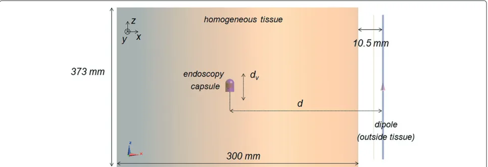
The path loss is investigated for three different tissues using the 3D FDTD solver SEMCAD-X at 402 MHz: mus-cle tissue (permittivity r = 57.1, conductivity σ = 0.8 S/m), skin tissue (r=46.7,σ =0.69 S/m), and esoph-agus tissue (r =67.5,σ =1 S/m) are considered. These represent relevant tissues for the endoscopy configuration [14]. The simulation settings are the same in all the cases. Harmonic simulations at 402 MHz are run with a simula-tion time of 14 periods. UPML (uniaxial perfectly matched layer) boundaries terminate the simulation domain and absorb 95% of the incident power. The padding is set to λ/4. A maximum grid step of 2 mm is applied inside the body. Aligned and misaligned configurations and rotation of the transmitting spiral antenna in the capsule are inves-tigated. Figure 1 shows the investigated configuration.
Heterogeneous phantom models
Three heterogeneous models are investigated: a 6-year-old boy (denoted Thelonius), an adult man (denoted Duke), and an obese adult man (denoted Fats) [24]. The Virtual Population models are based on magnetic res-onance images (MRI) of healthy volunteers. The tissue properties for the frequency of 402 MHz are assigned from Gabriel’s database [25] and a maximum grid step in the body of 2 mm is used.
Figure 1Configuration for the path loss analysis between capsule in the homogeneous tissue and receiver outside.d= antenna separation,dv= vertical displacement.
the body next to the arm in the case of the adult man and the obese man (Figure 2a) and at 13.5 cm in front of the body for the child model, at the height of the large intes-tine (Figure 2b), since most of the points of the digestive tract are located there.
Positions along the tract through the pharynx, the esophagus, the stomach lumen, and the small and large intestines lumen are selected with separations of 20 mm
Figure 2Configuration: locations of endoscopy capsule along digestive tract in realistic human body models.(a)Adult man Duke.(b)6-Year-old boy Thelonius. Squares indicate investigated positions of the capsule.
in thez-direction, while thex- andy-separation is 22 mm in the large intestine and 20 mm in the stomach and the small intestine. The spiral antenna is placed in every selected position as indicated in Figure 2a,b ((a) for adult and (b) for child). Figure 3 shows Fats and the loca-tions of the endoscopy capsule. The files are run using very high (99.9%) absorbing boundaries and a padding ofλ/4.
Antenna dimensioning
In this paper, it is not the goal to design suitable in-body antennas but to characterize the propagation from in-to-out the body. As a receiving antenna in-to-outside the body, a half-wavelength dipole is selected. The free-space dipole is modeled and tuned to resonate at 402 MHz. The thick-ness of the perfect electric conductor (PEC) structures is set at 2 mm and the gap is 1 mm. With respect to the transmitting antenna selection inside the body, PIFA (planar inverted-F antenna), dual-band microstrip patch antennas, and spiral antennas are often used for medical applications. In general, PIFA antennas are employed in artificial cardiac pacemakers and difficult to fit inside a pill. The size of the antenna is a factor of importance at 402 MHz. The spiral antenna [21] is the smallest among the different options and therefore it is selected for the investigation.
Spiral antenna in capsule
Figure 3Fats, a 37-year-old obese model (120 kg) of the Virtual Population and locations of endoscopy capsule.
The lengthLis an important parameter in the design of the spiral because it determines the resonance frequency. In addition, the spiral has to fit in the capsule. In this case, an antenna with 4.98-mm radius is modeled.
The thickness of the shell is 0.25 mm. The ground plane has a radius of 5 mm and a height of 0.5 mm. The capsule is closed at the bottom by a circular Ultem sheet with a thickness of 0.5 mm.
The influence of the (i) height and (ii) the length of the spiral, (iii) the effect of the gap between the antenna and the ground plane on the radiation characteristics (reso-nance frequency fres andS11 with respect to 50 ) are investigated, as well as (iv) the robustness of the spiral when immersed in different tissues. Frequency settings for performing broadband simulations in the FDTD sim-ulation platform are as follows: a central frequency of 402 MHz and a bandwidth of 0.4 GHz. In this way, the influence of the geometric parameters (mentioned above) is characterized. Based on the above parametric studies, dimensions for optimal antenna characteristics for the
Figure 4Capsule with spiral antenna and dielectric containers tuned to 402 MHz [21].
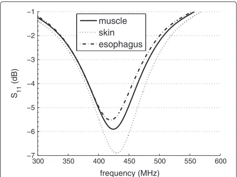
spiral antenna of the endoscopy capsule are selected. The parameters for the spiral antenna configuration used in this paper are listed in Table 1. Note that the antenna is not a very good radiator. TheS11value is about−5.5 dB due its small dimensions, which means that about 30% of the power is reflected at the input terminals. Because this paper is focussed on the path loss and propagation effects, this is not a problem for our analysis. We pre-fer to use here an actual usable antenna instead of e.g., a larger antenna at 402 MHz [20], which does not fit in the digestive tract of a human. Figure 5 shows the reflection coefficient |S11|dB of the resulting spiral antenna in the three considered tissues with the dimensions of Table 1. A gapgof 4 mm is selected here (Figure 4, Table 1). The extension of the gap is limited by the size of the cap-sule. The reflection characteristics vary depending on the
Table 1 Spiral antenna characteristics
Characteristic Value
Length (L) 81 mm
Height (H) 5 mm
Gap size (g) 4 mm
Resonance frequency 402 MHz
S11at 402 MHz −5.5 dB
−5 dB Bandwidth >45 MHz
300 350 400 450 500 550 600 −7
−6 −5 −4 −3 −2 −1
frequency (MHz) S 11
(dB)
muscle skin esophagus
Figure 5|S11|(dB) of spiral antenna in capsule for three different
tissues.
tissue: the−5 dB bandwidth in Figure 5 for the differ-ent tissues is more than 45 MHz, which is sufficidiffer-ent for the MICS band.|S11| at resonance is −7 dB in muscle and−5.5 dB in esophagus tissue. The lower |S11| value for muscle is due to the lower permittivity (57.1 versus 67.5 in esophagus), which results in a better ‘matching’. By changing the length of the spiral, the resonance frequency can be tuned. Longer PEC (perfect electric conductor) structures lead to lower resonance frequencies. In tis-sues with lower permittivity, the PEC structure has to be larger to resonate at 402 MHz comparing to the esopha-gus tissue. Increasing the length of the spiral makes the resonance frequency to be closer to 402 MHz, here we selected a length of 81 mm. Keeping the overall dimen-sions of the pill and tuning of the antenna - tuning for lower frequencies increases the antenna size - results in a reduced antenna efficiency or performance. If we com-pare the return loss of our antenna tuned at 402 MHz and the antenna of Lee et al. [21] at 500 MHz in a tissue with the same conductivity of 1 S/m, then we obtain a return loss of−7 dB, which is satisfactory for communication (see Figure 5).
Path loss in homogeneous tissues
This section discusses the in-to-out body propagation and path loss for homogeneous tissues. PL models are pre-sented and the influence of misalignment, rotation in the body, and the absorption are determined. We analyze here first homogeneous tissues because the influence of differ-ent parameters (dielectric tissue properties, tissue separa-tion, alignment, etc.) can be investigated separately. This allows manufacturers to select a tissue with the highest absorption and thus highest path losses. Moreover, in this paper we aim at comparing the propagation in homoge-neous tissues with the heterogehomoge-neous models. In contrary
to layered tissues, homogeneous tissues can be replaced by liquids in practical setups to evaluate the performance of endoscopy capsules and systems of manufacturers.
Analysis of in-to-out body propagation
PL is defined as the ratio of the input power at port 1 (Pin) to the power received at port 2 (Prec) in a two-port setup. PL in terms of transmission coefficient is defined as 1/|S21|2with respect to 50.
PL|dB=(Pin/Prec)= −10 log10|S21|2= −|S21|dB. (1)
This allows us to regard the setup as a two-port circuit for which we determine|S21|dBwith reference impedances of 50at both ports. To model the path loss between the transmitting and the receiving antenna as a function of the distance, we use the following semi-empirical formula, expressed in dB and based on the Friis formula [26]:
PLdB(d)=PL0,dB+10n log(d/d0)= −|S21|dB, (2)
where the total antenna separationdis expressed in mil-limeter in this paper, PL0,dBis the path loss in decibel at a reference distanced0(250 mm in this paper), andn[-] is the path loss exponent, which equals to 2 in the free space. The antenna is included as a part of the channel model throughout this analysis [6,13,18,20,27].
Influence of antenna separation for different tissues
Figure 6 shows the PL as a function of the distance between the spiral and the dipole outside the body when the antennas are aligned. PL increases of course when the separation increases. In Figure 6a the spiral is moving hor-izontally in the tissue and the dipole is fixed at 10.5 mm from the medium (Figure 1). In Figure 6a the dipole out-side the tissue is moving (starting from the position in Figure 1) and the spiral is fixed in the tissue at 150 mm from the tissue-air interface (Figure 1). The highest PL in Figure 6 is obtained for the esophagus tissue with the highest conductivity of the considered tissues (r = 67.5,
120 130 140 150 160 170 180 190 200
150 200 250 300 350
52
Figure 6Path loss versus separation distance between antennas. (a)When moving the spiral horizontally (dipole fixed at 10.5 mm from the tissue, Figure 1).(b)When moving the dipole horizontally (spiral is fixed in the tissue at 150 mm from the tissue-air interface).
Figure 6b shows the PL when moving the dipole away from the spiral. When the distance between the anten-nas is 160.5 mm, the dipole is only 10.5 mm from the tissue surface (Figure 1). At this distance, the coupling between dipole and tissue-air interface decreases the PL. For further separations the PL increases again.
Table 2 summarizes the parameters of the PL models for homogeneous tissues in this paper, obtained using Equation 2 and fitting the parameters PL0,dB and n to the simulation data. The path loss exponents in the tis-sues are similar and about equal to 3. The homogeneous esophagus tissue has a higher path loss constant PL0,dB (61 dB compared to 56 to 57 dB) due to the higher con-ductivity compared to the muscle and skin tissues. The R2 values (coefficient of determination) are about 0.99,
indicating the linear relationship between PL (in decibel) and distance, as these models are deterministic.
Influence of antenna misalignment
To study the influence of the misalignment, the anten-nas are shifted vertically. First, an antenna separation of 160.5 mm (spiral is positioned 150 mm from the tissue boundary, see Figure 1) is selected and the spiral is shifted vertically with a vertical displacementdvfrom−100 mm to+100 mm. Figure 7 shows the PL for vertical displace-mentdv of the spiral. The curves are almost symmetric and the small disagreement is due to the spiral’s non-symmetric form. The PL increases by 3.3 dB, considering the same tissue when the spiral is shifted at 100 mm. The highest PL occurs in the esophagus tissue due to the highest conductivity. For larger separationsd(250 to 360 mm), misalignment between antennas causes the in-to-out body link to experience 10 to 12 dB differences for the same distance. Table 2 shows the influence of misalignment on the PL models: misalignment between antennas increases the path loss exponent to more than the double of when the antennas are aligned (n = 3 to n = 6.9 when misaligned in esophagus). Moreover the PL constantPL0,dBincreases about 7 dB when misaligned (69 dB compared to 61 dB for esophagus in Table 2).
Influence of antenna rotation
The evaluation is performed for the esophagus tissue because the losses are the highest. Since the spiral is nearly symmetric, the influence of rotation around thez-axis is negligible. Only rotation aroundx-axis andy-axis is inves-tigated. Figure 8a,b shows the PL when the spiral is rotated around thex- andy-axis, respectively. The figure is sym-metrical because the position of the spiral with respect to the dipole is the same when it is rotated for posi-tive and negaposi-tive angles. When the rotation angle is 90◦ or−90◦, the PL is maximum, because the transmitter is completely perpendicular to the dipole and is not point-ing to it (Figure 1). The minimum PL around x-axis is obtained with a rotation angle of 30◦. The variation on the PL (PL) for rotation around thex-axis is 4 dB. Analog results are obtained when rotating around they-axis. The variationPL for rotation around they-axis is 10 dB.
The effect of the rotation around this axis is larger because the spiral changes from pointing to the dipole to pointing directly to the opposite direction. Also, they- and z-components of the electric fieldEis higher than thex -component of E (Figure 1), so the effect of the rotation aroundyis larger.
Absorption: specific absorption rate
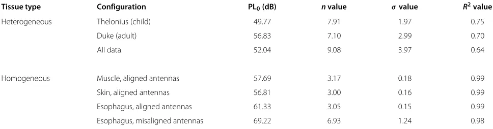
Table 2 Parameters for path loss models for homogeneous and heterogeneous tissues and phantoms (d0=250 mm)
Tissue type Configuration PL0(dB) nvalue σvalue R2value
Heterogeneous Thelonius (child) 49.77 7.91 1.97 0.75
Duke (adult) 56.83 7.10 2.99 0.70
All data 52.04 9.08 3.97 0.64
Homogeneous Muscle, aligned antennas 57.69 3.17 0.18 0.99
Skin, aligned antennas 56.81 3.00 0.16 0.99
Esophagus, aligned antennas 61.33 3.05 0.15 0.99
Esophagus, misaligned antennas 69.22 6.93 1.24 0.98
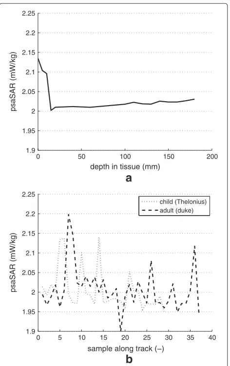
electromagnetic fields are defined in ICNIRP [22], namely, a maximum of 2 W/kg is allowed in 10 g of tissue (in the head and trunk). SAR (watt per kilogram) is defined as the rate at which energy is absorbed by the body when it is exposed to a radio frequency (RF) electromagnetic field. Compliance with the ICNIRP guidelines is inves-tigated for the 10 g localized SAR [22]. The maximum allowed radiated power in the MICS band is 25µW [23]. Figure 9a shows the peak spatial SAR (psaSAR) for the spiral when it is moved horizontally as a function of the depth inside the tissue. Also, the psaSARs for heteroge-neous tissues (adult and child) are shown (Figure 9b, see further). The highest values occur near tissue surface due to the proximity of the interface muscle-air. The values in Figure 9 are considerably lower than the ICNIRP basic restrictions (about 1,000 times lower than 2 W/kg) [22]. Moreover, as the worst case, one can determine the max-imum possible absorption, i.e., assuming that all power is absorbed in 10 g tissue with a maximum radiated power of 25µW. In that case, the psaSAR would be 2.5 mW/kg which is still below the ICNIRP basic restriction for localized absorption.
−10055 −50 0 50 100
56 57 58 59 60 61 62 63 64
dv (mm)
PL (dB)
muscle skin esophagus
Figure 7Path loss versus vertical displacementdvof the spiral.
Path loss for heterogeneous phantom models
Path loss models
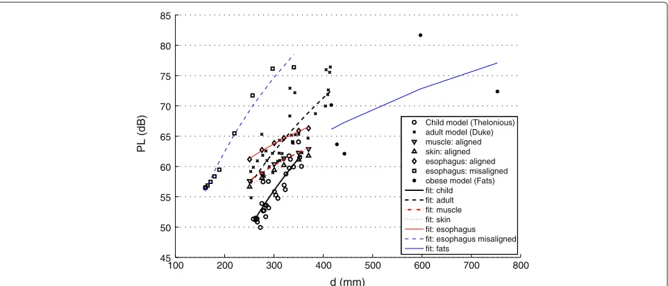
Figure 10 compares the simulated PL in two realistic human body models with the PL in homogeneous tis-sues for different separations. A comparison between PL results of the adult and obese adult man will be made fur-ther. Figure 10 shows that of course different PL values can occur at a certain transmitter Tx- receiver Rx separa-tion for different locasepara-tions throughout the digestive tract (crosses for adult and circles for child in Figure 10): The capsule travels in the heterogeneous models along a tract through the pharynx, the esophagus, the stomach lumen, and the small and large intestines’ lumen. Moreover, mis-alignments between Tx and Rx antennas occur. In gen-eral, the PL increases with the distance between antennas for heterogeneous tissues. The slope of simulated PL in the realistic human body models is clearly higher than for the PL in homogenous tissues due to the changes in the characteristic impedances of the different tissues and misalignment situations when traveling along the digestive tract.
−150 −100 −50 0 50 100 150
58 60 62 64 66 68 70 72
angle (degrees)
PL (dB)
rotation around y−axis rotation around x−axis
0 50 100 150 200
Figure 9Peak spatial average SAR (10 g) of the transmitting spiral antenna.(a)Homogeneous muscle versus depth.(b)
Heterogeneous tissues of the adult and child models along the samples of the digestive tract.
Figure 10 shows that the path loss values for Duke (adult) are higher than the path loss values for Thelonius (child). This is due to the position of the dipole antenna (see Section ‘Configurations’), since for the child Thelo-nius it is placed in front of the body and for the adult Duke it is positioned at one side with the arm between the two antennas. The tissues in the arm add additional losses. Also the distance between body and dipole is smaller for Thelonius (13.5 cm) than for Duke (18.5 cm). The path loss for misalignment in the homogeneous esophagus tis-sue can be considered as the worst case, as the PL values are higher than those for the adult man configuration.
Table 2 summarizes fornand PL0values obtained using linear regression fitting (Equation 2). The PL exponents for Thelonius and Duke are similar and about 7 to 8 in Table 2. In the heterogeneous tissues, the path loss expo-nent is higher than the one in homogeneous tissues (about
equal to 3) because of the influence of the surrounding tissues and the mixture of alignment and misalignment situations. The path loss is considerably higher when the antennas are misaligned (doubling of the path loss expo-nentnand shift of PL0,dBof 7 dB when misaligned for the esophagus). The regression models for the heterogeneous phantoms haveR2values (a coefficient of determination) of about 0.7, which is good. AnF-test concluded that the regression is significant, i.e.,n=0, at the 5% significance level (F = 78− 81,p < 10−9). Standard deviations of 2.0 and 3.0 dB for the child and adult model are obtained, respectively. Finally, Table 2 shows that larger standard deviations σ correspond with lower R2 values. These regression models can be used for link budget calculations for in-to-out body communications.
Link budgets
Because of the proximity of the human body, antennas cannot be separated from the wireless propagation loss. Therefore, using the method of [28], one can calculate the maximum allowable path loss for sensor modules oper-ating in the MICS band. With the maximum permitted level of−16 dBm EIRP (equivalent isotropically radiated power) or 25µW and a sensitivity level of−90 dBm for 152 kbps and−99 dBm for 51 kbps [29], a nominal max-imum path loss (PLmax) of 74 dB for 152 kbps and 83 dB for 51 kbps is obtained, respectively. When comparing these maximum allowable path losses with the path loss models obtained in Figure 10, one can conclude that up to 400-mm separation wireless communication for the heterogeneous phantoms (adult and child) is possible for both data rates for the considered configurations (for the adult configuration higher separations can be difficult). However, for misalignment in the esophagus tissue, sep-arations up to about 293 mm are possible for 152 kbps. The provided models of Table 2 can be used for further link budget calculations accounting for misalignment and rotation of the endoscopy capsule. To specifically account for the rotation, one can add a margin of 4 dB (x-axis) or 10 dB (y-axis) in the link budget. Also the application of the model with misaligned antennas is a possibility. A rotation of the capsule can result in a variation of the path loss up to 14 dB (10 and 4 dB margins).
Comparison of path loss for adult and obese adult men
100 200 300 400 500 600 700 800 45
50 55 60 65 70 75 80 85
d (mm)
PL (dB)
Child model (Thelonious) adult model (Duke) muscle: aligned skin: aligned esophagus: aligned esophagus: misaligned obese model (Fats) fit: child fit: adult fit: muscle fit: skin fit: esophagus fit: esophagus misaligned fit: fats
Figure 10Path loss for homogeneous and heterogeneous tissues in adult and child and corresponding regression models.Distance dipole-body of 18.5 cm for adult and obese model, Figure 2a; distance dipole-body of 13.5 cm for child model, Figure 2b.
endoscopy capsule in Fats can be horizontally aligned with the dipole outside the human body and, thus, no misalignment loss is present. But in the Duke, the cap-sule will be positioned somewhere else in the body; the endoscopy capsule and dipole outside the body will not be horizontally aligned and misalignment loss occurs, which can result in a larger PL than for the obese model. More-over, in the particular cases of Duke and Fats, when the dipole and the capsule are horizontally aligned, the prop-agation distance of the electromagnetic waves through the arm of Duke is about 2 cm longer, because near the wrists the arm of Fats is 2 cm smaller than the arm of Duke.
The mean and the maximum path loss in Fats equals to 70 and 82 dB, respectively. With respect to the adult this is 64 and 76 dB. This analysis shows that one has to be careful when making link budget evaluations: communi-cation is possible for Fats for the considered configuration of 51 kbps.
Human absorption
Figure 9b shows also the psaSAR for the adult and child human body models (heterogeneous tissues) along the samples of the digestive tract. There are of course more samples for the adult (Duke) than for the child (Thelo-nius) because of the larger dimensions of the adult and thus longer tract. The absorption values are averaged in 10-g mass for an input power of 25 µW. PsaSAR val-ues for both phantoms are similar and compliant with the ICNIRP guidelines is obtained (psaSAR 10 g val-ues are below 2 W/kg). The highest values are about 2.2 mW/kg for the maximum allowed transmission power of 25µW. Figure 9a,b has the same scale, enabling visual
comparison. The absorption values in heterogeneous tis-sues are comparable (slightly higher maximum) with the absorptions for the homogeneous muscle tissue. Peaks for the heterogeneous models occur due to the proximity of tissue boundaries.
Conclusions
Competing interests
The authors declare that they have no competing interests.
Authors’ information
WJ is a post-doctoral fellow of the FWO-V (Research Foundation - Flanders).
Acknowledgements
This research is partly funded by the Fund for Scientific Research - Flanders (FWO-V, Belgium) project G.0049.09N.
Received: 1 October 2013 Accepted: 6 January 2014 Published: 1 February 2014
References
1. J Ryckaert, P De Doncker, R Meys, A de Le Hoye, S Donnay, Channel model for wireless communication around human body. IEE Electron. Lett.40(9), 543–544 (2004)
2. L Roelens, S Van den Bulcke, W Joseph, G Vermeeren, L Martens, Path loss model for wireless narrowband communication above flat phantom. IEE Electron. Lett.42(1), 10–11 (2006)
3. A Alomainy, Y Hao, X Hu, CG Parini, PS Hall, UWB on-body radio propagation and system modelling for wireless body-centric networks. IEE Proc. Commun.153(1), 107–114 (2006)
4. A Fort, C Desset, P De Doncker, P Wambacq, L Van Biesen, An
ultra-wideband body area propagation channel model - from statistics to implementation. IEEE Trans. Microw. Theory Tech.54(4), 1820–1826 (2006) 5. L Roelens, W Joseph, E Reusens, G Vermeeren, L Martens, Characterization
of scattering parameters near a flat phantom for wireless body area networks. IEEE Trans. Electromagn. Compatibility.50(1), 185–193 (2008) 6. E Reusens, W Joseph, B Latre, B Braem, G Vermeeren, E Tanghe, L Martens,
C Blondia, I Moerman, Characterization of on-body communication channel and energy efficient topology design for wireless body area networks. IEEE Trans. Inf. Technol. Biomed.13(6), 933–945 (2009) 7. PS Hall, Y Hao, YI Nechayev, A Alomainy, CC Constantinou, C Parini, MR
Kamarudin, TZ Salim, DTM Hee, R Dubrovka, AS Owadally, W Song, A Serra, P Nepa, M Gallo, Antennas and propagation for on-body communication systems. IEEE Antenna Propagation Mag.49(3), 41–58 (2007)
8. A Alomainy, Y Hao, ACP Owadally, Y Nechayev, P Hall, CC Constantinou, Statistical analysis and performance evaluation for on-body radio propagation with microstrip patch antennas. IEEE Trans. Antennas Propagation.55(1), 245–248 (2007)
9. Y Zhao, Y Hao, A Alomainy, CG Parini, UWB on-body radio channel modelling using ray theory and sub-band FDTD method. IEEE Trans. Microw. Theory Tech. Spec. Issue Ultra-Wideband.54(4), 1827–1835 (2006) 10. SL Cotton, WG Scanlon, Statistical analysis of indoor multipath fading for
a narrowband wireless body are network, inIEEE 17th International Symposium on Personal, Indoor and Mobile Radio Communications(IEEE Piscataway, 2006), pp. 1–5
11. AF Molisch, K Balakrishnan, C Chong, S Emami, A Fort, J Karedal, J Kunisch, H Schantz, U Schuster, K Siwiak,IEEE 802.15.4a Channel Model - Final Report. Technical report, IEEE 802.154a Channel Modeling Subgroup (2004). Available at http://www.ieee802.org/15/pub/04/15-04-0662-02-004a-channel-model-final-report-r1.pdf. Accesses 28 January 2014 12. A Alomainy, Y Hao, Modeling and characterization of biotelemetric radio
channel from ingested implants considering organ contents. IEEE Trans. Antennas Propagation.57, 999–1005 (2009)
13. D Kurup, W Joseph, G Vermeeren, L Martens, Path loss model for in-body communication in homogenous human muscle tissue. IET Electron. Lett.
45(9), 453–454 (2009)
14. T Aoyagi, K Takizawa, T Kobayashi, J-i Takada, R Kohno, Development of a WBAN channel model for capsule endoscopy. Antennas Propagation Soc. Int. Symp, 1–4 (2009)
15. M Scarpello, D Kurup, H Rogier, D Vande Ginste, F Axisa, J Vanfleteren, W Joseph, L Martens, G Vermeeren. Accepted IEEE Trans. Antennas Propagation.59(10), 3556–3564 (2011)
16. A Kiourti, K Nikita, Miniature scalp-implantable antennas for telemetry in the MICS and ISM bands: design, safety considerations and link budget analysis. IEEE Trans. Antennas Propagation.60(8), 3568–3575 (2012) 17. S Agneessens, PV Torre, E Tanghe, G Vermeeren, W Joseph, H Rogier,
On-body wearable repeater as a data link relay for in-body wireless
implants. IEEE Antennas Wireless Propagation Lett. AWPL Spec. Issue Wireless Power Data Telemetry Med. Appl.11(12), 1714–1717 (2013) 18. D Kurup, W Joseph, G Vermeeren, L Martens, In-body path loss model
for homogeneous human tissues. IEEE Trans. Electromag. Compat.
54(3), 556–564 (2012)
19. A Alomainy, Y Hao, Y Yuan, Y Liu, Modelling and characterisation of radio propagation from wireless implants at different frequencies, in
Proceedings of the 9th European Conference on Wireless Technology
(Manchester, 10–12 September 2006), pp. 119–122
20. D Kurup, W Joseph, G Vermeeren, L Martens,Specific absorption rate and path loss in specific body location in heterogeneous human model, (2012). 10.1049/iet-map.2011.0559
21. SH Lee, J Lee, YJ Yoon, SPC Cheon, K Kim, S Nam, A wideband spiral antenna for ingestible capsule endoscope systems: experimental results in a human phantom and a pig. IEEE Trans. Biomed. Eng.
58(6), 1734–1741 (2011)
22. ICNIRP, Guidelines for limiting exposure to time-varying electric, magnetic, and electromagnetic fields. Health Phys.74, 494–522 (1998) 23. ETSI, ETSI EN 301 839-1 V1.3.1 (2009-10). Electromagnetic compatibility and radio spectrum matters (ERM); short range devices (SRD); ultra low power active medical implants (ULP-AMI) and peripherals (ULP-AMI-P) operating in the frequency range 402 MHz to 405 MHz; part 1: technical characteristics and test methods. (2009). http://www.etsi.org/deliver/ etsi_en/301800_301899/30183901/01.03.01_60/en_30183901v010301p. pdf. Accessed 28 January 2014
24. A Christ, W Kainz, E Hahn, K Honegger, M Zefferer, E Neufeld, W Rascher, R Janka, W Bautz, J Chen, B Kiefer, P Schmitt, H Hollenbach, J Shen, M Oberle, D Szczerba, A Kam, J Guag, N Kuster, The virtual family–development of surface-based anatomical models of two adults and two children for dosimetric simulation. Phys Med. Biol.55(2), 23–38 (2010)
25. S Gabriel, RW Lau, C Gabriel, The dielectric properties of biological tissues: measurements in the frequency range 10 Hz to 20 GHz. Phys. Med. Biol.
41(11), 2251–2269 (1996)
26. CA Balanis,Antenna Theory, Analysis and Design, 1st ed. (Harper & Row, New York, 1982), pp. 64–65
27. R Vaughan, JB Andersen,Channels, Propagation and Antennas for Mobile Communications. Electromagnetic Waves Series 50, The Institute of Electrical Engineers (IEE). (Michael Faraday House, Stevenage, UK, 2003)
28. E Tanghe, W Joseph, P Ruckebusch, L Martens, I Moerman, Intra-, inter-, and extra-container path loss for shipping container monitoring systems. IEEE Antennas Wireless Propagation Lett.11, 130–132 (2012)
29. IEEE P802.15 Working Group for Wireless Personal Area Networks (WPANs). doc IEEE 802.15-10-0802-00-0006. http://www.ieee802.org/15/. Accessed 28 January 2014
doi:10.1186/1687-1499-2014-21
Cite this article as:Lopez-Linares Romanet al.:Characterization of path loss and absorption for a wireless radio frequency link between an in-body endoscopy capsule and a receiver outside the body.EURASIP Journal on Wireless Communications and Networking20142014:21.
Submit your manuscript to a
journal and benefi t from:
7Convenient online submission 7Rigorous peer review
7Immediate publication on acceptance 7Open access: articles freely available online 7High visibility within the fi eld
7Retaining the copyright to your article
![Figure 4 Capsule with spiral antenna and dielectric containerstuned to 402 MHz [21].](https://thumb-us.123doks.com/thumbv2/123dok_us/961353.1117849/4.595.296.539.85.350/figure-capsule-spiral-antenna-dielectric-containerstuned-mhz.webp)