Abstract— The narrow bandwidth of microstrip antenna is one of the important features that restrict its wide usage. This paper presents a bandwidth enhancement using array technique and combined with transformator λ/4 for the feed line matching is proposed and experimentally studied. The maximum bandwidth can be achieved by controlling the distance between the two patch antennas and by adjusting the length of the transmission feed line 50 Ohm. Return loss of -15.45 dB with VSWR 1.406 for the first frequency at 2.3 GHz and return loss of -32.77 dB with VSWR 1.047 for the second frequency at 3.3 GHz. The results show that the proposed antenna has the impedance bandwidth of 14.6% for the first frequency and 41.87% for the second frequency. Gain of 8.98 dB and radiation pattern with HPBW 200can be obtained.
Index Term-- Array, triangular microstrip antenna, bandwidth, transformator λ/4, WiMAX
I. INTRODUCTION
Patch antenna possesses many advantages such as low profile, light weight, small volume and compability with microwave integrated circuit (MIC) and monolithic microwave integrated circuit ( MMIC ). However, the narrow bandwidth is the major obstacle in wide applications for the microstrip antenna. In general, the impedance bandwidth of the traditional microstrip antenna is only a few percent (2% - 5%) [1]. Therefore, it becomes very important to develop broadband technique to increase the bandwidth of the microstrip antenna.
There are several ways to overcome this problem such as use U-slotted patch [2] and use array technique [3], but [2] and [3] still use rectangular patch microstrip antenna. Although rectangular and circular geometries are most commonly used, other geometries having greater size reduction find wide applications in
modern communication systems, where the prime concern is compactness. The triangular patch antenna configuration is chosen because it has the advantage of occupying less metalized area on substrate than other existing configurations.
In some applications which the increased bandwidth is needed, dual frequency patch antenna is one of the alternative
solutions [4]. When modern communication system, such as satellite, radar and wimax requires operation at two frequencies, dual frequency patch antennas may avoid the use of two different antennas. Basically, dual frequency patch antenna will be divided as orthogonal mode dual frequency patch antenna, multi patch dual frequency antenna, and reactively loaded dual frequency patch antenna [4]. Recently, the most popular technique for obtaining dual frequency is by introducing a reactive loading to a single patch [5][6][7].
Mainly there are two feeding systems and can be categorized into two groups, direct coupling or probe feed and electromagnetic coupling. Microstrip line and coplanar waveguide are two types of transmission line and usually used as a feeding line for the electromagnetic coupling. The advantage of electromagnetic coupling is permits for improving bandwidth [8].
Using geometry and dimension from [7] this paper therefore proposed a design of triangular microstrip antenna array using transformator λ/4 for the feed line matching technique and add between the two transmission feed line 100 Ohm from the two patch antennas. Details of the proposed antenna design and the results of the dual frequency to enlarge the bandwidth performances are presented.
II. ANTENNA DESIGN
The geometry of a single patch antenna using two slots with different height for dual frequency operation feed by microstrip feed line can be shown in Figure 1a and 1b. The patch antenna is constructed on two layers with the same dielectric substrate. On the first layer, the patch antenna is realized on FR 4 substrate and having a relative permittivity (r) = 4.98, substrate of thickness (h) = 1.53 mm and loss
tangent (tan) = 0.09 and the microstrip feed line is realized on the second layer.
Figure 1a, ais the dimension of the side length of the triangular patch antenna and given by ∶
𝑎 =
2𝑐3𝑓√𝜀𝑟
(1)
Increasing Bandwidth Dual Frequency
Triangular Microstrip Antenna
For WiMAX Application
Indra Surjati, Yuli KN and Yuliastuti
Department of Electrical Engineering Faculty of Industrial Technology Trisakti University Jl. Kyai Tapa No.1 Grogol, Jakarta 11440, Indonesia
a1 is the left length of the triangular and the first slot, a2 is distance between the first slot and the second slot, a3 is the right length of the triangular and the second slot. Beside that, x1 and y1 are the length and width of the first slot, x2 and y2 are the length and the width of the second slot. Table Ia shown the parameters of a single satch antenna.
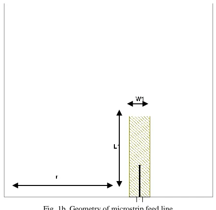
Figure 1b, W1 and L1 are the length and width of the feeding system and r is the distance from the left side of the triangular patch antenna to microstrip feed line. Table Ib shown the parameters of microstrip feed line.
Table Ia
Parameters of a single patch antenna
Parameter a a1 a2 a3 x1 x2 y1 y2 Length (mm) 24 9 5 8 10 8 1 1
Table Ib
Parameters of microstrip feed line
Parameter W1 L1 r
Length (mm) 2.8 12,5 18
Fig. 1a. Geometry of a single patch antenna
Fig. 1b. Geometry of microstrip feed line
For array technique, the minimum distance between the two patch antennas can be calculated as follow:
d = λ/2 (2)
Transformator λ/4 is an impedance matching technique by providing transmission feed line with a matching impedance ZT between the two transmission feed line that does not match each other as seen in Figure 2 and given by :
ZT = Z1Z3 (3)
Z
1Z
3Z
Tλ
g/4
Fig. 2. Transformator λ/4
From (3) the impedance of transformer λ/4 is 70.7 Ohm and the length of transformer λ/4 transmission feed line is given by:
l
g4
1
(4)and can be seen in Figure 3. While
λ
gis the wavelength of the dielectric substrate and can be calculated as follow:
eff
g
01
¼λ ¼λ
Fig. 3. Length of the transformator λ/4
To calculate the width of the microstrip feed line 100 Ohm, 70.7 Ohm and 50 Ohm is given by :
𝐵 =
60𝜋2𝑍0√𝜀𝑟
(6)
𝑊 = 2ℎ
𝜋 {𝐵 − 1 − ln(2𝐵 − 1) +
𝜀𝑟−1
2𝜀𝑟 [ln(𝐵 − 1) + 0,39 −
0,61 𝜀𝑟]} (7)
From (6) and (7), the width of the three transmission feed line for the proposed antenna are as follow 0.5 mm, 1.5 mm and 3 mm respectively for 100 Ohm, 70.7 Ohm and 50 Ohm.
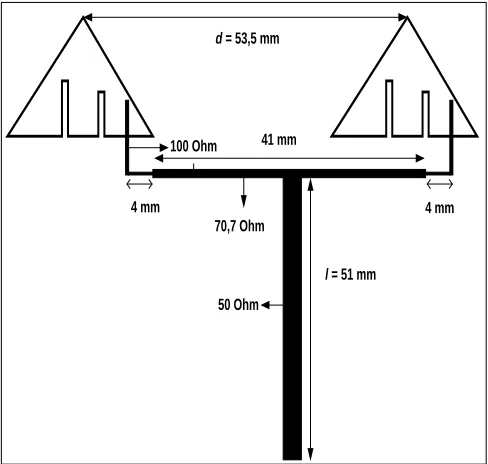
Figure 3 shows the geometry and the dimension of the proposed antenna.
l = 51 mm
4 mm 4 mm
d = 53,5 mm
100 Ohm
70,7 Ohm
50 Ohm 41 mm
Fig. 3. Geometry and dimension of the proposed antenna
III. EXPERIMENTAL RESULTS
The results of the first condition of the proposed antenna is as follow, return loss of -10.82 dB with VSWR 1.808 at frequency 2.3 GHz and return loss of -15.16 dB with VSWR 1.423 at frequency 3.3. GHz. The results shows that return loss and VSWR did not indicate the maximum value. To achieve the maximum results, the distance between the two patch adjusted and the length of the microstrip feed line 50 Ohm need to be controlled.
Table II shows the comperation results after controlling the length of the microstrip feed line 50 Ohm and Figure 4 shows the return loss value.
Table II
Iteration of the length of the microstrip feed line 50 Ohm Length of the
microstrip feed line 50 Ohm
Frequency 2.3 GHz Frequency 3.3 GHz
Return Loss
VSWR Return Loss
VSWR
42 mm -11.50 dB 1.725 -12.77 dB 1.600 46 mm -13.05 dB 1.573 -12.78 dB 1.599 51 mm -17.58 dB 1.304 -17.25 dB 1.298
Fig. 4a. Return loss after adjusting the length of the microstrip feed line
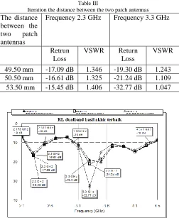
Figure 4a shows that frequency 3.3 GHz is not in the right position. By adjusting the distance between the two patch antennas the frequency can be shifted to the right position as seen in Table III and Figure 5.
Table III
Iteration the distance between the two patch antennas The distance
between the two patch antennas
Frequency 2.3 GHz Frequency 3.3 GHz
Retrun Loss
VSWR Return Loss
VSWR
49.50 mm -17.09 dB 1.346 -19.30 dB 1.243 50.50 mm -16.61 dB 1.325 -21.24 dB 1.109 53.50 mm -15.45 dB 1.406 -32.77 dB 1.047
Fig. 5a. Return loss after adjusting the distance between the two patch antennas
Fig. 5b. VSWR after adjusting the distance between the two patch antennas
After controlling the distance between the two patch antenna and microstrip feed line 50 Ohm, Table 4 shows the comperation between the single patch antenna and the antenna array.
Table IV
The comperation between a single patch antenna and the antenna array
Parameter Single element Array 2 element
Center Frequency
2.3 GHz 3.3 GHz 2.3 GHz 3.3 GHz
Return Loss -22.65dB -20.37dB -15.45 dB -32.77 dB VSWR 1.159 1.212 1.406 1.047 Bandwidth 273 MHz 294 MHz 338 MHz 1382 MHz
Table IV shows that for the first frequency at 2.3 GHz has the impedance bandwidth 273 MHz or about 11.86% and for the second frequency at 3.3 GHz is 294 MHz or about 8.9%.
Figure 5a and Table IV shown that impedance bandwidth for frequency at 2.3 GHz is 338 MHz or about 14.6% and for the second frequency at 3.3 GHz is 1382 MHz or about 41.87%. It is seen that the proposed antenna can increase the bandwidth.
Gain of the proposed antenna can be calculated as follow :
𝜀
𝑒𝑓𝑓=
𝜀𝑟+1
2
+
𝜀𝑟−1
2
[
1
√1+12ℎ 𝑊⁄
]
= 4,51986𝛽 =
2𝜋√𝜀𝜆 𝑒𝑓𝑓0
= 148,347 𝑟𝑎𝑑 = 8500,283 °
𝐷𝑎𝑟𝑟𝑎𝑦 = [
1 N+
2 N2 ∑
N − m
mβd sin mβd cos mα
N=−1
m=1
]
−1
= 2
If directivity element for W << λ0 is 6.6, than
𝐷𝑡𝑜𝑡𝑎𝑙 = 𝐷𝑎𝑟𝑟𝑎𝑦× 𝐷𝑒𝑙𝑒𝑚𝑒𝑛= 2 × 6,6= 13.2
Efficiency (𝜼) for microstrip antenna 60%, gain of the proposed antenna can be calculated as follow : 𝐺 = 𝜂. 𝐷= 8.98 dB.
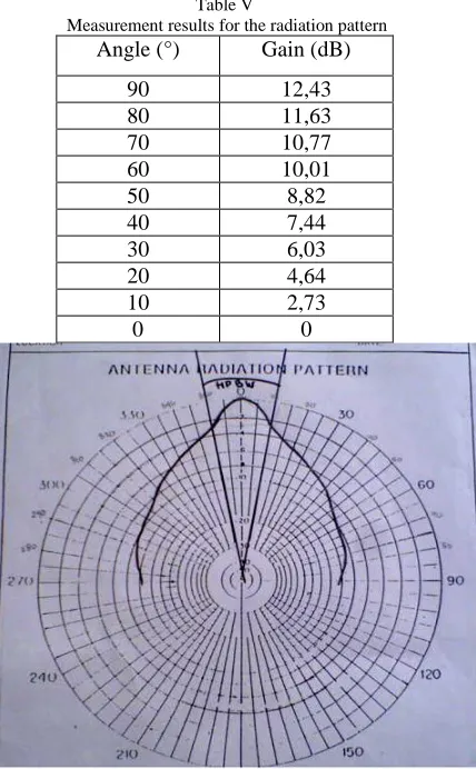
Figure 6 Radiation pattern of the proposed antenna Furthermore, the measurement for the radiation pattern of the proposed antenna is done only at the frequency 2.3 GHz as seen in Table V and Figure 7 shown the radiation pattern with Half Power Beam Width (HPBW) 200.
Table V
Measurement results for the radiation pattern Angle (°) Gain (dB)
90 12,43
80 11,63
70 10,77
60 10,01
50 8,82
40 7,44
30 6,03
20 4,64
10 2,73
0 0
Fig. 7. Radiation pattern with HPBW 200
IV. CONCLUSION
A novel configuration to increase bandwidth dual frequency microstrip antenna array for WiMAX application has been experimentally studied.It is shown that the two frequencies can be easily controlled by varying the length of the microstrip feed
line 50 Ohm and adjusting the distance between the two patch antennas. It is observed that return loss of -15.45 dB with VSWR 1.406 can be achieved for the first frequency at 2.3 GHz and the impedance bandwidth is about 14.60%. For the second frequency at 3.3 GHz, return loss of -32.77 dB with VSWR 1.047 has the impedance bandwidth of 41.87%. In addition, the gain of the proposed antenna is 8.98 dB and have radiation pattern with HPBW 200. Therefore the proposed antenna is applicable as a new candidate for dual frequency antenna to enlarge the bandwidth for WiMAX application.
REFERENCES
[1] Pozar, D.M, “Microstrip Antennas”, Proceeding of The IEEE, Vol.40, No.1, January 1992
[2] Chai, Wenwen et al, “Wideband Microstrip Antenna using U Slot”, PIERS Online, Vol.3, No.7, 2007
[3] Mallikarjun, S.L et al, “Development of Microstrip Array Antenna For Wide Band and Multi Band Application”, Indian Journalof Radio and Space Physics, Vol.38, October 2009
[4] Maci, S and G.B.Gentili, “Dual Frequency Patch Antennas”, IEEE Antennas and Propagation Magazine, Vol.39, No.6, December 1997
[5] Surjati, Indra, “Dual Frequency Operation Triangular Microstrip Antenna Using A Pair Of Slit”, 11th Asia Pacific Conference on Communications, Perth, Western Australia, October 2005
[6] Anguera, J, et al, “Dual Frequency Broadband Microstrip Antenna With A Reactive Loading And Stacked Elements”, Progress In Electromagnetics Research Letters, Vol.10, 1 – 10, 2009
[7] Surjati, I et al, “Dual Band Triangular Microstrip Antenna Using Slot Feed By Electromagnetic Coupling”, Proceeding Quality in Research, Faculty of Engineering, University of Indonesia, 2009
[8] Rahardjo, E.T, “Studies On The Microstrip Antennas Fed By Electromagnetic Coupling”, Doctoral Thesis, Saitama University, March 1996
0
-10
-20 -30
-40
-50
-60
-70
-80
-90
-100
-110 -120
-130
-140
-150
-160 -170 180 170 160
150
140 130
120 110
100
90
80
70 60 50
40
30
20 10
pola radiasi
Mag Max 7 dB
Mag Min 2 dB 1 dB
Per Div
Mag 3.15 dB Ang 60.43 dB Mag 3.149 dB
Ang -46.78 dB Mag 6.149 dB Ang 0.251 dB