R E S E A R C H
Open Access
4-ary network coding for two nodes in
cooperative wireless networks: exact outage
probability and coverage expansion
Jin-Taek Seong and Heung-No Lee
*Abstract
The fact that sensor nodes are powered by limited-capacity batteries makes power efficiency; one of the most critical issues in wireless sensor networks (WSNs). Advanced communication techniques combined with network coding and cooperative schemes have attracted considerable attention as ways to improve power efficiency in wireless transmission as well as to achieve high throughput and spectral efficiency in WSNs. In this study, we consider cooperative wireless networks with two nodes and one base station, and investigate the effect of using non-binary network coding on the enhancement in power efficiency. First, we derive the exact and general outage probability in our network coding scheme. We show that full diversity order can be obtained using a non-binary network code with GF(4) in the considered network. We use this result to study the extent to which the coverage area of a wireless source node can be expanded by network coding without increasing transmit power. Our results indicate that the benefit in terms of coverage expansion is substantial. The results included in this study show the influence of optimal power allocation on power efficiency. The optimum ratio of power allocation varies according to the wireless channel environments and the field size of network codes.
Keywords:Wireless sensor network, Outage probability, Non-binary network coding, Cooperative network, Power efficiency, Coverage expansion, Power allocation
1. Introduction
In wireless sensor networks (WSNs), sensor nodes oper-ate on the limited energy source of onboard batteries, making power efficiency a key issue because replacement or recharging of batteries is difficult. The very high-energy expenditure of WSNs makes long-range message transmission undesirable. Consuently, there are several ways to improve power efficiency, such as optimal trans-mit power allocation [1-5].
Channel fading is one of the underlying causes of per-formance degradation in wireless networks. One naïve approach to combating fading is to increase the transmit power. A more advanced method is to use diversity techniques, which can be employed without increasing the transmit power. To date, many diversity techniques have been developed and employed in time, frequency, and space domains. Cooperative networking is a modern
approach that aims at increasing spatial diversity via user cooperation. Each user participates in collaboration and shares the benefit of using a virtual antenna array in transmitting information to a receiver that is available through another user’s antenna [6]. Ahlswede et al. [7]
proved thatnetwork coding achieves optimality in terms
of the flow rate for a single-source multicast scenario. This would be impossible to achieve by simply routing or by replicating the data. Many studies have since been conducted to verify that network coding provides advan-tages over existing cooperative network schemes [8-13].
Analyses of outage probability in cooperative networks are presented in [6,14-19]. Chen et al. [15] showed that binary network coding (BNC), based on the arithmetic of a Galois Field of size 2, i.e., GF(2), provides improved diversity gains and bandwidth efficiencies in wireless networks in which each user employs a simple decode-and-forward (DF) scheme that assumes a perfect inter-user channel. In practice, there exist channel errors be-tween users, as discussed in [16], where the authors
* Correspondence:[email protected]
School of Information and Communications, Gwangju Institute of Science and Technology (GIST), Gwangju, South Korea
proposed an adaptive DF scheme with BNC. It was re-cently shown in [17] that BNC is not optimal for achiev-ing full diversity in a system of multiple users and relays. However, it has also been shown that full diversity order can be achieved using non-binary network coding (NBNC) with GF(q) forq >2 [17-19].
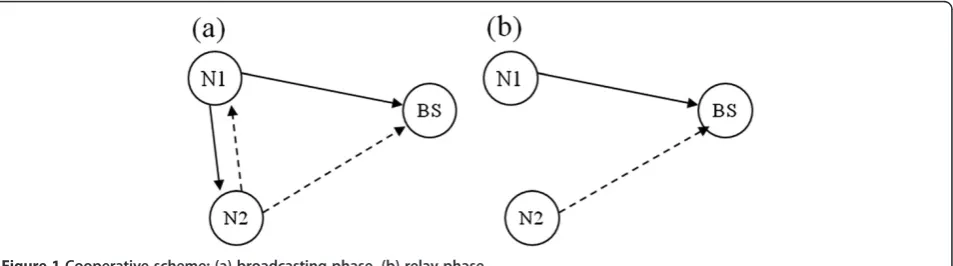
In this study, we consider a cooperative wireless network, where there are two source nodes and one base station (BS) as depicted in Figure 1. We investigate the effect of using network coding and optimal transmit power allocation on power efficiency. Power efficiency is expressed as (i) the outage probabilities from sources to destinations and (ii) expansion of the network coverage area. We also derive a general and exact outage analysis framework using which we can investigate the influence of field sizes in network coding, transmit powers, trans-mission rates, and network topologies on the outage performance of the network. Specifically, we show that using NBNC yields full diversity order as well as expan-sion of the network coverage area. We show that a mere increase in the size of the finite field in network coding, i.e., without incurring additional cost such as boosting the transmit power level, can lead to a substantial gain in the network coverage area. To the best of the authors’ knowledge, there have been no reports that associate an increased field size in network coding to the expansion of network coverage area. In addition, an analysis of the optimal power allocation (OPA) for both cooperative schemes is useful for determining the power efficiency of various network environments, i.e., according to the positions of source nodes. Another interesting result obtained in this study is that the OPA depends on the size of finite fields.
The remainder of this article is organized as follows. In Section 2, we describe cooperative schemes, channel model, and outage probability. In Section 3, the exact outage probability in cooperative networks is derived and analyzed for different network coding schemes. Power efficiency techniques based on outage probabilities are described in Section 4. Finally, we conclude this study in Section 5.
2. System description 2.1. Cooperative schemes
Cooperative transmission schemes can be divided into two categories based on the method employed to process messages at intermediate nodes: the amplify-and-forward (AF) scheme and the DF scheme, both are widely used relay protocols [6]. In the AF scheme, an intermediate
node receives a noisy signal of the source’s message,
amplifies it in non-regenerative mode, and forwards it to a destination. In the DF scheme, a relay node decodes the source’s message, re-encodes it, and forwards it to the destination. We focus on the second of these cooperative transmission protocols, i.e., the DF scheme.
We consider a cooperative scheme for wireless net-works as shown in Figure 1. There are two source nodes, nodes 1 (N1) and 2 (N2), and two phases, the broadcast-ing and the relay phases, in the cooperative scheme. In the broadcasting phase, source nodes N1 and N2 trans-mit messages,S1and S2, respectively. In the relay phase,
when both nodes successfully recover the transmitted messages, the messages are re-encoded and then for-warded to the BS. When a node is unable to successfully perform decoding, it repeats its message in the relay phase. When receiving repeated messages, BS as a des-tination performs maximum ratio combining (MRC) of these messages, and recovers the transmitted messages. In this study, we assume that the transmission rate is selected to be sufficiently lower than the capacity of each channel so that near perfect decoding of messages can be accomplished with the use of a channel code. Thus, for all wireless channels, the received messages are either completely corrupted, and therefore not available at the receiving end, or considered error-free.
At the BS, the set of all possible received messages is {S1,S2,Z1,Z2}, where the subscript denotes the index of
the source node. The first two messages are received in the first phase, and the latter two are linearly combined and sent from the sources in the relay phase. The alpha-bet of the combined message, Z1 and Z2, is selected to
be a finite field. The two finite fields considered in this study are GF(2) and GF(4).
Suppose that the relay nodes use a binary field for the network coding operation, a method we refer to as BNC in this article. Then, the received messages at BS in the two phases are represented as
S1
whereH2is the network coding matrix with its elements
drawn from GF(2) and S is the source message vector.
The arithmetic should follow that of GF(2). Most exist-ing network codexist-ing schemes are based on BNC.
For the case of NBNC with GF(4), referred to as NBNC-4 in this article, the messages received at BS are rewritten as
where H4 is the network coding matrix composed of
elements from GF(4) and the arithmetic operations are those of GF(4).
The core idea of cooperative communication systems is to alleviate the negative effects of communication channels, such as fading and noise, and to increase the probability of successful message reception via cooper-ation. With a closer look at the rows ofH4, we note that
any two rows ofH4are linearly independent, while those
of H2 may not be. This means that as long as any two
messages out of the four, {S1,S2,Z1,Z2}, are received
correctly, NBNC-4 can correctly decode the correct transmit messages S1 and S2. This is not possible with
the BNC scheme. For example, the last two rows ofH2
are dependent on each other. Thus, with the reception
of only Z1and Z2, the BNC scheme cannot decode the
messagesS1andS2accurately. For a network of two-user
cooperation, this desirable behavior can be attained by increasing the field size to 4. This behavior was first observed in [17]. In this article, our focus again is to show how this favorable behavior can lead to power efficiency in terms of coverage expansion, and to study how the transmit power should be allocated differently between the two sensors given a fixed power budget.
2.2. Channel model
Our system consists of a multiple access channel net-work in which there are two source nodes and one BS. In the broadcasting and relay phases, all source nodes transmit signals through orthogonal channels using time division multiple access or frequency division multiple access. The channels used in this study are assumed to be spatially independent, flat faded, and perturbed by additive white Gaussian noise (AWGN). We further assume that the channel gains in both the broadcasting and relay phases are mutually independent. The received signal at thejth node is thus
yi;j;k¼
ffiffiffiffi Pi
p
hi;jkxi;j;kþni;j;k; ð3Þ
where k∈{1, 2} denotes the transmission phase
(broad-casting or relay phase), andi,i∈{1, 2}, denotes the
trans-mitted node (N1 or N2). Letj denote the received node
forj∈{1, 2,d}, whereddenotes BS. The transmitted and received signals are given as xi,j,k and yi,j,k with i≠j. Pi
denotes the transmit power at theith node. The channel
gain is represented by hi,j,k, which consists of the fading
term pi,j,k and the path loss coefficient qi,j,k, i.e., hi,j,k=
pi,j,kqi,j,k. Here, we assume that the fading term pi.j,k is
random and the path loss coefficient qi,j,k depends on
the distance between nodesiandj. Noiseni,j,kis AWGN
with a normal distribution Nð0;N0Þhaving a zero mean and power spectral density N0. The path loss coefficient
is modeled as qi,j,k= (d0/di,j)α/2, where 2 <α< 6 is the
path loss exponent, di,j is the distance between nodes i
and j, andd0is the reference distance. In this study, we
used0= 1 andα= 3, and |hi,j,k| is assumed to be Rayleigh
distributed such that the channel energy of power |hi,j,k|2
is exponentially distributed. We assume that the fading term pi,j,k is a complex-valued, independent and
identi-cally distributed Gaussian in each dimension with a zero
mean and 1/2 variance. The average power of hi,j,k is
then represented by the average power of qi,j,k, which
depends on the distance between the transmitter and the receiver. All channel gains are assumed to be recip-rocal, i.e., hi,j,k=hj,i,k. The instantaneous signal-to-noise
ratio (SNR) of each channel is denoted asγi,j,k:= |hi,j,k|2Pi/
N0, wherePi/N0is the transmit SNR at the source nodei.
2.3. Outage probability
The channel capacity as a function of the received SNR at nodejis given by
Ci;j;k¼ log2 1þγi;j;k
; ð4Þ
whereCi,j,kdenotes the channel capacity from nodesito
single channel capacity Ci;j;k¼21log 1þγi;j;k
for each
transmission phase because a factor of 2 represents the bandwidth expansion for each node in the cooperative scheme. Channel outage occurs if the capacity is less
than the transmission rate R, where R is the desired
spectral efficiency in bits/s/Hz. For the Rayleigh fading channel, the outage probability is given and approxi-mated at a high SNR in the following manner:
Pout γi;j;k;R
average SNR and the transmission rate.
We assume that MRC is used at BS for combining identical transmissions. For the case of MRC, the prob-ability of an outage event is a function of two exponen-tially distributed random variables, which denote the instantaneous SNR for each channel. Thus, the outage probability for MRC at BS is represented as Pr{γs,d,k+
γr,d,k< 22R−1}, for s,r∈{1, 2}. The outage probability
with two random variables is obtained from the following
cumulative distribution function (CDF). Let w:=u+v,
whereuand vare independent exponential random
vari-ables with parametersλuandλu. The CDF of the random
variablewis given by
Pwð Þ ¼w 1
3. Outage probability for 4-ary network coding In this section, we aim to derive the outage probability that allows us to investigate the effects of different out-age events, transmit power allocations, channel gains, and field sizes (GF(2) versus GF(4)) in network coding, on power efficiency. This analysis is somewhat differ-ent from that given in a recdiffer-ent article [17] that studied outage probabilities under a number of approxima-tions: (i) they did not consider all possible outage sce-narios (for a full consideration see [14]), (ii) all channel
outages are treated with the same transmit powers, the same average channel gains, and thus the same average channel SNRs. Our analysis is exact and generalized, with consideration of different transmit powers, rates, and average channel gains. This generalized analysis framework enables us to conduct not only a diversity order analysis, but also a complete outage probability analysis as a function of SNR. These results help us investigate the coverage area expansion and the OPA problems. Our outage probability analysis shows that the diversity order achievable with NBNC-4 is three, instead of two, as obtained in [15]. It should be noted that full diversity order is obtainable in the considered network channel.
3.1. Outage events in the cooperative network
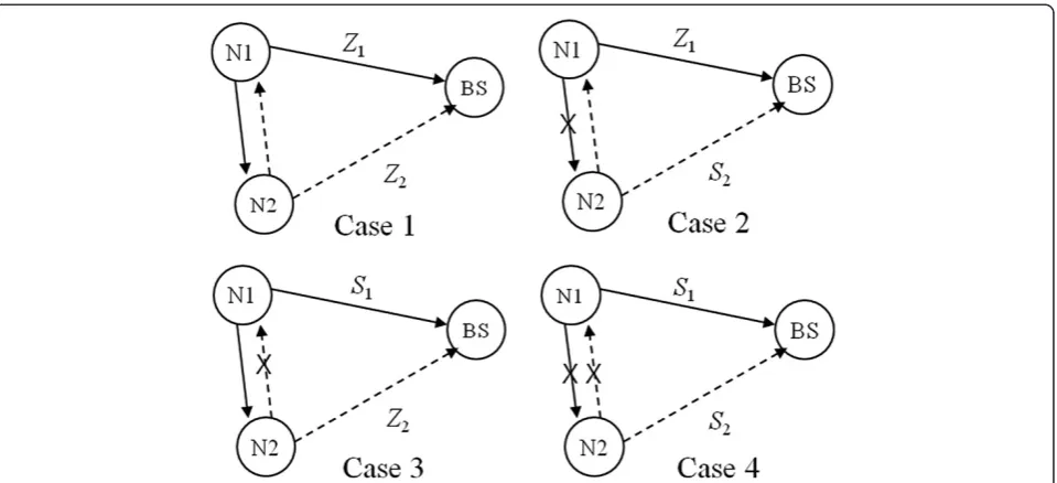
In the broadcasting phase, both source nodes transmit their messages to BS in an orthogonally multiplexed manner, and they overhear each other’s message. In the relay phase, the two source nodes act independently with no knowledge of whether their own broadcasted mes-sage was successfully decoded by their neighbor node. No feedback channel is assumed between the two nodes. As such, there are four possible cooperation scenarios depending on whether the decoding of messages was successful in the broadcasting phase. These four outage events are depicted in Figure 2, and the four cooperative scenarios for each of the four outage events are denoted as Cases 1, 2, 3, and 4.
In Case 1, both nodes successfully decode the partner’s message. In the relay phase, each node linearly combines
the neighbor’s message with a network coding, and
forwards the encoded message to BS, resulting in a fully cooperative scenario. In Case 2, N1 successfully decodes the message from N2, but N2 does not successfully
decode the message from N1. Hence, N1 combines N2’s
3.2. Outage probability for 4-ary network coding
In the following, we focus on the derivation of outage probability for the NBNC-4 scheme. First, network cod-ing in the relay phase is performed. Message transmis-sion consists of two phases as described in the previous section. We analyze the outage event based on MRC. In this study, we assume that the instantaneous SNRs for the broadcasting and relay phases are mutually independent.
Case 1: In this case, both nodes correctly decode each other’s messages. Correct decoding events are defined as follows.
C1;2;1>R1
\ C2;1;1 >R2
ð7Þ
We define the transmission rate for each node asR1and
R2, respectively. We consider the outage probability for
NBNC-4 in the relay phase follows the network coding method specified in (2).
Next, we consider the outage events for Case 1. Suppose that transmitted messages in the broadcasting phase from N1 and N2 are not decoded successfully at BS. This amounts to an outage event except when both of the com-bined messages with ratesR1andR2, respectively, are
suc-cessfully decoded in the relay phase. In this case, the outage probability can be written as
Pr C1;d;1<R1
\ C2;d;1<R2
\ C1;d;2<R1
\ C2;d;2<R2
¼Pr γ1;d;1<r1
n o
Pr γ2;d;1<r2
n o
ð1Pr γ1;d;2>r1
n o
Pr γ2;d;2>r2
n o
Þ;
ð8Þ
where r1¼22R11 and r2¼22R21. In addition,
con-sider the case in which the transmitted message in the broadcasting phase from N1 is not decoded successfully, but the transmitted message in the broadcasting phase from N2 is decoded successfully. An outage occurs only when decoding of both messages in the relay phase fails. This outage probability can be written as
Pr C1;d;1<R1
\ C2;d;1>R2
\ C1;d;2<R1
\ C2;d;2<R2
¼Pr γ1;d;1<r1
n o
Pr γ2;d;1>r2
n o
Pr γ1;d;2<r1
n o
Pr γ2;d;2<r2
n o
: ð9Þ Table 1 Transmitting messages for two nodes according
to the four scenarios
Case N1 N2
Broadcasting Relay Broadcasting Relay
1 S1 Z1 S2 Z2
2 S1 Z1 S2 S2
3 S1 S1 S2 Z2
4 S1 S1 S2 S2
As a result, the outage probability of N1 for Case 1
Case 2: In this case, N1 correctly decodes message S2
from N2, but N2 does not correctly decode message S1
from N1. This corresponds to the following events
C1;2;1<R1
\ C2;1;1 >R2
:
ð11Þ
According to the transmission protocol, BS receives N2’s messageS2twice, and decoding is performed using
MRC. Hence, the outage probability of N2 for MRC is obtained as
The outage probability in the conditional case is
Pr
where the first term of the RHS of (13) is the outage probability for N1, and the second term is for N2 that uses MRC. The overall outage probability for Case 2 is
P2out;4ary¼Pr γ1;2;1<r1
Case 3: In this case, N2 correctly decodes N1’s mes-sageS1, but N1 cannot decode node 2’s messageS2. The
Using the same approach as for Case 2, we obtain the overall outage probability as follows
Pout3 ;4ary¼Pr γ1;2;1>r1 The outage probability for N1 that uses MRC is
Pr MRCf 1g ¼Pr γ1;d;1þγ1;d;2<22R11
Case 4: Neither node decodes the message in the broadcasting phase successfully. The overall outage probability for Case 4 is
P4out;4ary¼Pr γ1;2;1<r1
n o
Pr γ2;1;1<r2
n o
Pr MRC1f g: ð18Þ
Next, the exact outage probability with NBNC-4 for N1 is obtained by adding the results so far, i.e., (10), (14), (16), and (18), as follows
Pout;4ary¼Pout1 ;4aryþPout2 ;4aryþPout3 ;4ary
þP4out;4ary: ð19Þ
Using the high SNR approximation given in the last line of (5), we can approximate the outage probability as follows
Pout;4ary≈
The outage probability analysis for BNC is performed similar to the analysis performed for the NBNC-4 scheme, with the result that the outage probabilities for BNC are identical to those for NBNC-4, except for the first case, i.e., Pout2 ,binary=Pout2 ,4−ary,Pout3 ,binary=Pout3 ,4−ary,
and Pout4 ,binary=Pout4 ,4−ary.. The reason for this is that the
outage events, in each of Cases 2, 3, and 4, for the BNC scheme, are identical to those of NBNC-4. The only differ-ence comes from Case 1.
The outage probability of BNC for Case 1 is given by
The exact outage probability for BNC using (1) is again obtained by summing the results
Pout;binary¼P1out;binaryþP2out;binaryþPout3 ;binary
þP4out;binary: ð22Þ The high SNR approximation is then given by
Pout;binary≈
B1 P1P2þ
B2 P2
1P2
þ B3
P1P2 2
þB4
P3 1
; ð23Þ
where B1:¼ r1r2N
2 0
σ2 1;dσ22;d;
B2:¼ r
2 1r2
2σ2 1;2σ21;dσ22;dþ
r2 1r2
2σ2 1;2σ22;1σ21;d;
B3:¼ r1r
2 2N
3 0
σ2 2;1σ21;dσ22;d;
andB4:¼ r12r2N03 σ2
1;2σ41;d:
3.3. Outage probability comparison of different transmission schemes
In this section, we evaluate the outage probability of N1 for both BNC and NBNC-4 in terms of the average
SNRs and the transmission rates R1 and R2. We show
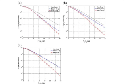
that using NBNC-4 provides improved outage probabilities compared to BNC for different channel environments. In Figure 3, we show evaluation results for which the benefits of network coding can be obtained at mid to high SNR
regions. We compare the outage probabilities for different network schemes, i.e., a non-cooperative scheme, a co-operative communication scheme with the binary network code, and a cooperative communication scheme with the 4-ary network code. These are labeled as Non-Coop, Binary Coop, and 4-ary Coop, respectively.
In order to investigate the influence of different channel gains, we assume that the transmit powers of the two nodes are equal, i.e., P1=P2, and we use the
same transmission ratesR1= R2=1 b/s/Hz. As shown in
Figure 3, we evaluate the effect of variances of the channel gains. We can observe that the NBNC-4 scheme achieves a diversity order of three, in contrast to a diver-sity order of two for both the BNC and the non-cooperative schemes. In Figure 3a, we set all variances of the channel gains as σ1.2d= 1,σ1.22 = 2,σ2.2d= 125. This
means that the link quality between N2 and BS is better than the other. Since the variance of the channel gain depends on the distance, the case of Figure 3a reflects the channel environment where N2 is close to BS. In Figure 3b, σ1.2d= 1 and σ1.22 =σ2.2d= 8, which means the
link quality from N2 to BS is higher than that from N1 to BS, with equal power allocation (EPA). This setting
has a geometrical meaning such that N2 is located in the middle of N1 and BS. In Figure 3c, we consider the case where N2 is located closer to N1, by setting σ1.2d= 1,
σ1.22 = 125, andσ2.2d= 2 with EPA. Note that the diversity
orders for the three different schemes still hold. The diversity order for the non-cooperative scheme is still two, owing to the time diversity obtained by using MRC at BS.
4. Power efficiency enhancement schemes
In this section, we consider two approaches for enhan-cing power efficiency. One is to increase the field size in network coding and assess its effect on power efficiency. The other is to allocate a given level of transmit power to the two source nodes. In this study, power efficiency is expressed in terms of both outage probability and coverage expansion.
4.1. Coverage expansion
4.1.1. Location of source nodes
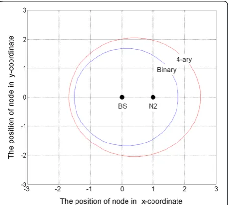
In cooperative networks, the location of source nodes should be taken into consideration so that with increasing distance between the transmitter and the receiver, the transmit power should be utilized for reliable transmissions. The advantage of using network coding is investigated, without loss of generality, in a particular scenario in which a source node N1 is moved around in a two-dimensional (2D) network area (see Figure 4, for example), while BS and the relay node N2 are fixed at given locations. Specifically, BS is located at the origin and N2 at (1, 0) in the 2D space.
The variance of the channel gain between N2 and BS is set as σ2,2d= 1. Consider the location of the source N1 in the
2D space. As previously mentioned in Section 2.2, we make the variance of each channel gain depend on the distance between the two nodes. We use EPA,P1= P2, for both N1
and N2. The location (x,y) of N1 is varied inside the plane. Variances of the channel gains are obtained by
σ2 1;2¼
ffiffiffiffiffiffiffiffiffiffiffiffiffiffiffiffiffiffiffiffiffiffiffiffiffiffiffi x1
ð Þ2þ
y2
q α
;
σ2 1;d¼
ffiffiffiffiffiffiffiffiffiffiffiffiffiffiffi x2þy2 p
α
:
ð24Þ
Based on this 2D setting, the outage probability from the source N1 to BS can readily be analyzed by substi-tuting the variances in the relevant outage expressions given in Section 3.2.
4.1.2. Evaluation of coverage area expansion
The contour of outage probabilities evaluated at 10–4for the source N1 is plotted in Figure 4, where the blue and red lines indicate the results of using the BNC and NBNC-4 schemes, respectively. Figure 4 shows that the position of N1 is expanded by the 4-ary network code. We assumed that the transmit power of both nodes is P1/N0=P2/N0= 20 dB and R1= R2= 1 b/s/Hz. Suppose
that the source N1 is located at (2, 0). Then, the 4-ary network code achieves an outage probability of 10–4 or less, whereas the binary code does not. The contour of the outage probability at 10–4for N1 has been extended with the use of NBNC-4, as compared to the use of BNC.
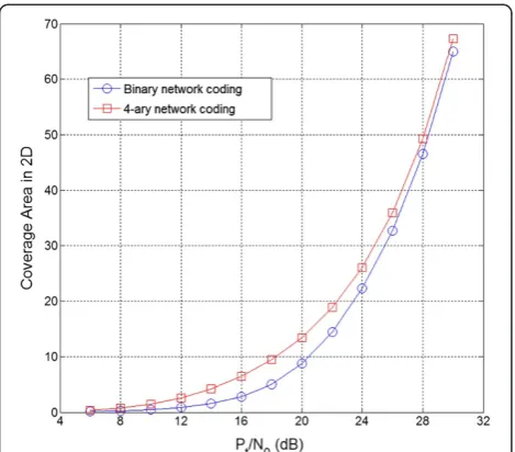
In this study, we define the coverage area of N1 as the geographic area within which the outage probability of N1 is less than a particular level. We evaluate the cover-age area of N1 having a guaranteed outcover-age probability of 10–4for the two different network coding schemes. The results with respect to total transmit power constraints are shown in Figure 5. We assume EPA for both nodes, because OPA results in little improvement, as discussed in the following section. In this case, the coverage area for NBNC-4 is greater than that of BNC. However, in the high SNR region, sayP/N0>25 dB, the effect of the
field size interestingly is small. At a high SNR, the relay is less important since direct transmission from N1 to BS shows good error performance. In the mid SNR region, the effect of field size is the greatest. For example, at 18 dB SNR the coverage area for NBNC-4 is about twofold greater than that for BNC. The low SNR region, in which there is no network coding benefit, is of no further interest.
4.2. OPA
The other power efficiency technique investigated in this study is transmit power allocation. We investigate this
Figure 4Contour plot of the locations of the source node (N1)
problem for the two network codes, using the outage analysis framework developed in Section 3.2.
4.2.1. Formulation of OPA
Hasna and Alouini [2] attempted to minimize outage probability under a total transmit power constraint. Based on a symbol-error-rate analysis with M-PSK and M-QAM modulations, power allocation schemes for DF protocols are presented in [4,20], where the authors considered MRC receivers. A power allocation problem for Nakagami fading channels is considered in [21]. We assume that each node knows all the channel state information by using an appropriate channel feedback scheme. We investigate the outage performance of opti-mal transmit power allocation subject to a total power constraint. In other words, the OPA solution is obtained based on minimization of the outage probability given under a total power constraint.
We use the outage probabilities,Pout, in (20) and (23),
for the BNC and NBNC-4 schemes, to deal with the optimization problem. Note that these are functions of transmit powers, variances of channel gains, and trans-mission rates. Given variances of channel gains and a transmission rate, the optimization problem can be written as follows
Pout P1;P2;σ1;2;σ1;d;σ2;d;R1;R2
¼ min
P1;P2
Pout P1;P2;σ1;2;σ1;d;σ2;d;R1;R2
; ð25Þ
subject to P1+ P2= Pt, P1≥0, and P2≥0, where Pt is
the total transmit power, and P1* and P2* denote the
optimal transmit powers for the two nodes. For the outage probability for the NBNC-4 scheme, the Lagrangian with λas the Lagrange multiplier can be written as
L P1ð ;P2;λÞ ¼ A1 P2
1P2
þ A2 P1P22
þA3 P3 1
þλðP1þP2PtÞ: ð26Þ
Similarly, the Lagrangian for the BNC scheme is
L P1ð ;P2;λÞ ¼ B1 P1P2þ
B2 P2
1P2
þ B3
P1P2 2
þB4
P3 1
þλðP1þP2PtÞ; ð27Þ
for either the binary or the 4-ary network code. Using a first-order derivative condition, the optimal power must satisfy
∂L Pð 1;P2;λÞ
∂P1
¼∂L Pð 1;P2;λÞ
∂P2
¼0: ð28Þ
To find the optimal transmit power P1at the source
for both cooperative schemes, we use the following equations
λN;1P13þλN;2P12þλN;3P1þλN;4¼0; ð29Þ where
λN;1:¼3A13A23A3;λN;2:¼9A3Pt5A1PtþA2Pt;
λN;3:¼2A1Pt29A3P2t;λN;4:¼3A3P3t;;
and λB;1P41þλB;2P13þλB;3P21þλB;4P1þλB;5¼0;
ð30Þ
where
λB;1:¼2B1;λB;2:¼3B23B33B43B1Pt;
λB;3:¼B1Pt2þ9B4Pt5B2PtþB3Pt;
λB;4:¼2B2P2t 9B4Pt2;λB;5:¼3B4Pt3:
For both cases, (29) and (30) correspond to the NBNC-4 and BNC schemes under the total power constraint. We define the ratio of the power allocation as
ρ¼P1 Pt:
ð31Þ
We investigate the effect of variances of channel gains on the optimum ratio of power allocation, while the outage probability is minimized.
4.2.2. Discussion for various link qualities
In this section, we discuss optimal transmit power
allocation for various channel environments. We
consider the position of nodes as follows: source node (N1) is located at coordinate (1, 0), BS is at (0, 0), the relay node (N2) is free to move around in the 2D space.
Figure 5Coverage area of the source node (N1) for the outage
We investigate the effect of the position of the relay node N2 on optimal transmit power allocation. In addition, we aim to investigate the effect of the size of finite fields, used in the underlying network coding scheme, on the results of optimum power allocation.
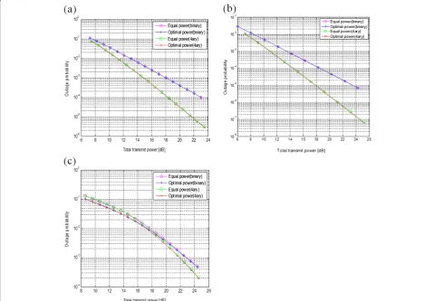
Let us consider three cases, based on the position of N2: (i) N2 is at 0:5;pffiffiffiffiffi3=2 (ii) N2 at (0.5,0), and (iii)
N2 is at (−2,0). From the relation given at the channel model (Section 2.2), the variances of the channel gains can be found as (i)σ1,22 =σ1,2d=σ2,2d= 1, (ii)σ12d= 1,σ1,22 =σ2,2d= 8,
and (iii)σ1,2d= 1,σ1,22 = 0.037,σ2,2d= 0.125, respectively. From
these, one can find the exact outage probabilities by substi-tuting them into (19) and (22). We fix the total transmit power, i.e., Pt=P1+P2at a particular level and show the
outage probability as a function of total transmit power. The corresponding results are shown in Figure 6. Note that in both cases (i) and (ii) the link qualities of the two wire-less channels, i.e., N1-to-N2 and N2-to-BS, are the same and they are good in terms of SNRs. In such cases, as indi-cated by Figure 6a,b, EPA is as good as OPA. In the third case, OPA is obviously better than EPA in general, but this
behavior is substantial only in the low SNR region. From Figure 6c, we note that as the total transmit power increases, the EPA results approach the results of OPA.
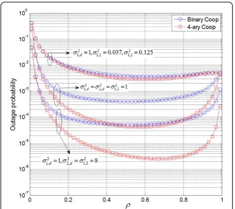
Since it is difficult to see from Figure 6 the amount of difference between EPA and OPA, we now aim to inves-tigate how the outage probability changes as the ratioρ of the transmit power allocation is swept from 0 to 1, while fixing the total transmit power to noise ratio at 20 dB. The result is given in Figure 7. We observe that at around EPA, i.e.,ρ= 0.5, the outage probability is relatively flat, which is reasonable.
Next, we aim to find the optimum ratio ρ when N2,
taking the role of relay for N1, is moved directly on a straight line from BS to N1 and to investigate how much transmit power should be allocated at N1 to obtain the minimum outage probability. Figure 8 shows the results,
where the x-axis indicates the x-coordinate of N2, and
they-axis is the optimumρ.
A noteworthy observation in Figure 8 is that there are two different approaches for obtaining the optimum ratio. One is the analytical approach of solving the optimization problems (29) and (30), which are based on
the approximated outage probabilities (20) and (23). An-other observation is the results obtained from exhaustive numerical evaluations of the exact outage probabilities (19)
and (22) as a function ofρfor both the BNC and NBNC-4
schemes. Note that the results from the two approaches are almost identical. This validates the optimization problem set up in (25).
Now returning to our discussion of the optimum ratioρ, Figure 8 shows that the optimum ratioρis, approximately, less than 0.8 and larger than or equal to 0.5 for the two network coding schemes. In more exact terms, when the relay N2 moves closer to BS, i.e.,x→0, the transmit power P1 rises to 0.78Pt(ρ= 0.78), while the transmit powerP2
for the relay N2 goes to 0.22Pt. 78% of the total transmit
power should be allocated at the source N1 for optimum results. The technical reason for this result is found from close investigation of (20) and (23) approximated, such that the channel variance σ2,2d becomes much larger than the
other fixed parameters, and the approximated outage prob-abilities are dominated mainly by the two terms A1
P2 1P2and
A3
P3 1. Note that P1is taken to the second and third powers in
these terms, whileP2is at its first power. Therefore, it is
easy to see that more power should be allocated toP1than
toP2in order to obtain a smaller outage probability. The
result that more transmit power should be allocated to the source N1 rather than to the relay N2 asx→0 is rea-sonable, since the role of the relay becomes decreasingly critical as it moves away from the source and becomes closer to BS.
On the other hand, we consider the other case in which relay N2 is moved closer to source N1. In the BNC case, we note that the optimal ratio approaches 1/2, i.e., the transmit powersP1andP2approachPt/2. In the NBNC-4
case, however, a very interesting behavior is observed. More transmit powerP1should be used at the source rather than
at the relay to achieve the minimum outage probability. This phenomenon is more interesting with NBNC-4 in the case where relay N2 is closer to source N1.
The optimum ratio increases as the size of the finite field used in network coding is increased from 2 to 4. We can observe from Figure 8 that the optimum ratio of power allocation for the NBNC-4 scheme is generally
much greater than that of the BNC at any position of x.
In other words, more transmit power should be used at source N1 to obtain smaller outage probability. This is
because the combined messages Z1 and Z2 are
max-imally used in NBNC-4. Recall the two different network
coding matrices, H2 for BNC and H4 for NBNC-4,
defined in (1) and (2), respectively. The rank of any (2 × 2) submatrix, i.e., any two rows ofH4, is always 2, while that
of H2 is not always 2 (some may be 1). The crucial
difference between the two network coding schemes can be seen in Case 1 in Section 3.2. This is the outage event considered in (8). With the NBNC-4 scheme, it is possible for only BS to recover the original messagesS1
and S2with the availability of only Z1 and Z2. This is
not possible with the BNC scheme. Figures 7 and 8 show this in detail. In other words, they show how the crucial difference in Case 1 affects the result of OPA, as well as the corresponding outage probability results.
5. Conclusions
In WSNs, sensor nodes operate from finite capacity energy sources, i.e., onboard batteries; thus, designing a system with high power efficiency is a key issue. In this study, the power efficiency is investigated as the size of
Figure 7Outage probability as a function of the power
allocation ratioρatPt/N0= 20 dB.
Figure 8Optimum ratio of power allocation for the position of
finite fields for the linear network coding is increased from 2 to 4, and as the allocation of transmit power, i.e., the power used at the source node versus the power at the relay node, is varied. To evaluate the benefits of these techniques, we derived the outage probability expressions for the considered network coding schemes. We then analyzed the diversity order for the network coding schemes, one with GF(2) and the other with GF(4). Our results indicate that the diversity order using GF(4) is three, but that the diversity order using the binary net-work code is only two. We studied the effects of increased field size on the expansion of the network coverage area. Coverage area expansion by only changing the field size in network coding, without increasing the transmit powers, is a creditable and interesting research result of this study. Our result indicates that the power efficiency benefit of GF(4) as compared to that of GF(2) is substantial and, it manifests not only in increased diversity order but also in noteworthy coverage area expansion.
In future work, it will be meaningful to verify that the proposed NBNC scheme can be extended to a larger-scale network, where more sensor nodes are involved in cooperative transmission.
Competing interest
The authors declare that they have no competing interests.
Acknowledgments
This study was supported by the National Research Foundation (NRF) of Korea grant funded by the Korean government (MEST) (Do-Yak Research Program, No. 2012–0005656, Haek-Sim Research Program, No. 2012–047744).
Received: 30 December 2011 Accepted: 21 November 2012 Published: 22 December 2012
References
1. J. Luo, R.S. Blum, L.J. Cimini, L.J. Greestein, A.M. Haimovich, Decode-and-forward cooperative diversity with power allocation in wireless networks, in
IEEE Global Telecommunications Conference (GLOBECOM), 2005(St. Louis, USA, 2005), pp. 3048–3052
2. M.O. Hasna, M.S. Alouini, Optimal power allocation for relayed transmission over Rayleigh-Fading channels. IEEE Trans Wirel Commun3(6), 1999–2004 (2004) 3. R. Annavajjala, P.C. Cosman, L.B. Milstein, Statistical channel knowledge-based optimal power allocation for relaying protocols in the high SNR regime. IEEE J. Sel. Areas Commun.25(2), 292–305 (2007)
4. W. Su, A.K. Sadek, K.J.R. Liu, SER performance analysis and optimum power allocation for decode-and-forward cooperation protocol in wireless networks, inIEEE Wireless Communications and Network Conference (WCNC), 2005(New Orleans, USA, 2005), pp. 984–989
5. N. Ahmed, M. Khojastepour, B. Aazhang, Outage minimization and optimal power control for the fading relay channel, inIEEE Information Theory Workshop (ITW), 2004(San Antonio, USA, 2004), pp. 458–462 6. J.N. Laneman, D.N.C. Tse, G.W. Wornell, Cooperative diversity in wireless
networks: efficient protocols and outage behavior. IEEE Trans Inf Theory 50(12), 3062–3080 (2004)
7. R. Ahlswede, N. Cai, S.Y.R. Li, R.W. Yeung, Network information flow. IEEE Trans Inf Theory46(4), 1204–1216 (2000)
8. M. Yu, J. Li, R.S. Blum, User cooperation through network coding, inIEEE International Conference on Communications (ICC), 2007(Glasgow, Scotland, 2007), pp. 4064–4069
9. C. Peng, A. Zhang, M. Zhao, Y. Yao, W. Jia, On the performance analysis of network-coded cooperation in wireless networks. IEEE Trans Wirel Commun 7(8), 3090–3097 (2008)
10. X. Bao, J. Li, Adaptive network coded cooperative (ANCC) for wireless relay networks: matching code-on-graph with network-on-graph. IEEE Trans Wirel Commun7(2), 574–583 (2008)
11. B. Du, J. Zhang, Parity-check network coding for multiple access relay channel in wireless sensor cooperative communications. EURASIP J Wirel Commun Netw2010, 1–15 (2010)
12. D. Duyck, D. Capirone, J.J. Boutros, M. Moeneclaey, Analysis and construction of full-diversity joint network-LDPC codes for cooperative communications. EURASIP J Wirel Commun Netw2010, 1–16 (2010) 13. L. Xiao, T.E. Fuja, J. Kliewer, D.J. Costello, A network coding approach to
cooperative diversity. IEEE Trans Inf Theory53(10), 3714–3722 (2007) 14. T.E. Hunter, S. Sanayei, A. Nosratinia, Outage analysis of coded cooperation.
IEEE Trans Inf Theory52(2), 375–391 (2006)
15. Y. Chen, S. Kishore, J. Li, Wireless diversity through network coding, inIEEE Wireless Communications and Network Conference (WCNC), 2006(Las Vegas, USA, 2006), pp. 1681–1686
16. D.H. Woldegebreal, H. Karl, Network-coding based adaptive decode and forward cooperative transmission in a wireless network: outage analysis, in
Proc. IEEE European Wireless Conference, 2007(Paris, France, 2007), pp. 1–6 17. M. Xiao, M. Skoglund, Multiple-user cooperative communications based on
linear network coding. IEEE Trans Commun58(12), 3345–3351 (2010) 18. J.L. Rebelatto, B.F. U-Filho, Y. Li, B. Vucetic, Multi-user cooperative diversity
through network coding based on classical coding theory. IEEE Trans Signal Process60(2), 916–926 (2012)
19. H. Topakkaya, Z. Wang, Wireless network code design and performance analysis using diversity-multiplexing tradeoff. IEEE Trans Commun59(2), 488–496 (2011)
20. W. Su, A.K. Sadek, K.J. Ray Liu, Cooperative communications in wireless networks: performance analysis and optimum power allocation. Wirel. Personal Commun.59, 181–217 (2008)
21. Y. Lee, M.H. Tsai, S.I. Sou, Performance of decode-and-forward cooperative communications with multiple dual-hop relays over Nakagami-mfading channels. IEEE Trans Wirel Commun8(6), 2853–2859 (2009)
doi:10.1186/1687-1499-2012-366
Cite this article as:Seong and Lee:4-ary network coding for two nodes in cooperative wireless networks: exact outage probability and coverage expansion.EURASIP Journal on Wireless Communications and Networking20122012:366.
Submit your manuscript to a
journal and benefi t from:
7Convenient online submission
7Rigorous peer review
7Immediate publication on acceptance
7Open access: articles freely available online
7High visibility within the fi eld
7Retaining the copyright to your article