e-ISSN: 2278-067X, p-ISSN: 2278-800X, www.ijerd.com
Volume 10, Issue 7 (July 2014), PP.63-68
Surface modification of EDM process using Carbon
Nano tubes, A Review
Amandeep Singh
1, Neel Kanth grover
2, Parminderjit singh
31Assistant professor, Department of Mechanical Engg, FCET Ferozshah 2Associate professor, Department of Mechanical Engg, SBSSTC Ferozepur)
3
Associate professor, Department of Mechanical Engg, FCET Ferozshah
Abstract:- Better surface finish demand is increasing from recent years for machining of tough and super alloys. Traditionally EDM Dielectric is mixed with either aluminum (Al), chromium (Cr), copper (Cu), and silicon carbide (SiC) powder to obtain high surface finish value. In new technology researchers mix Carbon nano tube (CNT) with dielectric fluid in EDM process because of high thermal conductivity of CNTs. The analysis of surface characteristics like surface roughness, micro cracks of work pieces are carried out and an excellent machined nano surface finish is attained.
Keywords:- CNT, EDM, MWNT,PHEDM, SWNT, SR,
I.
INTRODUCTION
Electrical-discharge machining is generally employed for machining of hard and tough materials; so-called difficult-to-machined materials.EDM is used for production of complicated shapes and dies with high accuracy[1-3]. The work piece and the electrode do not directly contact with each other, thus eliminating the force-induced chatter or vibration problems and allowing small or thin components to be machined without causing distortion [4-5]. The spark between the tool and work piece produces a very high temperature on the work piece surface, and removes the material by melting and vaporization. A small amount of molten layer is expelled from the surface, while the residual melted layer that is not flushed out by the dielectric fluid is later solidified on the work piece surface as recast layer. The electrical-discharge often will induce machining defects such as craters, micro cracks, micro voids and pockmarks on the surface layer leading to low surface finish value [6-7]. Although an excellent machined finish can be obtained by setting the EDM parameters at a low pulsed current and a small pulse on-time to improve strength but this approach is more time consuming. In general, the conventional machining processes such as grinding, polishing, and lapping are adopted to remove the surface damage layer induced by EDM process. These operations will cause excessive tool wear and expensive.
II.
CARBON NANO TUBES
Carbon nanotubes are one of the most commonly mentioned building blocks of nanotechnology. With one hundred times the tensile strength of steel, thermal conductivity better than all but the purest diamond, and electrical conductivity similar to copper, but with the ability to carry much higher currents, they seem to be a wonder material. Carbon nano tubes were discovered in 1991 by Sumio Iijima of NEC and are effectively long, thin cylinders of graphite, which in turn is made up of layers of carbon atoms arranged in a hexagonal lattice, like chicken wire as shown in figure 1. Though the chicken wire structure itself is very strong, the layers themselves are not chemically bonded to each other but held together by weak forces called Vander Waals. It is the sliding across each other of these layers that gives graphite its lubricating qualities and makes the mark on a piece of paper as you draw your pencil over it. Now imagine taking one of these sheets of chicken wire and rolling it up into a cylinder and joining the loose wire ends. The result is a tube that was once described by Richard Smalley
III.
TYPES OF NANO TUBES
Carbon nanotubes are generally of two types, single-walled varieties (SWNTs), which have a single cylindrical wall as in Figure 2, and multi-walled varieties (MWNTs), which have cylinders within cylinders as in figure 5. The lengths of both types vary greatly, depending on the way they are made, and are generally microscopic rather than nanoscopic, i.e. greater than 100 nanometers (a nanometer is a millionth of a millimeter). The aspect ratio (length divided by diameter) is typically greater than 100 and can be up to 10,000, but recently even this was made to look small. In May last year SWNT strands were made in which the SWNTs were claimed to be as long as 20 cm. Even more recently, the same group has made strands of SWNTs as long as 160 cm, but the precise make-up of these strands has not yet been made clear.
A. Single-Walled Carbon Nanotubes (Swnts)
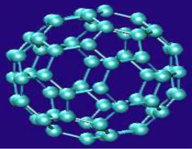
SWNTs are best nano tubes but major drawback of these is that difficult to make as compared to Multi wall nano tubes. These have amazing properties. these are basically tubes of graphite and are normally capped at the ends as shown in figure 3, although the caps can be removed. The caps are made by mixing in some pentagons with the hexagons and are the reason that nanotubes are considered close cousins of buckminsterfullerene as shown in figure 4, a roughly spherical molecule made of sixty carbon atoms, that looks like a soccer ball and is named after the architect Buckminster Fuller (the word fullerene is used to refer to the variety of such molecular cages, some with more carbon atoms than buckminsterfullerene, and some with fewer). Discussions of the electrical behavior of carbon nanotubes usually relate to experiments on the single-walled variety. As we have said, they can be conducting, like metal (such nanotubes are often referred to as metallic nanotubes), or semiconducting, which means that the flow of current through them can be stepped up or down by varying an electrical field.
Fig. 2: Single wall nano tube Fig. 3: Simulated structure of a carbon nanotube.
Fig. 4: Buckminsterfullerene.
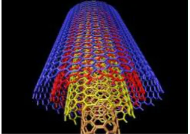
B. Multi-Walled Carbon Nanotubes (Mwnts)
names such as bamboo-trunks, sea urchins, necklaces or coils, have also been observed under different processing conditions. The variety of forms may be interesting but also has a negative side. MWNTs always have more defects than SWNTs and these diminish their desirable properties.
Fig. 5: Representaion of a multi-walled carbon nanotube Fig. 6: Multi wall carbon nano tube
IV.
NANOTUBE GEOMETRY
There are three unique geometries of carbon nanotubes. The three different geometries are also referred to as flavors. The three flavors are armchair (Fig 7), zig-zag (Fig 8), and chiral (Fig 9) [e.g. zig-zag (n, 0); armchair (n, n); and chiral (n, m)]. These flavors can be classified by how the carbon sheet is wrapped into a tube (see pictures below).
Fig. 7: Armchair arrangement of carbon atoms Fig. 8: Zig-zag arrangement of carbon atoms
Fig. 9: Chiral arrangement of carbon atoms
V.
EDM WITH CARBON NANO TUBES
materials. By using graphite, silicon (Si), aluminum (Al), crushed glass, silicon carbide (SiC) and molybdenum sulphide with different grain size, Al powder has been reported to give mirror finish for SKH-51 work pieces, but not on SKH-54 work pieces [14]. Powder properties has great influence on the Surface Quality of SKD-11 work piece using Al, chromium (Cr), Copper (Cu), and SiC powders. The smallest particle (70–80 nm) generates best surface finish and Al powder produces the best surface finish. The suspended powder such as graphite (Gr) and silicon (Si) distributed in the dielectric can cause the effect of lowering the breakdown voltage so that the discharges can occur at a wider inter electrode gap, which facilitates flushing debris and reducing servo hunting so that machining is more stable with improved machining efficiency [16-17]. When the silicon powder is used, the surface roughness can be significantly reduced allowing the generation of mirror-like surfaces. The presence of silicon in the dielectric can eliminate the undesirable discharge conditions [18]. The particle size, the particle concentration, the particle density, the electrical resistivity and the thermal conductivity of powder are important characteristics that significantly affect the machining performance in EDM process [19]. silicon powder showed a positive influence in the reduction of the operating time required to achieve a specific surface quality, and in the decrease of the surface roughness, allowing the generation of mirror-like surfaces [20]. It is necessary to optimize the process parameters of powder mixed electrical discharge machining (PMEDM) like Pulse on time, duty cycle, peak current and concentration of the silicon powder added into the dielectric fluid of EDM to reduce the roughness [21]. While the smallest particles generate the best surface finish of the EDM work, literature also shows that powders of lower density, lower electrical resistivity and excellent thermal conductivity will benefit to improve the machining performance in the EDM process [22]. The graphite, aluminium and alumina nanopowders mixed in dielectric on micro EDM of tool steel (SKH-51) and tungsten carbide (WC). The results show the presence of a conductive or semi-conductive nanopowder lowers the breakdown strength and increases the spark gap during powder-mixed micro-EDM. The surface finish and topography is improved significantly owing to the increased spark gap and uniform discharging. In addition, the lower breakdown strength of dielectric and increased spark gap contribute to higher MRR, lower tool wear, and better surface finish [23-24]. Mixing of boron carbide powder in deionized water dielectrics enhances machining performance in micro-EDM of Ti-6Al-4V alloy [25]. Silicon powder concentrations, peak current and pulse duration play important roles in improving the surface quality in EDM of metal matrix composites, while the supplied voltage is an insignificant variable [26]. The Al particle size and concentration significantly affect machining efficiency during EDM of Inconel 718 [27]. Recently, the nano powder-mixed EDM plays an important role in improving EDM performance. Before 2010's, the improvement of surface finish of EDM specimen was mainly by the use of micro powders (such as Al, Cr, Cu, SiC, Gr). However, owing to their heavy specific gravity these result in non-uniform dispersion in the dielectric. The graphite nano-powder-mixed in the dielectric resulted in 20-30% reduction in surface roughness of WC-Co (Figure 10), lower the breakdown strength and facilitate the ignition process thus improving the material removal rate [28]. The reduction of 35% in machining time was obtained after using nano MoS2 and nanographite powders suspension in dielectric fluid [29-30].
Fig. 10 : (a) die-sinking, without nano-powder (b) die-sinking, with nano-powder
materials and homogeneous distribution of CNTs in the matrix are important factors for micro-EDM of Al2O3/CNTs hybrid composites [34]. The AISI D2 tool steel sparked by SWCNTs has better surface finish and better surface morphology as compared with specimens sparked without SWCNTs. The SWCNTs can absorb the heat from electrical discharged material and minimize the white layer formed in the work piece. A nano finish can be obtained by setting the machining at low pulse energy [35-36]. The surface roughness of the work piece and the machining efficiency of the EDM with powder mixed into the dielectric were improved by 70% and 66% respectively, compared with conventional EDM.CNTs demonstrate better achievement than other powder.[37]
Fig. 11: SEM micrographs of the machined surface in use of dielectrics of (a) kerosene and (b) kerosene+CNTs
Comparsion of roughness obtained by different dielectric is shown in Table 1. By using nano material especially multi wall carbon nano tube in the machining process like grinding, the surface characteristics can be improve from micro to nano level [38].
Table 1: Roughness obtained by different dielectric [38]
Field emission scanning electron microscope (FESEM) study reveals that the electrical conductivity has a increasing tendency as the CNTs content is increased in aluminum oxide (Al2O3) and has a critical point at 5% Al2O3 (volume fraction). Further homogeneous distribution of CNTs in the matrix is important factors for micro-EDM of Al2O3/CNTs hybrid composites [39].
VI.
CONCLUSIONS
From the Literature it is concluded that using carbon nano tube as dielectric in EDM process, surface finish can be enhanced to great level. Further there should be optimization of various EDM process parameters to achieve the better surface characteristics.
REFERENCES
[1]. J. Y. Kao, C. C. Tsao, S. S. Wang and C. Y. Hsu, Int. J. Adv. Manuf. Tech. 47, 395 (2010). [2]. S. Singh, S. Maheshwari, A. Dey and P. C. Pandey, Int. J. Manuf. Tech. Manage. 21, 67 (2010). [3]. K. M. Patel, P. M. Pandey and P. V. Rao, J. Eng. Mater. Technol, T. ASME 133, (2011). [4]. T. Y. Tai and S. J. Lu, Int. J. Fatigue 31, 433 (2009).
[5]. J. Marafona and C. Wykes, Int. J. Mach. Tool. Manu. 40, 153 (2000). [6]. Y. H. Guu and H. Hocheng, Int. J. Mater. Prod. Tec. 16, 642 (2001).
[7]. Y. H. Guu, H. Hocheng, C. Y. Chou and C. S. Deng, Mat. Sci. Eng. A 358, 37 (2003). [8]. B.-H. Yan and S.-L. Chen, J. Chin. Soc. Mech. Eng. 14, 307 (1993).
[9]. H.-M. Chow, B.-H. Yan, F.-Y. Huang and J.-C. Hung, J. Mater. Process. Tech. 101, 95 (2000). [10]. B. H. Yan, Y. C. Lin, F. Y. Huang and C. H. Wang, Mater. Trans. 42, 2597 (2001).
[11]. Q. Y. Ming and L. Y. He, J. Mater. Process. Tech. 52, 44 (1995).
[12]. H. K. Kansal, S. Singh and P. Kumar, J. Mater. Process. Tech. 184, 32 (2007).
Samples Ra Values (μm)
Sample1(with no lubricant) 0·251
Sample2(with water soluble oil) 0·137
Sample3(with SAE20W-40) 0·096
Sample4 (with SAE20W-40 +
MWCNT)
[13]. F. Hu, B. Y. Song, Y. F. Guo, X. D. Yang, J. C. Bai and D. Li, " Study on powder mixed EDM of an aluminium matrix composite", 2011 International Conference on Environmental Biotechnology and Materials Engineering, EBME 2011, March 26, 2011 - March 28, 2011, (Harbin, China) pp1947-1951. [14]. Y.S. Wong, L.C. Lim, I. Rahuman, W.M. Tee, Near-mirror-finish phenomenon in EDM using
powder-mixed dielectric, Journal of Materials Processing Technology 79 (1998) 30–40.
[15]. T. Yih-fong, C. Fu-chen, Investigation into some surface characteristics of electrical discharge machining SKD-11 using powder suspension dielectric oil, Materials Processing Technology 170 (2005) 385–391.
[16]. Y. S. Wong, L. C. Lim, I. Rahuman and W. M. Tee, J. Mater. Process. Tech. 79, 30 (1998). 71
[17]. W. S. Zhao, Q. G. Meng and Z. L. Wang, " The application of research on powder mixed EDM in rough machining", 10th International Manufacturing Conference in China (IMCC 2002), October 11, 2002 - October 11, 2002, (Fujian, China) pp30-33.
[18]. P. Pecas and E. Henriques, Int. J. Mach. Tool. Manu. 43, 1465 (2003). [19]. Y. F. Tzeng and C. Y. Lee, Int. J. Adv. Manuf. Tech. 17, 586 (2001).
[20]. Pecas “Influence of silicon powder-mixed dielectric on conventional electrical discharge machining International” J. Machine Tools Manuf 43 (2003) 1465-1471.
[21]. Kansal H.K “Parametric optimization of powder mixed EDM by response surface methodology” Journal of Materials Processing Technology. Volume 169, Issue 3(2005) 427–436.
[22]. T. Yih-Fong and C. Fu-Chen, J. Mater. Process. Tech. 170, 385 (2005).
[23]. M. P. Jahan, M. M. Anwar, Y. S. Wong and M. Rahman, Proceedings of the Institution of Mechanical Engineers, Part B: Journal of Engineering Manufacture 223, 1127 (2009).
[24]. M. P. Jahan, M. Rahman and Y. S. Wong, Proceedings of the Institution of Mechanical Engineers, Part B: Journal of Engineering Manufacture 224, 1725 (2010).
[25]. G. Kibria, B. R. Sarkar, B. B. Pradhan and B. Bhattacharyya, Int. J. Adv. Manuf. Tech. 48, 557 (2010). [26]. H. Kumar and J. P. Davim, J. Compos. Mater. 45, 133 (2011).
[27]. A. Kumar, S. Maheshwari, C. Sharma and N. Beri, Mater. Manuf. Process. 26, 1011 (2011). [28]. M. P. Jahan, M. Rahman and Y. S. Wong, Int. J. Adv. Manuf. Tech. 53, 167 (2011).
[29]. G. S. Prihandana, T. Sriani, K. Prihandana, Y. Prihandana, M. Mahardika, M. Hamdi and K. Mitsui, " Study on the effect of nano and micro MoS2 powder in micro-electrical discharge machining", International Conference on Advances in Materials and Processing Technologies, AMPT 2009, October 26, 2009 - October 29, 2009, (Malaysia) pp1450-1455.
[30]. G. S. Prihandana, M. Mahardika, M. Hamdi, Y. S. Wong and K. Mitsui, Int. J. Adv. Manuf. Tech. 56, 143 (2011).
[31]. H. Y. Miao, J. T. Lue and M. S. Ouyang, " Surface modification by electric discharge implemented with electrodes composed of carbon nanotubes", pp1375-1380.
[32]. C. Mai, H. Hocheng and S. Huang, Int. J. Adv. Manuf. Tech., 1 (2011). [33]. S. Prabhu and B. K. Vinayagam, Arch. Civil Mech. Eng. 11, 149 (2011).
[34]. H.-S. Tak, C.-S. Ha, H.-J. Lee, H.-W. Lee, Y.-K. Jeong and M.-C. Kang, T. Nonferr. Metal. Soc. China 21, s28 (2011).
[35]. S. Prabhu and B. K. Vinayagam, Int. J. Mach. Machina. Mater. 10, 99 (2011). [36]. S. Prabhu and B. K. Vinayagam, Int. J. Comput. Mater. Sci. Surf. Eng. 4, 23 (2011).
[37]. C. Mai & Hong Hocheng” Advantages of carbon nanotubes in electrical discharge machining Int J Adv Manuf Technol DOI 10.1007/s00170-011-3476-2 (2011)
[38]. “s prabhu1, b k vinayagam” Nano surface generation of grinding process using carbon nano tubes [39]. Vol. 35, Part 6, December 2010, pp. 747–760

![Table 1: Roughness obtained by different dielectric [38]](https://thumb-us.123doks.com/thumbv2/123dok_us/1389664.1650130/5.595.114.496.183.304/table-roughness-obtained-different-dielectric.webp)
