Functional Delay Test Generation Approach Using
a Software Prototype of the Circuit
Eduardas Bareiša, Vacius Jusas, Kęstutis Motiejūnas, and Rimantas Šeinauskas
Software Engineering Department, Kaunas University of Technology, Studentu 50, 51390 Kaunas, Lithuania
{eduardas.bareisa, vacius.jusas, kestutis.motiejunas, rimantas.seinauskas}@ktu.lt
Abstract. The paper presents functional delay test generation approach for non-scan synchronous sequential circuits. The non-scan sequential circuit is represented as the iterative logic array model consisting of k copies of the combinational logic of the circuit. The value k defines the number of clock cycles. The software prototype model is used for the representation of the function of the circuit. The faults are considered on the inputs and on the outputs of the model only. The random input stimuli are generated and selected then according to the proposed approach. The experimental results demonstrate the superiority of the delay test stimuli generated at the functional level using the introduced approach against the transition test stimuli obtained at the gate level by deterministic test generator. The functional delay test generation approach especially is useful for the circuits, when the long test sequences are needed in order to detect transition faults.
Keywords: functional delay test generation, software prototype, non-scan sequential circuit.
1.
Introduction
the length of scan register, some faults, which have no influence to the function of the circuit, can be detected [1]. As a consequence, the scan register cannot be applied for all the circuits. Therefore, the test generation methods for the circuits in non-scan mode, which are the object of our research, have their value, as well.
One of ways to improve test generation methods is the higher level of the abstraction of the circuit model. Such an approach has the following advantages: the lesser number of faults, the possibility to generate test without waiting synthesized structural description of the circuit, the ability to obtain test earlier in the design cycle, the lesser pressure of time-to-market during the test generation. The circuit model at the higher level of the abstraction can be written either in hardware description language or in high level programming language. We call such a model a software prototype model. The use of the software prototype model restricts the abilities of the test generation. There is no possibility according to the value at the output select the values at the inputs. The software prototype model allows one way calculation only – according to the values at the inputs to calculate the responses at the outputs. Therefore, the base for test generation using the software prototype model is random stimuli generation and functional fault model.
The contributions of this paper are as follows:
We summarize the acquired experience in functional delay test generation for non-scan sequential circuits and present a generic approach of functional delay test generation for non-scan sequential circuits using software prototype model;
We deliver the detailed algorithm of functional delay test generation;
We suggest a fault model and develop a concept of preliminary test selection.
The remainder of the paper is organized as follows. We analyze related work in Section 2. We present the functional fault model in Section 3. We investigate the possibilities of test generation in Section 4. We develop the concept of preliminary test selection in Section 5. We conclude in Section 6.
2.
Related Work
propagate the fault effects to the primary outputs. Therefore, the fault effect can span several clock cycles.
The fault models for delay test generation were suggested in [2, 3, 4]. The authors consider transition faults, and test is applied at-speed. At-speed test application has the advantage that the circuit is tested under its normal operation conditions. It was demonstrated in [5], a test application, which deviates from normal operation, can cause faulty behavior that would not show up during normal operation.
Transition faults are used for their simplicity in modeling spot defects that affect delays either at the inputs or the outputs of gates [2]. When at-speed tests are used, a faulty line is considered under multiple consecutive fast clock cycles.
Pomeranz and Reddy suggested an unspecified transition fault model in [2] and further elaborated it in [3]. Under this model, unspecified values are introduced into the faulty circuit when fault effects may occur. Fault detection potentially occurs when an unspecified value reaches a primary output. Due to the uncertainty that the unspecified value will be different from the fault-free value, an added requirement to this model is that a fault would be detected multiple times.
The model [4] requires the activation of single stuck-at faults with opposite stuck-at values on the same line g at consecutive time units. In addition, it requires the detection of both faults as single faults at the same or later time units. Due to the activation of the faults at consecutive time units, there is a transition at the fault site g. Since both faults are eventually detected, a deviation from the expected value at either the first or second time unit due to a delay fault on g or due to transitions that started earlier and did not settle will be detected. The authors [4] suggest using this model as supplementary one together with other models to increase the confidence that delay defects will be detected.
The delay fault test for non-scan synchronous sequential circuit could be constructed at the functional level using the software prototype model [6-9]. Kang et al. [6] suggested the input/output transition (TRIO) fault model for functional test selection at the register-transfer level (RTL). The model is defined with respect to the primary inputs, primary outputs, and state variable of the module. But this model is approximate due to the following reasons: 1) it does not stipulate toggle propagation all the way to the primary outputs; 2) the evaluation of the transition at the output, which depends on multiple input transitions, is too much optimistic. Therefore, the presented experimental results demonstrate quite a large loss of transition fault coverage of the initial test pool.
Bareiša et al. [7] introduced three different new functional fault models. According to the proposed models, the functional faults are considered on the primary inputs and primary outputs of the model only. The number of functional faults is independent of the number of clock cycles.
The non-scan sequential circuit is represented as the iterative logic array model consisting of k copies of the combinational logic of the circuit. The value k defines the number of clock cycles. The experimental results demonstrate the superiority of the delay test stimuli constructed at the functional level using the functional fault models over the transition test stimuli generated at the gate level by deterministic test generator. But the method [8] is not efficient for large and complex circuits.
The idea of functional delay fault model [8] was explored further and developed in [9]. The goal of the research was the efficiency of the model, which finally was expressed in the obtained delay fault coverage. The authors suggested two functional fault models, namely, pin pair state (PPS) fault model and pin pair full state (PPFS) fault model. In order to investigate the proposed fault models the authors chose two different implementations: forward propagation and backward propagation. The experiments did not reveal the single best model. After consideration, the authors chose the one for the future experiments. That is the PPFS fault model in the implementation of the backward propagation. The details of this fault model and implementation will be presented in Section 3.
For synchronous sequential circuits, one important issue is their initialization, which means the sequential circuit must start from a known initial state for it to operate correctly, as well as when generating tests for circuit, or when verifying the functional properties. The papers [10, 11] address this issue.
In the paper [10], a heuristic search method for logical initialization problem based on Max Min Ant System is presented. The algorithm employs a collection of agents that collaborate to explore the primary input search graph. The limitation of this algorithm is that it is not able to identify uninitializable flip-flops.
A method for finding shortest length reset sequences using a software prototype of the circuit is proposed in [11]. The novelty and research value of the proposed method comes from using software that emulates circuit instead of using manufactured chip. Such a method does not use logical structure of the chip itself and test generation may start earlier in the manufacturing process.
The functional test sequences are long [8] and it is very time-consuming to evaluate the quality of functional test sequences by gate-level fault simulation. Several authors [12, 13, 14] suggested estimating the fault coverage of functional test sequences without fault simulation.
Pomeranz et al. [12] described a stuck-at fault coverage metric based only on logic simulation of the gate level circuit. The metric is based on the set of states that the circuit traverses under the test sequence. The authors [12] defined several versions of the metric suitable for different applications. Experimental results demonstrated the effectiveness of the metric for ranking of test sequences based on their fault coverage.
Scheduler module of the Illinois Verilog Model showed that the deviations metric is computationally efficient and it correlates well with gate-level coverage for stuck-at, transition-delay, and bridging faults.
Vinutha et al. [14] described a metric to grade the test sequence using instruction-execution graph. The metric is based on the set of registers the circuit traverses under the test sequence. Using this information in combination with the observability and controllability of the register, the test sequence is graded. Experimental results on Parwan processor showed the effectiveness of the metric in ranking the test sequence based on their fault coverage.
We are going to use the idea of estimating functional test subsequences without fault simulation in the functional delay test generation. The idea will be clarified in Section 5. We present functional delay fault model in the next section.
3.
Functional Delay Fault Model
We provide a brief presentation of the main concepts of the functional delay fault model [9].
Definition 1. The test subsequence is a sequence of input stimuli, which starts with a set of initialization stimuli, and the length of test subsequence is equal to the defined number of clock cycles.
Let a circuit have a set of primary inputs X = {x1, ..., xi, ..., xn}, a set of primary outputs Y = {y1, ..., yj, ..., ym}, a set of bits of previous state Q = {q1, ..., qj, ..., qv}, and a set of bits of next state P = {p1, ..., pj, ..., pv}. The number v is the same for the bits of previous and next states. Therefore, the input stimulus has n+v signal values, and the output stimulus has m+v signal values. The circuit is considered as the one cell of the iterative logic array. The cells are connected into the chain. The connection is formed in the following way: the previous state bits of cell i are connected to the next state bits of cell i-1; the next state bits of cell i are connected to the previous state bits of cell i+1. The number k of clock cycles in the test subsequence defines the number of the cells in the iterative logic array.
The functional fault is described by a pair of stuck-at faults, where the first member of the pair is the stuck-at fault at the inputs, and the second member of the pair is the stuck-at fault at the outputs. We consider the following pairs: (xif, yjh), (qif, yjh), (xif, pjh) and (qif, pjh), f=0,1, h=0,1.
Definition 2. The functional delay fault (xi f
, yj h
) is detected by test stimulus S under the following conditions:
1. The test stimulus S detects the single fault xi stuck-at f on the primary input of the cell t.
3. In the presence of xi stuck-at f on the primary input of the cell t, the value at the primary output yj of the cell t or the cells t+1, t+2, …, k is h. 4. The fault-free value under S at the primary input xi of the cell t-1 is f.
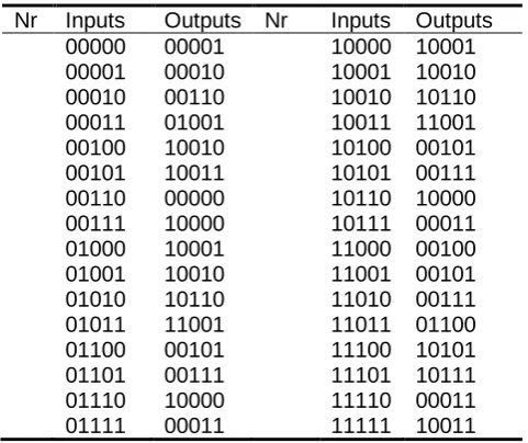
For illustration purposes, we consider ITC’99 [15] benchmark circuit b01. The circuit has two primary inputs, three state variable, and two primary outputs. We do not include the reset and clock signals into the number of the primary inputs. A behavioral description of the circuit b01 has three state bits; meanwhile the synthesized implementation at the structural level has five flip-flops. Two additional flip-flops form the buffer zone at the primary outputs, and they have no impact on the functions of the circuit.
A truth table of one copy of circuit b01 is shown in Table 1. The numbers in the columns under name Nr specify the number of input stimuli. The input stimuli are reported in the columns under name Inputs. The first two bits of the input stimuli denote the primary inputs, the others three bits denote the previous state bits. The obtained responses are given in the columns under name Outputs. The first two bits of the response denote the primary outputs, the others three bits denote the next state bits.
Table 1. Truth table of b01
Nr Inputs Outputs Nr Inputs Outputs 00000 00001 10000 10001 00001 00010 10001 10010 00010 00110 10010 10110 00011 01001 10011 11001 00100 10010 10100 00101 00101 10011 10101 00111 00110 00000 10110 10000 00111 10000 10111 00011 01000 10001 11000 00100 01001 10010 11001 00101 01010 10110 11010 00111 01011 11001 11011 01100 01100 00101 11100 10101 01101 00111 11101 10111 01110 10000 11110 00011 01111 00011 11111 10011
The truth table of b01 is provided that the reader could validate the simulation results provided in Table 2.
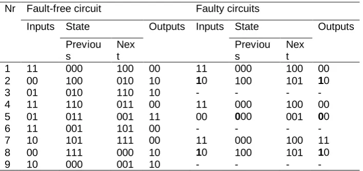
outputs. They are shown in the columns under names Previous, Next, and Outputs, respectively. The first two rows of the faulty circuit present the simulation results of stuck-at 1 fault at the x1. The obtained changes in comparison with fault-free circuit are shown in bold. The fault is detected at the first output. Therefore, there is no meaning to simulate further. According to Definition 2, the functional delay fault (x11, y11) is detected by the given test subsequence.
Table 2. Fault simulation results
Nr Fault-free circuit Faulty circuits
Inputs State Outputs Inputs State Outputs
Previou s
Nex t
Previou s
Nex t
1 11 000 100 00 11 000 100 00
2 00 100 010 10 10 100 101 10
3 01 010 110 10 - - - -
4 11 110 011 00 11 000 100 00
5 01 011 001 11 00 000 001 00
6 11 001 101 00 - - - -
7 10 101 111 00 11 000 100 11
8 00 111 000 10 10 100 101 10
9 10 000 001 10 - - - -
Definition 3. The functional delay fault (qif, yjh) is detected by test stimulus S under the following conditions:
1. The test stimulus S detects the single fault qi stuck-at f on the previous state bit of the cell t.
2. The fault-free value under S at the primary output yj of the cell t or the
cells t+1, t+2, …, k is –h.
3. In the presence of qi stuck-at f on the previous state bit of the cell t, the value at the primary output yj of the cell t or the cells t+1, t+2, …, k is h. The rows 4 and 5 of Table 2 illustrate the simulation of stuck-at 0 fault at the q1. The fault is detected at the first output. According to Definition 3, the functional delay fault (q1
0 , y1
0
) is detected by the given test subsequence. 4. The fault-free value under S at the previous state bit qi of the cell t-1 is
f.
Definition 4. The functional delay faults (xi f
, pj h
) and (qi f
, pj h
) are detected by test stimulus S under the following conditions:
1. The functional delay faults (xif, pjh) and (qif, pjh) satisfy the conditions of Definition 2 and Definition 3, respectively, and they are detected at the output pj of cell t.
2. The functional delay fault (qi f
, yj h
be detected according to the conditions of Definition 3, except the fourth condition.
The rows 7 and 8 of Table 2 illustrate the simulation of stuck-at 1 fault at the x1. The fault invokes changes at all the next state bits. According to condition 2 of Definition 4, we have to consider the detection of the following faults: q1
1 , q2
0 , q3
1
at the primary outputs. Using the truth table of b01, we can determine that the functional delay faults (x11, q11), (x11, q20), (x11, q31) are detected by the given test subsequence.
We term the functional delay faults defined in Definitions 2-4 by a pin pair full state (PPFS) functional delay faults.
The detection of the functional delay faults can be represented by a detection matrix D=||da,b||2*(n+v),2*(m+v), where index a is used to denote the inputs of the circuit, and index b is used to denote the outputs of the circuit.
We can implement the delay test generation program using the PPFS functional fault model in several ways. We have chosen two ways. They are symbolically named as forward and backward computations. After analysis of the experimental results [9], we have chosen the algorithm of the backward computation as the most appropriate mode of the implementation for the future experiments. We provide some details of this implementation.
The implementation consists of two phases: 1. Formation of the activity vector.
2. Fault simulation.
The goal of the first phase is to form the activity vector, the elements of which indicate the activity of previous state bits of the iterative logic array. The bit is active, if the fault effect injected at this bit is observed at the primary output. We are interested in the fact only whether the fault effect, which propagates from the previous state bit, is observed at the primary outputs. We are not interested in at which outputs the fault effect is observed. Therefore, the activity vector is formed. The entry of the activity vector, which corresponds to the previous state bit, is flagged, if this bit belongs to the fault effect propagation path to the primary output.
In order to form the activity vector, the test subsequence is simulated in the fault-free mode. We start the formation of the activity vector from the last test stimulus in the test subsequence. The value of each previous state bit is complemented in turn and simulated. We obtain v faulty test stimuli. The responses are measured at the primary outputs and the next state bits. But the next state bits do not present interest for the last test stimulus of the test subsequence. If the responses of faulty and fault-free test stimuli differ at some primary outputs, the appropriate entry of the activity vector is flagged.
In such a way, the test stimuli are considered from the last one to the first one, and the flags are formed for each previous state bit in the test subsequence.
The purpose of the second phase is to label the detection of functional delay faults according to the conditions of Definitions 2-4 using the activity vector formed in the first phase. Now, the test stimuli are considered from the first one to the last one in the test subsequence. The fault is injected and simulated according to Definition 2 or Definition 3 depending on the fault type for every test stimulus in the test subsequence. The responses are measured at the primary outputs and at the next state bits. If the fault effect is observed at the primary outputs, the corresponding functional delay faults are labeled as detected in the detection matrix. If the fault effect is observed at the next state bits, the entries of the activity vector, which correspond to these bits, are checked. If they have the activity flags, the corresponding functional delay faults according to Definition 4 are labeled as detected in the detection matrix.
1: Loop 1 on test subsequences
2: Generate test subsequence randomly
3: Loop 2 on test patterns in the test subsequence from the last one to the first one
4: Loop 3 on each previous state bit
5: Complement the value of the previous state bit and simulate; 6: Loop 4 on the primary outputs
7: If the value at the primary output of fault-free circuit and faulty circuit differ, then flag the bit in the activity vector;
8: End of loop 4;
9: Loop 5 on the next state bits, except for the last pattern
10: If the value at the next state bit of fault-free circuit and faulty circuit differ, then
11: If the value at the previous state bit of next test pattern is flagged, then flag the bit in the activity vector;
12: End if; 13: End if; 14: End of loop 5; 15: End of loop 3; 16: End of loop 2;
17: Loop 6 on test patterns in the test subsequence 18: Loop 7 on the primary inputs and previous state bits 19: Inject the fault and simulate
20: Loop 8 on the primary outputs
21: If the value at the primary output of fault-free circuit and faulty circuit differ, then label the fault as detected;
22: End of loop 8;
23: Loop 9 on the next state bits
25: If the value of the activity vector is flagged, then label the fault as detected;
26: End if; 27: End if; 28: End of loop 9; 29: End of loop 7; 30: End of loop 6;
31: If the test subsequence detects new faults, then include it to the set of generated test subsequences
32: End of loop 1;
Fig.1. Algorithm of functional delay test generation program
We summarize the presented explanations so far and deliver the pseudocode of the algorithm of functional delay test generation (0).
The steps 3-16 of the Algorithm (0) are devoted for the formation of the activity vector; the steps 17-30 are devoted for the fault simulation.
4.
Functional Delay Test Generation Approach for
Non-Scan Sequential Circuits
Several our works [7, 8, 9] were published on functional delay test generation for non-scan sequential circuits. In this section, we summarize the experience and develop the generic approach.
In random test generation for non-scan sequential circuits, the number of clock cycles, which corresponds to the length of test subsequence, is very important. In deterministic test generation, the number of clock cycles for every test subsequence can be different, but not in random test generation. The test subsequence should form the conditions of the fault effect activation that the fault effect could be stored in the flip-flops and propagation that the values stored in the flip-flops could propagate to the primary outputs. The appropriate number of clock cycles, which depends on the function of the circuit, is needed in order to achieve this goal. Therefore, the appropriate number of clock cycles has to be chosen firstly.
functional delay faults is not observed. When the maximal value of the number of detected functional delay faults is determined, it is possible to specify more exact value of the length of test subsequence by using smaller steps close to this maximal value.
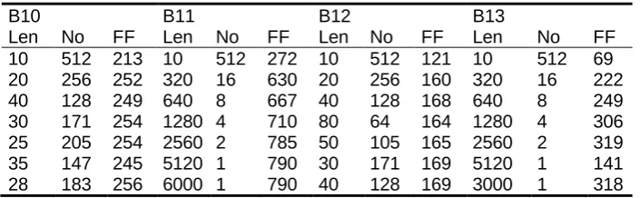
We illustrate the determination of the length of the test subsequence for the benchmarks circuits from ITC’99 suite [15] in Table 3. We chose the initial number of test stimuli equal to 5120. The names of circuits are shown in the first row. Three columns are devoted for each circuit. The first column under Len holds the length of test subsequence; the second column under name No holds the number of subsequences; the third one under name FF holds the number of detected functional delay faults.
It needs to notice that some steps for the circuits’ B11 and B13 are not presented in Table 3. The chosen lengths of test subsequences are shown in bold. Looking at the Table 3, we observe that the circuit B11 requires the longest test subsequence. It is possible to conclude that the determination of the length of the test subsequence for the circuit B11 ran out of the range of the examination. But it is not reasonable to have the longer length, because the number of test stimuli would increase very significantly.
Table 3. Determination of length of test subsequence
B10 B11 B12 B13
Len No FF Len No FF Len No FF Len No FF 10 512 213 10 512 272 10 512 121 10 512 69 20 256 252 320 16 630 20 256 160 320 16 222 40 128 249 640 8 667 40 128 168 640 8 249 30 171 254 1280 4 710 80 64 164 1280 4 306 25 205 254 2560 2 785 50 105 165 2560 2 319 35 147 245 5120 1 790 30 171 169 5120 1 141 28 183 256 6000 1 790 40 128 169 3000 1 318
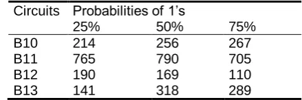
Table 4. Probabilities of 1’s and number of detected functional faults
Circuits Probabilities of 1’s
25% 50% 75%
B10 214 256 267
B11 765 790 705
B12 190 169 110
B13 141 318 289
The sequential circuit usually has control signals that define the mode of functioning. Such signals are reset, start, and clock. There could be some other control signals. The control signals usually have to change according to some law, which is known a priori. Therefore, there is no need to generate values for these signals randomly. The random generation would only hinder to keep the circuit in the functional mode. As the result, the detection of functional delay faults would decline. The sequence of input stimuli, which has defined the values for some inputs only and leaves undefined values for other inputs, is called a test frame [17]. The test frame can be represented as a matrix, where columns correspond to the primary inputs of the circuit and rows are used for the definition of the values in the test subsequence. Some values are defined in the test frame; some values are left undefined. The generation is possible for undefined values only. The test frame is very useful for test generation, because it preserves the defined functioning of the circuit. In our experiments, we have defined the values for reset, start, and clock signals.
When the first three conditions for random test generation, namely, the length of test subsequence, the probability of 1’s, and the test frame are determined, the termination condition of generation has to be defined [18]. The goal of test generation is to detect all the functional delay faults. But some functional delay faults are untestable and their number is unknown. There is no possibility to determine which functional delay faults are untestable. Therefore, some other condition to terminate test generation has to be chosen. Bareisa et al. [18] suggested using as the termination condition a ratio between the serial number of generated input stimuli and the serial number of the last selected stimuli. This ratio should be not less than 3.
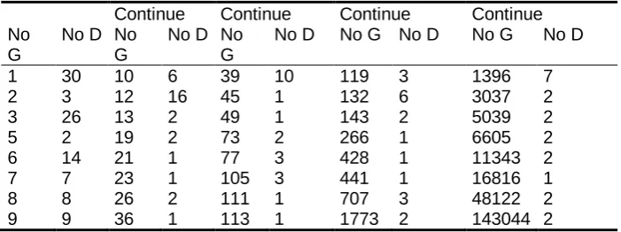
Table 5. Test selection process for circuit B10
Continue Continue Continue Continue No
G
No D No G
No D No G
No D No G No D No G No D
1 30 10 6 39 10 119 3 1396 7
2 3 12 16 45 1 132 6 3037 2
3 26 13 2 49 1 143 2 5039 2
5 2 19 2 73 2 266 1 6605 2
6 14 21 1 77 3 428 1 11343 2
7 7 23 1 105 3 441 1 16816 1
8 8 26 2 111 1 707 3 48122 2
9 9 36 1 113 1 1773 2 143044 2
In the beginning of test generation (Table 5), almost all the generated test subsequences are selected, because there are a lot of undetected functional faults, and every test subsequence usually detects some undetected yet functional delay faults. That is characteristic for all the circuits. When the test generation process proceeds further, the intervals between selection of test subsequences increase. 600000 test subsequences were generated. As we can see the last 450000 test subsequences did not detect new functional delay faults. That is sufficient condition for the termination of test generation process for the circuit B10. But such a condition can be fulfilled for the circuits of small to medium size only. In our experiments, we could fulfill this condition for the circuits from B01 to B13 from ITC’99 benchmark suite only.
The test generation according to the presented process selects always all the generated test subsequences in turn at the beginning of the process. The experimental results provided in Table 5 confirm this observation. But the initially generated test subsequences are not the best ones. This negative feature of test generation process can be easily corrected if to pass the obtained test subsequences through test generation process else one time but in the reverse order. Such a procedure ensures that the number of detected functional delay faults remains the same, but the procedure acts as a test compaction procedure that minimizes the number of test subsequences. For example, we obtained 40 test sequences for the circuit B12. Application of the mentioned procedure enabled to minimize the number of test subsequences to 11 only.
We summarize the acquired experience in functional delay test generation for non-scan sequential circuits into generic approach and provide the pseudocode in 0.
obtained at the gate level by deterministic test generation program TetraMAX.
1: Determine the length of test subsequence
2: Determine the probability of 1’s in test subsequence 3: Determine the test frame for the circuit
4: Generate the functional delay test using the Algorithm (0) until the termination condition is fulfilled or time limit is over
5: Minimize the number of the obtained test subsequences processing them in reverse order
6: The end
Fig.2. Functional delay test generation approach for small to medium size non-scan circuits
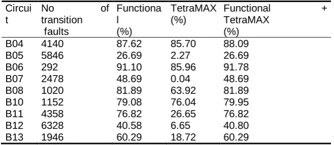
As we can see from Table 6, the functional test performs better than transition test generated at the gate level in all the cases. But the functional test does not detect some transition faults that are detected by the transition fault test, because the combined test obtains higher fault coverage than the tests considered separately. Such a conclusion is valid for the following circuits: B04, B06, B10, and B12.
Looking at the results in Table 6, one may ask why the coverage of transition faults is not high. It needs to notice that the benchmarks are selected in such a way that they have uncontrollable flip-flips, which result into untestable transition faults. It is not possible to prove that the transition fault is untestable using functional test. The same is true for TetraMAX, as well. But the reason is different. TetraMAX cannot prove the untestability of transition faults due to the high complexity of calculations.
Table 6. Coverage of the test subsequences at the gate level Circui
t
No of
transition faults
Functiona l
(%)
TetraMAX (%)
Functional + TetraMAX
(%)
B04 4140 87.62 85.70 88.09
B05 5846 26.69 2.27 26.69
B06 292 91.10 85.96 91.78
B07 2478 48.69 0.04 48.69
B08 1020 81.89 63.92 81.89
B10 1152 79.08 76.04 79.95
B11 4358 76.82 26.65 76.82
B12 6328 40.58 6.65 40.80
B13 1946 60.29 18.72 60.29
calculation time (days) is unacceptable. One of possible solutions is suggested in the next section.
5.
Preliminary Test Selection
The test generation approach presented in Section 4 is based on a fault simulation. The fault simulation is very time-consuming tool. The investigation [9] revealed that simplifications are possible in order to avoid fault simulation in some cases. These simplifications allow achieving considerable time saving without the loss of test coverage. Several simplifications can be made. The general idea of the simplifications is to divide the process of test generation into two following stages: preliminary test selection and test generation based on fault simulation. The goal of the first stage is to minimize the number of test subsequences considered during the second stage. As a consequence, the preliminary selection method has to be a fast method, which enables to remove valueless test subsequences that do not detect the new functional delay faults. Of course, such a method cannot be precise. The approximations should be used. But the approximation should be made to the one direction only; the method should not lose the valuable test subsequences.
We ought to obtain the advantage in the execution time due the following factors: 1) the fault model of the first stage is quite fast; 2) the fault model of the first stage allows rejecting quite a lot of test subsequences. Of course, there is one danger that the fault model of the first stage would allow rejecting the valuable test subsequences.
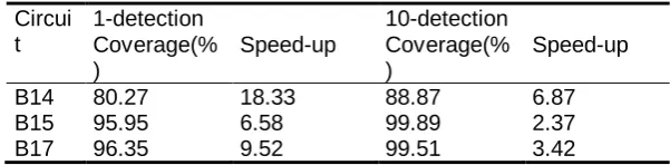
We have investigated two fault models for the first stage. We present them. We have mentioned in the introduction that Kang et al. [6] suggested the TRIO fault model that uses a fault-free simulation only. But they obtained pessimistic results for some circuits. We elaborated their idea further in order to attain better results.
Table 7. TRIO fault model and n-detection Circui
t
1-detection 10-detection Coverage(%
)
Speed-up Coverage(% )
Speed-up
B14 80.27 18.33 88.87 6.87
B15 95.95 6.58 99.89 2.37
B17 96.35 9.52 99.51 3.42
chosen three circuits only as representatives of the large circuits, because the goal of the experiment is to choose the right fault model for the first stage of the test generation.
We generated 10000 random input stimuli for every circuit. We made an assumption that the coverage of functional delay faults is 100% for every circuit in order to easier make comparison among several generations. We selected then test subsequences according to TRIO fault model from initial random input stimuli set using 1-detection and 10-detection. Then we estimated the functional fault coverage of selected test subsequences according to PPFS fault model. The columns under name Speed-up show how many times the test selection according to TRIO fault model and then according to PPFS fault model is faster than the time required to select test subsequences according to single PPFS fault model. For circuit B14 and 1-detection, the considerable improvement in execution time was achieved. But for the same circuit, a quite big loss of fault coverage is observed. Therefore, we can conclude that there is no known a priori value of n-detection. The value of n-detection has to be selected according to the function of circuit.
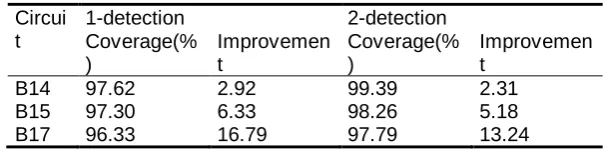
The other proposed preliminary selection method is based on the assumption that the state bits can be considered as the primary outputs. Let us call such a model as combinational PPFS (CPPFS). Selected test subsequences according to the CPPFS fault model do not guarantee the fault effect propagation to the primary output, but their usefulness will be checked during the second stage. The results of experiment similar to the one presented in Table 7 are provided in Table 8. We used n-detection, as well.
We can observe that the selection of test subsequences according to the CPPFS fault model loses lesser number of detected functional delay faults in comparison with TRIO fault model. The other observation is that effectiveness of the CPPFS fault model in conjunction with the second stage increases proportionally to the size of the circuit. The simple explanation exists for the second observation. The increased size of the circuit means the larger number of state bits. The idea of CPPFS fault model is directly related to the state bits.
Table 8. CPPFS and n-detection Circui
t
1-detection 2-detection Coverage(%
)
Improvemen t
Coverage(% )
Improvemen t
B14 97.62 2.92 99.39 2.31
B15 97.30 6.33 98.26 5.18
B17 96.33 16.79 97.79 13.24
presented in 0 in order to apply it for large circuits (0). Step 4 of the approach in 0 is replaced by steps 4-9 in 0.
1: Determine the length of test subsequence
2: Determine the probability of 1’s in test subsequence 3: Determine the test frame for the circuit
4: If the circuit is large, then 5: Use preliminary test selection
6: Generate the functional delay test using the Algorithm (0) on the preselected test set until the termination condition is fulfilled or time limit is over
7: Else
8: Generate the functional delay test using the Algorithm (0) until the termination condition is fulfilled or time limit is over
9: End if;
10: Minimize the number of the obtained test subsequences processing them in the reverse order
Fig. 3. Functional delay test generation approach for non-scan circuits
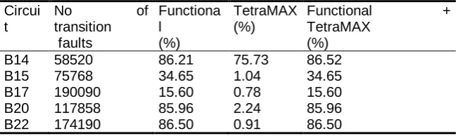
Using the preliminary selection method, we constructed test subsequences for large circuits of ITC’99 benchmark suite (Table 9). It needs to notice that the termination condition defined in Section 4 was not fulfilled due to long generation hours. The test generation time was limited to 24 hours for every circuit.
The format of Table 9 is the same as of Table 6. We provide the comparison with deterministic test generation program TetraMAX. The deterministic test generation program can obtain the comparable fault coverage for smallest circuits only. Complexity of calculations and time restrictions do not allow for TetraMAX to obtain better test calculation results for large circuits.
Table 9. Coverage of test subsequences at the gate level for large circuits Circui
t
No of
transition faults
Functiona l
(%)
TetraMAX (%)
Functional + TetraMAX
(%) B14 58520 86.21 75.73 86.52
B15 75768 34.65 1.04 34.65
B17 190090 15.60 0.78 15.60 B20 117858 85.96 2.24 85.96 B22 174190 86.50 0.91 86.50
6.
Conclusions
We presented functional delay fault test generation approach for non-scan sequential circuits. The circuit is represented as the iterative logic array model, consisting of k copies of the combinational logic of the circuit. The value k defines the number of clock cycles. The approach requires preparation steps for functional delay test generation. The preparation steps encompass the following determination: the length of test subsequence, the probability of 1’s, the test frame, and the number of generation stages. One generation stage is used for smaller circuits. Two generation stages are used for complex and large circuits. During the first stage, which is called preliminary test selection, the simplified fault model is used. The goal of the first stage is to reduce significantly test generation pool by removing invaluable test subsequences. The fault model is simplified that it would be efficient in terms of speed. At the end of generation, the proposed approach uses a simple compaction procedure that enables considerably to minimize the number of generated test subsequences.
The functional delay test generation is based on software prototype model. This model has a great advantage – it is available at the initial stages of the design process. As a consequence, the functional test can be generated before the structural synthesis of the circuit.
The obtained results show that the introduced delay test generation approach outperforms by the fault coverage the transition test stimuli obtained at the gate level by deterministic test generator. The introduced delay test generation approach obtains especially good quality results for the circuits, when the long test subsequences are needed.
References
1. Rearick, J.: Too much Delay Fault Coverage is a Bad Thing. In: Proceedings of the IEEE International Test Conference, 624-633. (2001)
2. Pomeranz, I., Reddy, S.M.: A Delay Fault Model for at-Speed Fault Simulation and Test Generation. In: Proceedings of the IEEE/ACM International Conference on Computer-Aided Design, 89–95. (2006)
3. Pomeranz, I., Reddy, S.M.: Unspecified Transition Faults: A Transition Fault Model for At-speed Fault Simulation and Test Generation. IEEE Transactions on Computer-Aided Design of Integrated Circuits and Systems,Vol. 27, No. 2, 137-146. (2008)
4. Pomeranz, I., Reddy, S.M.: Double-single Stuck-at Faults: A Delay Fault Model for Synchronous Sequential Circuits. IEEE Transactions on Computer-Aided Design of Integrated Circuits and Systems, Vol. 28, No. 3, 426-432. (2009) 5. Rearick, J., Rodgers, R.:Calibrating Clock Stretch During AC Scan Testing. In:
Proceedings of the International Test Conference, 266-273. (2005)
7. Bareiša, E., Jusas, V., Motiejūnas, K., Šeinauskas, R.: Functional Delay Clock Fault Models. Information Technology and Control, Vol. 37, No. 1, 12-18. (2008) 8. Bareiša, E., Jusas, V., Motiejūnas, K., Šeinauskas, R.: Generating Functional Delay Fault Tests for Non-Scan Sequential Circuits. Information Technology and Control, Vol. 39, No 2, 100-107. (2010)
9. Bareisa, E., Jusas, V., Motiejunas, K., Seinauskas, R.: Functional Fault Models for Non-Scan Sequential Circuits, Microelectronics Reliability, Volume 51, Issue 12, 2402-2411. (2011)
10. Hu, X., Song, Z., Wang, J., Geng, Y., Shen, W.: Ant Colony Optimizations for Initalization of Synchronous Sequential Circuits. In: Proceedings of the International Conference on Testing and Diagnosis, 5-18. (2009)
11. Morkūnas, K., Šeinauskas, R.: Circuit Reset Sequences Based on Software Prototypes. Electronics and Electrical Engineering, Vol. 7, No. 103, 71-76. (2010)
12. Pomeranz, I., Parvathala, P.K, Patil, S.: Estimating the Fault Coverage of Functional Test Sequences without Fault Simulation. In: Proceedings of 16th IEEE Asian Test Symposium, 25-30. (2007)
13. Fang, H., Chakrabarty, K., Jas, A., Patil, S., Tirumurti, C.: RT-Level Deviation-Based Grading of Functional Test Sequences. In: Proceedings of 27th IEEE VLSI Test Symposium, 264-269. (2009)
14. Vinutha, K.R., Singh, V., Matrosova, A., Gaur, M.S.: Fault Grading using Instruction-Execution Graph. In: Proceedings of 2010 East-West Design & Test Symposium (EWDTS), 350-357. (2010)
15. Corno, F., Sonza Reorda, M., Squillero, G.: RT-Level ITC'99 Benchmarks and First ATPG Results, IEEE Design and Test of Computers, Vol. 17, No. 3, 44-53. (2000)
16. Bareiša, E., Bieliauskas, P., Jusas, V., Targamadzė, A., Motiejūnas, L., Šeinauskas, R.: Factor of Randomness in Functional Delay Test Generation for Full Scan Circuits. Electronics and Electrical Engineering. Vol. 9, No. 105, 39– 42. (2010)
17. Bareisa, E., Jusas, V., Motiejunas, K., Seinauskas, R.: Functional Test Generation Remote Tool. In: Proceedings of the 8th Euromicro Conference on Digital System Design (DSD'2005), 192-195. (2005)
18. Bareiša, E., Jusas, V., Motiejūnas, K., Šeinauskas, R.: Functional Test Generation Based on Combined Random and Deterministic Search Methods. Informatica, Vol. 18, No. 1, 3-26. (2007)
Eduardas Bareisa graduated from Kaunas Polytechnic Institute (Lthuania) in 1975. He received the D.Sc. degree from Kaunas Polytechnic Institute in 1987. Since 2005, he is professor at Department of Software, Kaunas University of Technology, Lithuania. He is author and co-author of more than 70 papers. His research interests include high-level synthesis, VLSI test generation, and software testing.
research interests include testing of VLSI circuits, design for testability, and design verification
Kestutis Motiejunas graduated from Dresden University of Technology in 1973 (Germany). He received the D.Sc. degree from Kaunas Polytechnic Institute in 1981 (Lithuania). Since 2006, he is professor at Department of Software, Kaunas University of Technology, Lithuania. He is author and co-author of more than 70 papers. His research interest include testing of VLSI circuits, design for testability, and design verification.
Rimantas Seinauskas graduated from Kaunas Polytechnic Institute (Lithuania) in 1968. He received the D.Sc. degree from Kaunas Polytechnic Institute in 1972 (Lithuania), and the Habil. D.Sc. degree from St.Petersburg Institute of Fine Mechanics and Optics (Russia) in 1982. Since 1985, he is professor at Department of Software, Kaunas University of Technology, Lithuania. He is author and co-author of more than 100 papers. He is Editor-in-Chief of journal “Information Technology and Control”. His research interest include testing of VLSI circuits, design for testability, and design verification