Eight-Element Antenna Array at 3.5 GHz for MIMO
Wireless Application
Mujeeb Abdullah*, Yong-Ling Ban, Kai Kang, Ming-Yang Li, and Muhammad Amin
Abstract—A multiple-input-multiple-output (MIMO) antenna array with eight printed coplanar waveguide (CPW)-fed monopole antennas operating at 3.5 GHz (3.4–3.6 GHz) is presented. Each antenna is an Inverted-L (IL) monopole surrounded by a parasitic IL-shorted stripe and attains compact configuration. Both the IL-monopole and parasitic IL-shorted stripe contribute their fundamental resonant modes to operate in the desired frequency band. The neutralization line (NL) and ground middle slot are used for decoupling the antenna elements in the array. The measurement results for the prototype reasonably agree with electromagnetic simulations. Measured results for the proposed MIMO antenna array demonstrate that it has impedance bandwidth more than 200 MHz with (S11<6 dB), and
with effective antenna decoupling mechanism, the mutual coupling is better than 10 dB for the required band (3.4–3.6 GHz). Also, envelope correlation coefficient (ECC) for the proposed MIMO antenna array is less than 0.2 for any two antennas to realize independent prorogation path for a channel. The average channel capacity of the proposed MIMO antenna array is approximately 35 to 38 bps/Hz for a reference signal to noise ratio (SNR) of 20 dB.
1. INTRODUCTION
The next generation communication systems (5G) will implement multiple-input-multiple-output (MIMO) technology to comply with the increasing demands on greater spectrum efficiency, maximum throughput, and short latency. It employs numerous antennas at the transceiver end, to utilize multi-path channels for maximum data rate [1]. To accommodate multiple antennas, the mutual coupling between antenna elements is a major limiting factor. The mutual coupling exists between the antenna elements is due to near-field coupling and the common ground plane for the current. The mutual coupling can reduce the antenna efficiency and deteriorate the radiation pattern. Hence, one of the core challenges of employing MIMO antenna array in a smartphone is to accommodate multiple antennas with low mutual coupling [2]. Recently, many MIMO antenna arrays have been proposed for the use in mobile terminals. In [3], a single antenna element (Inverted-F/Slot) is printed at each of the four corner edges of circuit board operates for HiperLAN in the 5 GHz band and 2.4 GHz ISM band. In [4], a four-antenna array operating in LTE700/2300/2500 GSM900/1800/1900 and WLAN 2.4 GHz band is presented. The four antenna elements in [5] consist of the main antenna printed on a small non-ground space of 65×9.5 mm2, and three auxiliary antennas are placed perpendicular to the printed circuit board resulting in a low mutual coupling. However, the aforementioned antenna structures in [3– 7] accommodating only four antenna elements at maximum with operating frequency bands only for LTE/GSM/UMTS and WLAN restrict their application for 5G mobile broadband services at 3.5 GHz. As few structures with multiple antennas more than four elements is reported [8] for 2.6 GHz and in [9] for 2.4 GHz. In [10], the multiple antenna elements array is obtained by accommodating decoupled printed
Received 23 August 2017, Accepted 29 September 2017, Scheduled 17 October 2017
* Corresponding author: Mujeeb Abdullah ([email protected]).
2. ANTENNA DESIGN
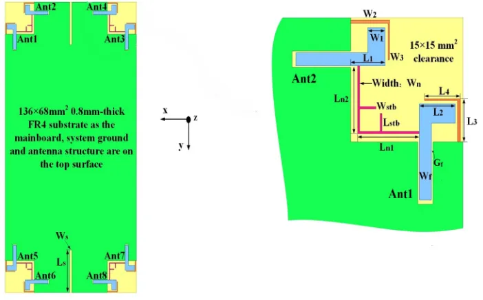
The geometry of the proposed eight-element antenna array (MIMO antenna array) with decoupling network (neutralization line and ground middle slot) is presented in Fig. 1 and the fabricated structure in Fig. 2. The eight-antenna array and ground plane are printed on the top side of an FR-4 substrate with thickness of 0.8 mm as main board. The size of the main board is 136×68 mm2, (1.61λo×0.74λo, λo represents the free space wavelength at 3.5 GHz). Furthermore, the eight antennas of the array are divided into four pairs. Each pair has two IL-monopoles with same dimensions, and orthogonal configuration is designed in the clearance area (non-ground layout) of 15×15 mm2 (0.17λo ×0.17λo) at the four corner edges of the main board. A CPW-fed structure with Wf = 1.64 and gap distance of Gf = 0.2 is used for feeding each antenna. The parasitic IL-shorted stripe is placed in nearby vicinity of each monopole antenna resemble square loop with path length (L1 to L2) and (L3 to L4) of
approximately 17.6 mm close to a quarter-wavelength at 3.5 GHz. Therefore, each monopole antenna resonates at 3.5 GHz. The decoupling structure, consisting of neutralization line (NL) and ground slot is inscribed in the middle top edges of ground plane. The prefixLis used to denote length, and likewise, W denotes the width in the geometric description. The optimized dimensions are as follows (Unit:mm): L1 = 4.6, L2 = 3.2, L3 = 5, L4 = 4.8, Ln1 = 8.25, Ln2 = 7.94, Wn = 0.26, Ws = 0.6, Ls = 20,
W2 = 0.4, W3 = 0.2,Lstb = 2.2, Wstb = 0.25, Wf = 1.6 andGf = 0.2. The electromagnetic simulator
CST Microwave Studio is used to simulate and optimize the proposed MIMO antenna array.
Figure 2. Photograph of the fabricated structure of the MIMO antenna array.
(a) (b)
(c) (d)
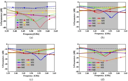
Figure 3. Simulated S-parameters for MIMO antenna array. (a) Without decoupling network. (b) With neutralization line as decoupling network. (c) With neutralization line as decoupling network and stubs (for tuning). (d) With neutralization line and ground middle slot) as decoupling network and stubs (for tuning).
Considering the symmetry of the proposed structure, the performances of two antennas (Ant1 and Ant2) are discussed. For clarity, the return losses of Ant1 and Ant2 and S-parameters to quantify mutual coupling among antennas as illustrated by (Sij (i, j= 1,2,3,4; i=j)) are presented in Fig. 3.
3. ISOLATION AND DECOUPLING TECHNIQUE ANALYSIS
Without using any isolation network, the mutual coupling between Ant1 and Ant2 yields a maximum value of (S21 = −9.8 dB) as illustrated in Fig. 3(a). The mutual coupling between two orthogonal
Lstb Wstb
(3.4–3.6 GHz) as demonstrated in Fig. 3(c). As NL is placed near the ground plane, exciting surface waves yields unwanted (S31 = −10 dB). As suggested in [15], ground defect structure has been used
to prevent surface wave propagation on the ground plane. A rectangular slot with a length of Ls and width of Ws is engraved in the centric position (top edge system ground plane) to impede current flow from Ant1 to Ant3 resulting inS31=−17 dB as presented in Fig. 3(d).
4. SIMULATED SURFACE CURRENT DISTRIBUTION
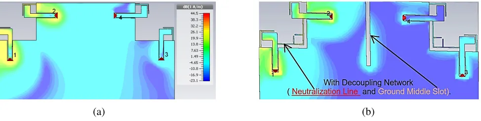
The decoupling mechanism (NL and ground slot) can be best understood by studying the surface current distribution at 3.5 GHz as plotted in Fig. 4(a). Port 1 is excited, and corresponding other ports are terminated in 50 Ω. In Fig. 4(b), it is demonstrated that by using antenna decoupling methods, namely NL and ground defect structure (Ground Middle slot), mutual coupling is reduced. The new coupling current on the NL compensates the original coupling current, resulting in the weakening of mutual coupling between Ant1 and Ant2. Moreover, the rectangular slot loaded ground plane traps a large amount of current flow from Ant1 to Ant3 due to surface excitation by NL, and it also impedes the current flow between Ant2 and Ant4. Thus antenna decoupling mechanism improves isolation among antenna elements (Ant1 to Ant4).
(a) (b)
Figure 4. Simulated current distribution at 3.5 GHz. (a) Without antenna decoupling techniques. (b) With antenna decoupling techniques.
5. RESULTS AND DISCUSSION
As illustrated in Fig. 1, the proposed MIMO antenna array (an eight-antenna array) is fabricated to validate the numerical results computed by CST microwave studio. The S-parameters are measured using an Agilent N5247A vector network analyzer. And the measurement of far-field radiation is carried out in a SATIMO microwave anechoic chamber at 3.5 GHz.
3.35 3.40 3.45 3.50 3.55 3.60 3.65 0
13 26 39 52 65
Proposed 8-antenna arra y
5.75 bps/Hz, upper link for SIS O
Channel capacity [bps/Hz]
Frequency [GHz] 46 bps/Hz upper limit for 8×8
(a) (b)
(c) (d)
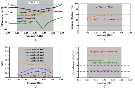
Figure 5. Measured results for MIMO antenna array. (a) S-parameters. (b) Antenna efficiency. (c) Envelope correlation coefficient. (d) MIMO channel capacity.
supports the decoupling of the antenna structures of the top edge (Ant1 to Ant4) and bottom edge (Ant5 to Ant8). Therefore, the S-parameters from (Ant5 to Ant8) are not discussed. The decoupling configuration is found to exhibit good isolation among antennas, greater than 10 dB for (3.4–3.6 GHz) as shown in Fig. 5(a). Moreover, the measured antenna efficiency considering reflection losses and radiation efficiency of Ant1 varies between 40 and 50%. Similarly, for Ant2 the antenna efficiency ranged between 50 and 60% (which is acceptable) owing to middle ground slot resonant behavior and improvement in impedance matching as presented in Fig. 5(b).
The ECC and MEG are calculated according to the assumptions stated in [16, 17]. The ECC is calculated from the measured 3-D far-field radiation pattern obtained using a SATIMO microwave anechoic chamber. From Fig. 5(c), it can be seen that the ECC values are less than 0.2 for any combination of two antennas of the array in the required band of operation. Thus, it meets the required standard of ECC less than 0.5 for acceptable diversity gain required by communication system. The ergodic channel capacity for MIMO antenna array in the desired band (3.4–3.6 GHz) varies from 35 to 38 bps/Hz as illustrated in Fig. 5(d).
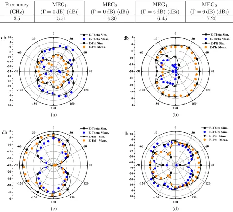
The mean effective gain is important performance metric for MIMO communication array as it quantifies the interaction between antenna and communication channel. Based on a series of assumptions for mobile propagation environment stated in [17], the MEG can be formulated as follows:
MEG = 1
2π
2π
0
Γ Γ + 1Gθ
π
2, ϕ
+ Γ
Γ + 1Gϕ
π
2, ϕ
dϕ (1)
-25 -20 -15 -10 -150 -120 -90 90 120 150 180 -25 -20 -15 -10 -5 0 5 10 -20 -15 -10 -150 -120 -90 90 120 150 180 -20 -15 -10 -5 0 5 -25 -20 -15 -10 -5 0 -150 -120 -90 -60 -30 0 30 60 90 120 150 180 -25 -20 -15 -10 -5 0 E-Theta Sim. E-Theta Meas. E-Phi Sim. E-Phi Meas. db -40 -30 -20 -10 0 10 -150 -120 -90 -60 -30 0 30 60 90 120 150 180 -40 -30 -20 -10 0 10 E-Theta Sim. E-Theta Sim. E-Phi Sim. E-Phi Meas. db (a) (b) (c) (d)
Figure 6. Simulated (sim.) and measured (meas.) radiation pattern for the proposed MIMO antenna array at 3.5 GHz. (a) Ant1 XZ-plane. (b) Ant1 Y Z-plane. (c) Ant2 XZ-plane. (d) Ant2 Y Z-plane.
6. CONCLUSION
An eight-antenna array is proposed for future wireless communication systems operating at 3.5 GHz for mobile broadband services. Measured results are in fair agreement with simulated ones obtained from CST Microwave Studio. Each antenna operates in the desired frequency band of operation (3.4– 3.6 GHz) with minimum acceptable isolation greater than 10 dB. The ECC of less than 0.2 is achieved for any two antennas in the proposed MIMO antenna array. Also, the MEG ratio of Ant1 and Ant2 as representative of the proposed MIMO antenna array meets the required standard of unity. The calculated ergodic channel capacity is approximately 35 to 38 bp/Hz with 20 dB as reference SNR. It is seven times larger than ideal SISO systems capacity of 5.7 bps/Hz.
ACKNOWLEDGMENT
This research was financially supported by the National Natural Science Foundation of China by a grant (No. 61471098).
REFERENCES
1. Zheng, L. and D. N. C. Tse, “Diversity and multiplexing: A fundamental tradeoff in multiple-antenna channels,” IEEE Trans. Info. Theo., Vol. 49, No. 5, 1073–1096, 2003.
2. Sharawi, M. S., “Current misuses and future prospects for printed multiple-input, multiple-output antenna systems,” IEEE Antennas and Propagation Magazine, Vol. 59, No. 2, 162–170, 2017. 3. Liao, W. J., C. Y. Hsieh, B. Y. Dai, and B. R. Hsiao, “Inverted-F/slot integrated dual-band
four-antenna system for WLAN access points,”IEEE Antennas Wireless Propag. Lett., Vol. 14, 847–850, 2015.
4. Guo, J., J. Fan, L. Sun, and B. Sun, “A four-antenna system with high isolation for mobile phones,”
IEEE Antennas and Wireless Propag. Lett., Vol. 12, 979–982, 2013.
5. Yang, L., H. Xu, J. Fang, and T. Li, “Four-element dual-band MIMO antenna system for mobile phones,”Progress In Electromagnetics Research C, Vol. 60, 47–56, 2015.
6. Wong, K.-L., Y.-C. Chen, and W.-Y. Li, “Four LTE low-band smartphone antennas and their MIMO performance with user’s hand presence,” Microw. Opt. Technol. Lett., Vol. 58, 2046–2052, 2016.
7. Ramachandran, A., S. Valiyaveettil Pushpakaran, M. Pezholil, and V. Kesavath, “A four-port MIMO antenna using concentric square-ring patches loaded with CSRR for high isolation,” IEEE Antennas and Wireless Propag. Lett., Vol. 15, 1196–1199, 2016.
8. Li, M. Y., Y. L. Ban, Z. Q. Xu, G. Wu, C. Y. D. Sim, K. Kang, and Z. F. Yu, “Eight-port orthogonally dual-polarized antenna array for 5G smartphone applications,” IEEE Transactions on Antennas and Propagation, Vol. 64, No. 9, 3820–3830, 2016.
9. Choi, I. D., K. Lee, and J. Y. Lee, “A miniaturized 8-port integrated antenna with low farfield pattern correlation,” IEEE International Symposium on Antennas and Propagation (APSURSI), 911–912, 2016.
10. Wong, K.-L., J.-Y. Lu, L.-Y. Chen, W.-Y. Li, and Y.-L. Ban, “8-antenna and 16-antenna arrays using the quad-antenna linear array as a building block for the 3.5-GHz LTE MIMO operation in the smartphone,”Microw. Opt. Technol. Lett., Vol. 58, No. 1, 174–181, 2016.
11. Harrysson, F., J. Medbo, A. F. Molisch, A. J. Johansson, and F. Tufvesson, “Efficient experimental evaluation of a MIMO handset with user influence,” IEEE Transactions on Wireless Communications, Vol. 9, No. 2, 853–863, 2010.
12. Mao, C. X., Q. X. Chu, et al., “Compact coradiator UWB-MIMO antenna with dual polarization,”
IEEE Transactions on Antennas and Propagation, Vol. 62, No. 9, 4474–4480, 2014.
Antennas and Propagation, Vol. 56, No. 11, 3552–3565, 2008.
18. Ding, Y., Z. Du, K. Gong, Z. Feng, et al., “A four-element antenna system for mobile phones,”