Analysis of loop heat pipe performance under varying wick load
A. Heitor Reis
1,2, António F. Miguel
1,2and Murat Aydin
2,31Physics Department, University of Évora, R. Romão Ramalho, 59, 7000-671 Évora, Portugal 2Évora Geophysics Center, R. Romão Ramalho, 59, 7000-671 Évora, Portugal 3Dep. of Mech. Engineering, Istanbul Technical University, 34439 Gumussuyu, Istanbul, Turkey
e-mail:[email protected]
Abstract
Loop heat pipes (LHP) are heat transfer devices used to enhance cooling of small spaces and basically consist of sealed tubes connecting a heat source, the evaporator, whose major part is a porous wick, with a condenser that operates as heat sink. In this paper we analyse the effect of curvature of the liquid vapor interface upon the vapor pressure within wick pores. We show how this effect affects start-up by requiring a difference between wick and condenser temperatures as higher as wick pore width becomes smaller. We analysed also transient operation and found that idealy LHP are self-adjusting systems that tend to stable operation. We present a formula to describe the transient regime. The analysis provides also optimization of wick pore width for maximum heat transfer. Optimal pore width is shown to vary with temperature difference between wick and condenser. It is envisaged how this feature may help in LHP design.
Introduction
Loop heat pipes (LHP) are heat transfer devices in which a working fluid transfers continuously heat from the evaporator to the condenser. LHP operate under a pressure difference generated at a porous wick (the evaporator) and that drives the working fluid within the loop (see Fig.1). The pressure difference is due to the capillary forces drives the liquid from the condenser into the evaporator while the difference between the saturation pressures corresponding to the evaporator and condenser temperatures drive the vapor back into the condenser.
LHP have been broadly used in electronics cooling, spacecraft and other areas. Numerous papers dealing with various aspects of LHP performance characteristics have been published so far [1-12]. Our purpose is not to review this abundant literature extensively but just to focus on a feature whose complete comprehension remains rather elusive: LHP require a pressure difference across the wick in order to start properly. This is usually overcome through the use of active devices to assist in the start-up. Although some structural aspects of LHP may contribute to start-up problems, we believe that thermodynamics play here the major role.
When analyzing LHP cycles it is commonly assumed that wick pressure follows Clausius-Clapeyron equation that relates pressure to temperature at an equilibrium
planar liquid-vapor interface. However liquid-vapor interfaces in the wick pores are far from being planar. In fact such interfaces are in a shape of meniscus which implies that the equilibrium vapor pressure P follows Kelvin’s equation [13,14]:
¸¸ ¹ · ¨¨
© §
U T J
T R d
cos 4 exp
PPs L g (1)
where Ps is the saturation pressure corresponding to a planar interface, J is surface tension, T is solid/liquid contact angle, d is pore width, UL is density of liquid, Rg is the specific gas constant and T is temperature. Eq. (1) indicates that liquid can boil in the wick pores even if pressure in the overlying vapor is well bellow the saturation pressure corresponding to a planar interface that is given by Clausius-Clapeyron equation:
» ¼ º «
¬ ª
¸ ¹ · ¨
©
§
0 g
LV 0
s
T 1 T 1 R h exp P
P (2)
where hLV stands for the enthalpy of evaporation and the subscript 0 for reference values.
d*= (ULhLV/JcosT)d , and combining Eqs. (1) and (2) we obtain:
» » ¼ º
« « ¬ ª
¸¸ ¹ · ¨¨ © §
*
0 0
T 1 d
4 1 T
1 exp P
P (3)
For difference in temperature such that 'T*/T*<<1, the vapor pressure difference between two successive menisci D and E (see Fig. 2 and [13] for details) is:
¸ ¸ ¹ · ¨ ¨ © §
¸ ¸
¹ · ¨ ¨
© §
|
D D E E E D
d 4 1 T
1 d
4 1 T
1 P
P P
(4)
where <P> represents the average pressure of the vapor between the menisci.
Fig. 1. Schematic representation of a LHP (major parts).
When d*of (planar interface) Eq. (3) reduces to Clausius-Clapeyron equation. However, when d* is finite the vapor pressure is lower than saturation pressure at the same temperature. This effect is as much important as the pore width becomes smaller. As a consequence when both the evaporator and condenser are at the same temperature T*, vapor pressure in the wick is lower than that in the condenser (see Eq. (4) and [13] for details):
0 d
1 D
1 T
4 P
P P
C C
W
¸ ¸ ¹ · ¨
¨ © §
|
(5)
where
D
C>>d* are the curvature radiuses of the liquid-vapor interfaces in the condenser and the wick, respectively. To start LHPs one has to surpass this negative pressure difference by increasing the wick temperature. By using Eq. (4) again, we see that LHP start-up can only occur for values of the ratio of wick temperature to condenser temperature higher than:* C
W
d4 1 T T
|
(6)
This is one of the reasons why LPHs require a significant
Fig. 2. Liquid/vapor interfaces of different curvature radiuses. Pressure and temperature of the vapor in equilibrium with the liquid depends upon the radius of curvature of the interface.
Nomenclature
D – duct diameter (m) U – density (kg m-3
d – pore width (m) T – solid/liquid contact angle (rad) hLV – enthalpy of evaporation (J kg-1)
L – duct lenght (m) Superscript
m – mass flow rate (kg s-1) * – non-dimensional
n – number of wick pores
P – pressure (Pa) Subscripts
Ps – saturation pressure (Pa) C – condenser
Q – heat current (W s-1) eq – equilibrium
Rg – specific gas constant (J kg-1 K-1) L – liquid
T – temperature (K) max – maximum value
t – time (s) op – optimal
I – wick load (liquid) V – vapor
J – surface tension (N m-1) W – wick
Q – kinematic viscosity (m2 s-1) 0 – reference value
vapor liquid liquid
T
P
*D
D
T P
*E E
d
*D
d
*
E
Evaporator
Vapor grooves
Condenser
Vapor line Primary wick Secondary wick
Liquid line Compensation
chamber
difference of wick to condenser temperature in order to start properly. Otherwise LHPs can even start with vapor condensation in the wick, which is recognized as “the ability to occasionally start in the reverse direction” [12].
Authors of recent LHP literature [1-12] do not consider the effect of the curvature of the interface upon the vapor pressure and usually restrict the explanations of start-up difficulties to features of LHP operation.
In this paper we address the problem LHP operation under varying heat load by taking into account the effect of interface curvature upon pressure of the vapor in the wick.
Analysis of transient LHP operation
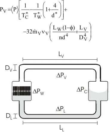
The sum of the pressure heads and drops along a closed path within a LHP must be zero. Therefore for a LHP in a horizontal plane if 'PW, 'PV, 'PC and 'PL denote the pressure differences across the liquid-vapor interface at the wick, between vapor at the condenser and the wick, across the liquid-vapor interface at the condenser and between liquid in the wick and the condenser, respectively (see Fig. 3), this condition reads:
'PW+'PV + 'PC + 'PL=0 (7)
The pressure difference across the liquid-vapor interface in the wick is given by the Young-Laplace equation as [13]:
d cos 4
PW J T
' (8)
The vapor pressure difference between condenser and wick is the sum of the pressure head given by Eq. (4) with the pressure drop due to vapor flow (see Fig. 3):
» » ¼ º
« « ¬ ª
¸¸ ¹ · ¨¨ © §
'
d
4 1 T
1 T
1 P P
W C V
¸ ¸ ¹ · ¨
¨ © §
I Q
4
V V 4 W V V
D L nd
) 1 ( L m
32 (9)
Fig. 3. Schematic representation of the liquid and vapor phases within the LHP as well as pressure differences and diameter and length of the liquid and vapor lines.
Fig.4 Schematic representation of the liquid vapor interface in the wick. Wick load is represented by I that is the wick’s pore filling level.
In Eq. (9) both dimensional and dimensionless variables coexist as an intermediary step towards a final dimensionless equation to be presented further on. Also in Eq. (9) mVis vapor flow rate, d and d* are pore width and dimensionless pore width, n is the number of wick’s pores and the subscripts C, V, W represent condenser, vapor and wick.
We assume planar liquid-vapor interface in the condenser and therefore
'PC= 0 (10)
By assuming Hagen-Poiseuille flow along the liquid line, the pressure drop is given by:
¸ ¸ ¹ · ¨
¨ © §
I Q
' 4
L L 4 W L L L
D L nd L m 32
P (11)
where mLis liquid flow rate and the subscript L stands for liquid.
In the wick, heat (Q)is absorbed almost totally by the liquid phase (see Fig. 4) therefore we assume that
0 Q
Q I (12)
where Q0represents the heat current absorbed by the wick at maximum load (I=1).
We define wick’s varying load Ias:
W 2 L
V L
L d n
m m
U
I (13)
By combining Eqs. (7)-(13) and adding to the already defined d* and T* the following dimensionless variables:
- P* P/(ULhLV)
- t* t(Q /(nULd2LWhLV)
- Q* Q
32 L /( Ld2LWh2 )LV U
Q 'PL
'PW 'PC
'PV
LV
LL
DV
DL
Liquid
Vapor
q
VaporL
Wd
I
we arrive at the following equation: » » ¼ º « « ¬ ª ¸¸ ¹ · ¨¨ © § * * W * C * * d 4 1 T 1 T 1 P d 4 » » » ¼ º « « « ¬ ª ¸ ¸ ¹ · ¨ ¨ © § I I *4 L 2 * * L * W 2 * * W * 0 * D d L nL d L Q 0 D L n D nL ) 1 ( d L L d
Q *4
V L * V V 4 * L * L L V 4 * * W * W 2 * * 0 » » ¼ º « « ¬ ª Q Q ¸¸ ¹ · ¨¨ © § I Q Q I I (14) In Eq. (14) the first and second terms represent liquid and vapor pumping heads, respectively while the remaining terms represent pressure drops due to fluid flow. Since D*V;D*V!!d*and QVQL Eq. (14) can be
simplified to:
0
H*I*II2 (15)
where °¿ ° ¾ ½ °¯ ° ® » » ¼ º « « ¬ ª ¸¸ ¹ · ¨¨ © § ¸ ¸ ¹ · ¨ ¨ © § * * W * C * * 2 * W * * 0 * d 4 1 T 1 T 1 P d 4 L d Q 1 H (16)
is the dimensionless total pumping head. The general solution of Eq. (15) is
) t 2 exp( A
H*I2 * (17)
where A is a constant to be determined from initial conditions. At t*= 0, H 2 A
0
*I and when t*o f, the dimensionless pumping head equals equilibrium wick load, i.e.
2 eq *
H I (18)
which implies that for reaching stable (equilibrium) operation the total pumping head H* cannot be negative. This equilibrium condition also follows from Eq. (17) with I* 0that corresponds to liquid flow rate being equal to vapor flow rate. Therefore rearranging Eq. (17) one obtains: ) t 2 exp( * 0 2 eq 2 2 eq I I I I (19)
which by taking into account Eq. (12) and the definitions of Q*and t* may be also expressed in terms of the heat current absorbed at the wick as
¸ ¹ · ¨ © § U t h L d n Q 2 exp Q Q Q Q LV W 2 0 0 2 eq 2 2 eq (20)
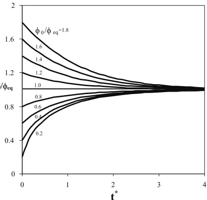
Fig. 5. Variation of wick load with time. Lines correspond to different ratios of start-up loads to equilibrium wick load. Stable operation may be reached by starting either from above or from bellow equilibrium load (I 0)that matches stable operation.
The variation of wick load I, with time is shown in Fig. 5. We see that stable operation (equilibrium) may be (ideally) reached either from above or from bellow the equilibrium wick load. In practice, often the wick is not in equilibrium itself what may lead to additional troubles in LHP operation [12]. However as Fig. 5 shows, LHPs have a self-adjusting capacity that enable them to reach stable operation.
As H* Ieq2 >0,(see Eq. 18) the total pumping head has to be always positive in order LHP to start and keep on functioning. From Eq. (16) this implies that start-up must comply with the following inequality:
4 / d P / T 4 / d 1 T
T * * *
C * C W !
! (21)
For a planar surface, as d*o f the start-up condition would be TW>TC simply.
By considering the definitions of T* and P* we conclude that TC*/P*! is of order UV/UL|103 what enables us to consider that the general condition expressed by Eq. (21) is not impeditive of LHP functioning. Although Eq. (21) is a necessary condition for LHP start-up it does not represent a sufficient condition. In fact, by Eq. (16) H* is the sum of the liquid and the vapor pumping head. Since the first, 4/d*, is always positive the second one may be negative. Nevertheless it is sufficient for LHP start-up that wick and condenser temperatures additionally comply also with Eq. (6). From Eq. (6) we conclude that curvature effects of the wick’s liquid-vapor interface become important for d*= (ULhLV/JcosT)d smaller than 103 (see Eq. 6). Since (ULhLV/JcosT) | 1010 m-1 significant difference between wick and condenser temperatures is
t*ttt 0 0.4 0.8 1.2 1.6 2
0 1 2 3 4
IIeq
required to start LHPs with wick pore widths smaller than 0.1Pm.
Optimization of wick’s pore width for LHP design
The analysis of the preceding section may become useful in LHP design as it allows for the optimization of wick pore width. By combining Eqs. (12) and (18) one obtains:
2 / 1
* * W * C * * * 0 *
* * eq
d 4 1 T
1 T
1 P d
4 Q L
d Q
W »
»
¼ º
« «
¬ ª
¸ ¸
¹ · ¨
¨
© §
¸ ¸ ¹ · ¨
¨ © §
¸¸ ¹ · ¨¨ © §
(22)
By analyzing Eq. (22) we can see that heat absorbed at stable operation Q*eq, can be maximized with respect to wick’s pore diameter d*. The optimal pore diameter is a function of wick and condenser temperatures of the form:
* C * W
* W *
* C * * C *op
T T
T T
T P T 2 d
W ¸
¸ ¹ · ¨
¨ © §
(23)
which in dimensional form reads:
C W
W C
C g L
LV L op
T T
T T
T P
T R h
cos 2 d
W ¸
¸ ¸
¹ ·
¨ ¨ ¨
© §
U
U T
J (24)
Eq. (24) shows that wick pore diameter that allows for maximum heat transfer is as smaller as the difference between wick and condenser temperatures gets higher. On the other end we see that dopof (planar surface) as TWoTC.
In Eq. (24) the term within brackets is of order 3
L V/U |10
U while (2JcosT/ULhLV)| 10-10 m-1. Therefore for TW –TC|10 K and T | 300K, dop is of order 3Pm.
Therefore Eq. (24) may help LHP manufacturers in choosing the wick pore diameter that matches optimal performance at prescribed wick and condenser temperatures.
Conclusions
The analysis of loop heat pipe (LHP) carried out in this paper shows that curved liquid vapor interfaces may change significantly equilibrium vapor pressure in wick pores of widths of order 1 Pm. and smaller. This affects LHP start-up by requiring significant difference between wick and condenser temperatures for start-up to occur. This difference in temperature gets higher as the wick pore width becomes smaller.
Solution of a differential equation describing transient functioning shows that LHP are self-adjusting systems that ideally tend to stable operation either if started from
above or from below stable operation points. However LHP start-up from below stable operation points are unlikely to occur in LHP whose wick pores are of order 1 Pm and smaller due to the above mentioned difference between wick and condenser temperatures required to start-up.
Optimization of performance of LHP with respect to wick pore width shows that optimal pore width can be related to wick and condenser temperatures and vary linearly with the Carnot coefficient of performance of heat pumps. This aspect may help in choosing the appropriate wick structure for prescribed LHP operating conditions.
References
1. Ku, J. Operating characteristics of loop heat pipes, Proc. 29th Int. Conf. Of Environ. Systems, paper No. 981212,
(1999) Denver, USA.
2. Kamotani, Y,Thermocapillary flow under microgravity – Experimental results, Adv. Space Res. 24, 10 (1999). 1357-1366.
3. T. Kaya and T. Hoang, Mathematical modeling of loop heat pipes and experimental validation, J. of Thermophysics and Heat Transfer 13, 3, (1999) 314-320. 4. I. Muraoka, F. M. Ramos, V. V. Vlassov, Analysis of the
operational characteristics and limits of a loop heat pipe with porous element in the condenser, Int. J. of Heat and Mass Transfer 25, 8 (2001) 2287-2297.
5. R. Chandratilleke., H. Hatakeyama, and H. Nakagome, Development of cryogenic loop heat pipes, Cryogenics 38, (1998) 263-269.
6. N. Zhang, Innovative heat pipe systems using a new working fluid. Int. Comm. Heat Mass Transfer, 28 (2001) 1025-1033.
7. H. F. Smirnov and B. V. Kosoy, Refrigerating heat pipes, Appl. Therm. Eng. 21 (2001) 631-641.
8. Q. Liao. and T. S. Zhao, Evaporative heat transfer in a capillary structure heated by a grooved block, J. of Thermophysics and Heat Transfer 13,No.1 (1999) 126-133.
9. J. S. Allen, K .P.Hallinan and J. Lekan, A study of the fundamental operations of a capillary driven heat transfer device in both normal and low gravity, AIP Conference Proceedings 420, (1998) 471-477, Ed. American Institute of Physics, Woodbury, New York.
10. C. Figus, Y. Le Bray, S. Bories, and M. Prat Heat and mass transfer with phase change in a porous structure partially heated: continuum model and pore network simulations, Int. J. of Heat and Mass Transfer 42 (1999) 2557-2569.
11. J. Ku, Operating characteristics of loop heat pipes, Int. Conf. on Env. Syst., paper 1999-01-2007.
12. J. Baumann, B. Cullimore; J. Ambrose, E. Buchan and B. Yendler, A methodology for enveloping reliable start-up pf LHPs. Paper nº 2000-2285, (2000) Am. Inst. of Aeronautics and Astronautics, Inc.
13. A. H. Reis, Thermodynamics of fluids in mesoporous media, in D. B. Ingham (Ed.) Proc. of NATO Adv. St. Inst. on Porous Media, 9-20 June 2003, Ovidius Un. Press (2003).