Burst-by-Burst Adaptive Turbo-Coded Radial Basis
Function-Assisted Decision Feedback Equalization
M. S. Yee, Associate Member, IEEE, T. H. Liew, and Lajos Hanzo, Senior Member, IEEE
Abstract—The performance of the proposed radial basis func-tion (RBF) assisted turbo-coded adaptive modulafunc-tion scheme is characterized in a wideband channel scenario. We commence by introducing the novel concept of the Jacobian RBF equalizer, which is a reduced-complexity version of the conventional RBF equalizer. Specifically, the Jacobian logarithmic RBF equalizer generates its output in the logarithmic domain and hence it can be used to pro-vide soft outputs for the turbo-channel decoder. We propose using the average magnitude of the log-likelihood ratio (LLR) of the bits in the received transmission burst before channel decoding as the channel quality measure for controlling the mode-switching regime of our adaptive scheme.
Index Terms—Adaptive modulation, AQAM, decision feedback equalizer, DFE, Jacobian logarithm, neural network, radial basis function, RBF, turbo coding.
I. BACKGROUND
A
DAPTIVE quadrature amplitude modulation (AQAM) was originally proposed by Webb and Steele [1] and it was further developed by Sampei et al. [2], Goldsmith et al. [3], and Torrance et al. [4] in the context of nondispersive channels. Wong et al. [5] extended these contributions to dispersive wideband channels with the aid of a burst-by-burst (BbB)-adaptive Kalman filtered AQAM scheme. Radial basis function (RBF)-assisted decision feedback equalization (DFE) has been documented in the context of fixed-mode modulation schemes [6], [7]. However, there is little information concerning its potential in either BbB AQAM or in forward error correction (FEC)-coded scenarios, despite the advantageous interactions of RBF-aided DFE BbB AQAM in conjunction with turbo FEC, which were demonstrated in our preliminary work [8]. Hence in this contribution, we set out to document these interactions.The symbol-spaced channel output can be defined by
(1)
where
; channel impulse response (CIR); channel’s input sequence;
noiseless channel output.
Paper approved by C. Schlegel, the Editor for Coding Theory and Techniques of the IEEE Communications Society. Manuscript received April 5, 2000; re-vised March 20, 2001. This work was supported by the EPSRC, the U.K., and the Commission of the European Communities, Brussels, Belgium.
The authors are with the Department of Electronics and Computer Science, University of Southampton, Highfield Southampton SO17 1BJ, U.K. (e-mail: [email protected]).
Publisher Item Identifier S 0090-6778(01)10163-7.
The channel output observed by the linear th-order equalizer can be written in vectorial form as
, and hence we can say that the equalizer has an -dimensional channel output observation space. For a CIR of length and number of QAM constellation points, there are hence possible noiseless channel output
vector combinations due to
the channel input sequence .
The possible noiseless channel output values or particular points in the observation space will be referred to as the channel states, . Gibson, Siu, and Cowan [9] interpreted the equalization problem as a geometric classification process. They demonstrated how a neural network, as a nonlinear classi-fier, classifies the channel state pattern in the observation space according to the symbol that deemed to have been transmitted. Since then, various nonlinear structures applied to the problem of adaptive channel equalization have been investigated, such as the multilayer-perceptron network [9]–[11], polyno-mial-perceptron structure [12], the functional link structure [13], the self-organizing map [14], the recurrent network of [15] and RBF networks [16]. Chen, Mulgrew, McLaughlin, and Grant [6], [16], [17] promoted the employment of RBF based equalizers, which exhibit a structure identical to that of the optimal Bayesian symbol-decision based equalizer. Therefore, RBF equalizers can rely on optimal detection theory [18]. In this contribution, we use a decision feedback assisted RBF equalizer, which involves its previous decisions for either RBF subset center selection [17] or space translation [19], [20], in order to reduce its computational complexity. Both versions of the DFE realize the same optimal solution, but the space translation based version [19], [20] requires less storage for the RBF centers, since the centers corresponding to different decision feedback vectors are equivalent in the translated space [19], [20]. Therefore the latter version is preferred in hardware implementations.
BbB AQAM schemes [21] employ a higher-order modula-tion scheme in a certain transmission burst, when the channel quality is favorable, in order to increase the throughput and conversely, a more robust, lower-order modulation scheme is utilized in those transmission bursts, where the instantaneous channel quality drops [1]. The performance benefits of the RBF DFE [17] have been documented in the context of AQAM over dispersive wideband mobile channels in [22], [23], demonstrating that a certain target bit error rate (BER) can be maintained across a wide range of channel signal-to-noise ratios (SNRs) by adjusting the modulation mode between 1 and 6 bit/symbol (BPS) according to the instantaneous channel quality. As the SNR improved, an increased BPS throughput
was achieved. Furthermore, since the number of BPS was adjusted on a BbB basis, in order to prevent inflicting bursts of errors due to using high-throughput but vulnerable AQAM modes under low instantaneous SNR conditions, the demodu-lated bit stream becomes more amenable to channel decoding. Hence the main motivation of this contribution is to study the interactions of RBF-assisted BbB AQAM with FEC coding— in particular, with the most powerful family of known FEC codes, namely turbo codes [24].
The outline of the paper is as follows. Section II introduces the concept of Jacobian logarithmic RBF equalizers, while Sec-tion III provides a system overview. SecSec-tions IV and V present our performance studies of fixed and BbB AQAM schemes, re-spectively, before concluding in Section VI.
II. JACOBIANLOGARITHMICRBF EQUALIZER
In this section, before we discuss the proposed joint RBF DFE BbB AQAM and turbo-coding system, we will introduce the Jacobian logarithmic RBF DFE, which generates the output of the RBF network in logarithmic form in order to assist the Log MAP algorithm [25] used in our turbo codec and to reduce its computational complexity.
The overall response of the -input RBF network having -hidden nodes in conjunction with the Gaussian activation function is as follows [26]:
(2)
where , and the -component vector
are the width, weights, and centers of the RBF, respectively, [26]. The equalizer’s input is the -dimensional channel output vector at signaling instant . The RBF network has a similar structure to the optimal Bayesian equalizer [16] and thus it was proposed for equalization in [6], [16], [17]. The output of the RBF equalizer based on the optimal Bayesian decision func-tion—where the RBF centers are assigned the values of the channel states , the RBF weights correspond to the a priori probability of the channel states and the RBF width is given by , with being the channel noise variance—provides the conditional density function of each legitimate -QAM symbol [16]. The a posteriori probability of each symbol can be evaluated from their conditional probability density function (pdf) and the highest probability symbol becomes the detected symbol.
The Bayesian-based RBF equalizer [16] has a high compu-tational complexity due to the nonlinear exponential functions in (2) and due to the high number of additions/subtractions and multiplications/divisions required for the estimation of each symbol.
In this section—based on the approach often used in turbo codes—we propose generating the output of the RBF network in logarithmic form by invoking the so-called Jacobian logarithm [27], [28], in order to avoid the computation of exponentials and to reduce the number of multiplications performed. We will refer to the RBF equalizer using the Jacobian logarithm as the Jacobian logarithmic RBF equalizer. Below we will present this
idea in more detail. The Jacobian logarithmic relationship for exponential summation is given by [27]:
(3) where the Jacobian logarithm function is given by
(4)
The correction function can be tabulated in
a look-up table, in order to reduce the computational complexity [27]. Expressing (2) in a logarithmic form and substituting in the Jacobian logarithm, we obtain
(5)
where , which can be considered as a transformed RBF weight. Furthermore, we used the shorthand
and . By introducing the Jacobian
log-arithm, every weighted summation of two exponential opera-tions in (2) is substituted according to (4) by an addition, the
subtraction , the table look-up and a
operation, thus reducing the computational com-plexity. The computational complexity of the logarithmic RBF DFE, employing the Jacobian algorithm, with feedforward order
of , feedback order of and having hidden
RBF nodes per equalized output sample, is given in Table I. Most of the computational load upon evaluating the RBF re-sponse in (2) arises from computing the Euclidean norm term in (2), and the associated total complexity will depend on the number of RBF centers and on the dimen-sion of both the RBF center vector and the channel output vector . Exploiting the fact that the elements of the vector of noiseless channel outputs constituting the channel states
TABLE I
COMPUTATIONALCOMPLEXITY PEREQUALIZEDOUTPUTSAMPLE OF AN
M-ARYJACOBIANLOGARITHMICRBF DFE WITHm INPUTS ANDn HIDDENRBF NODESBASED ON(5)
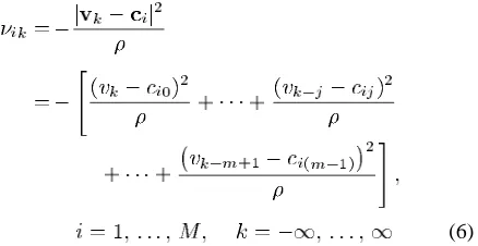
from evaluating the Euclidean norm in (5). Expanding the term gives
(6)
where is the delayed received signal and is the th component of the RBF center vector , which takes the values
of the scalar channel outputs . Note from
(6) that is a summation of the delayed components, and the scalar centers take the values of the scalar
channel outputs . Thus, we could reduce the
computational complexity of evaluating (6) by precalculating
, for all the possible
values of the scalar channel outputs and
storing the values. From (6) the value of can be obtained by summing the corresponding delayed values of , which we will define as
(7)
yielding
(8)
The reduced complexity computation of in (6) based on the scalar channel outputs can be represented as in Fig. 1. The mul-tiplexer (Mux) maps corresponding to the scalar center to the contribution of the vector center’s component .
The reduced computational complexity per equalized output sample of an -ary Jacobian DFE with inputs,
hidden RBF nodes derived from
[image:3.612.38.289.528.619.2]scalar centers is given in Table II. Comparing Tables I and II, we observe a substantial computational complexity reduction, especially for a high feedforward order , since , if . For example, for the 16 QAM BbB AQAM mode
Fig. 1. Reduced-complexity computation of in (6) for substitution in (5) based on the scalar channel outputs,r ; l = 1; . . . ; n .
TABLE II
REDUCED-COMPUTATIONALCOMPLEXITY PEREQUALIZEDOUTPUTSAMPLE OF ANM-ARYJACOBIANLOGARITHMICRBF DFE BASED ON THESCALAR
CENTERS. THEJACOBIANRBF DFE BASED ONEQUATION(5) HASm
INPUTS ANDn HIDDENRBF NODES, WHICHAREDERIVEDFROM THEn NUMBER OFSCALARCENTERS
of our system we have and for the RBF
DFE equalizer parameters of , and . The total complexity reduction is by a factor of about 1.3. If we increase the RBF DFE feedforward order and use the equalizer
parame-ters of , and —which gives a better BER
per-formance—then we have and —and
the total complexity reduction is by a factor of about 2.1. The computational complexity can be further reduced by neglecting the RBF scalar centers situated far from the received signal , since the contribution of the RBF scalar centers to the deci-sion function of (2) is inversely related to their distance from the received signal , as observed by Patra [29].
The performance of the RBF DFE and that of its Jacobian approximation was virtually identical, as demonstrated in [8]. However, due to lack of space here no explicit comparisons were included. Having presented the proposed reduced complexity Jacobian logarithmic RBF equalizer, we will proceed to intro-duce the combined RBF equalization and turbo-coding system and investigate its performance in both fixed QAM and BbB AQAM schemes.
III. SYSTEMOVERVIEW
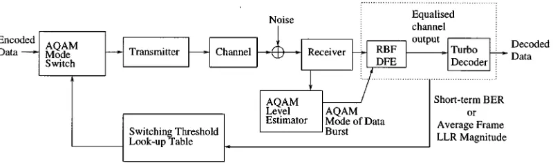
Fig. 2. System schematic of the joint adaptive modulation and RBF equalizer scheme using turbo coding.
symbol. The LLR of a data bit is denoted by , which is defined as the log of the ratio of the probabilities of the bit being a logical 1 or a logical 0, which is expressed here as:
(9)
The LLR of the bits representing the QAM symbols can be ob-tained from the a posteriori likelihood of the symbol. We pro-vide an example for the 4 QAM mode of our AQAM scheme. The a posteriori likelihood , , and of the four pos-sible 4 QAM symbols is given by the Jacobian RBF networks. A 4 QAM symbol is denoted by the bits and the symbols , , , and correspond to 00, 01, 10 11, respectively. Thus, the a posteriori LLRs of the bits are obtained as follows:
(10)
where
(11)
and is the Jacobian logarithmic relationship of (4). Note that the Jacobian RBF equalizer will provide
number of bit-LLR values for every -QAM symbol, which are fed to the turbo-channel decoder as its soft inputs. The turbo decoder iteratively improves the BER of the decoded bits and the detected bits are constituted by the sign of the turbo de-coder’s soft output. An iterative turbo equalizer can be con-structed by feeding back the posteriori information obtained by the turbo decoder to the RBF equalizer. Reference [30] shows
approximately 1.5 - and 3-dB channel SNR improvement for fixed-mode BPSK and 4 QAM, respectively, at a BER of 10 after the second turbo-equalizer iteration. The channel used in [30] was a three-path equal-weight Rayleigh fading channel with normalized Doppler frequency of 1.5 10 . However, turbo-equalized BbB AQAM constitutes our future research.
The probability of error for the detected bits can be estimated on the basis of the soft output of the turbo decoder. Referring
to (9) and assuming , the
probability of error for the detected bits is given by
if
if
(12)
The probability of a bit having the value of 1 or 1 can be rewritten in terms of its LLR as follows:
(13)
Upon substituting (13) into (12), we redefined the probability of error of a detected bit in terms of its LLR as
(14)
where is the magnitude of . The average
short-term probability of bit error within the decoded transmis-sion burst is given by
(15)
where is the number of decoded bits per transmitted burst and is the th decoded bit in the frame. This value, which we will refer to as the estimated short-term BER estimates the actual BER of the frame, where the actual BER is the ratio of the number of bit errors encountered in a data burst to the total number of bits transmitted in that burst.
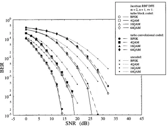
Fig. 3. Probability of bit error versus SNR performance for the Jacobian logarithmic RBF DFE using the turbo codec of Table IV over the dispersive two-path fading channel of Table III for various QAM schemes. The equalizer has a feedforward order ofm = 2, feedback order of n = 1 and a decision delay of = 1 symbol. The number of convolutional and BCH turbo decoder iterations is six, while the turbo-interleaver size is fixed to 9984 bits.
IV. TURBO-CODEDRBF-EQUALIZED -QAM PERFORMANCE
RESULTS
In this section we characterize the performance of the RBF DFE assisted and turbo-coded -QAM scheme. High channel code rates in excess of 2/3 are desirable, in order to maximize the BPS throughput of the system. Consequently, block codes were favored as the component code in preference to the Recur-sive Systematic Convolutional (RSC) code based turbo-coded benchmarker scheme, since turbo-block coding has been shown to perform better for coding rates above 2/3 [31]. This is demon-strated first in Fig. 3, which will be discussed in more depth at a later stage. In our simulations, unless otherwise stated, we hence utilized the turbo-coding parameters given in Table IV1
and employed the 288- s-duration FMA1 nonspread data trans-mission burst structure specified in the FRAMES proposal [32]. The turbo encoder used two Bose–Chaudhuri–Hocquenghem BCH(31, 26) block codes in parallel. A 9984-bit random inter-leaver was used between the two component codes, unless oth-erwise stated. We used the Log-MAP decoder [27] throughout our investigations, since it offered the same performance as the optimal MAP decoder at a reduced complexity. The RBF DFE used in our simulations had a feedforward order of , feedback order of and decision delay of symbol. Increasing the feedforward order and decision delay would in-crease the performance of the fixed mode, especially for higher-order modulation modes, albeit at the expense of an exponential computational complexity increment. For example, according to Table II, the 16 QAM Jacobian RBF DFE having a feedforward order of , feedback order of and decision delay
1The parity bits were not punctured, since block turbo codes suffer from
per-formance loss upon puncturing.
TABLE III
SIMULATIONPARAMETERS FORTWO-PATHRAYLEIGHFADINGCHANNEL
of has a computational complexity more than 16 times higher compared to the 16 QAM Jacobian RBF DFE having a
feedforward order of , feedback order of and
decision delay of . The RBF DFE used correct symbol feedback and we assumed perfect CIR estimation, hence the as-sociated results indicate the system’s best-case performance.
TABLE IV
TURBOBCHANDRSC CODINGPARAMETERS
turbo codec, at the cost of a higher computational complexity. As seen in Table IV, a half rate RSC encoder of constraint length was used in the RSC turbo codec. The generator poly-nomials expressed in octal terms were set to 23 (for the feed-back path) and 35. Similarly to the turbo BCH codec, the code rate was set to 0.75 by applying a random puncturing pattern in the RSC encoder. The turbo-interleaver depth was also chosen to be 9984 bits. We employed the same simplified technique as in [33] for estimating the various schemes’ relative complexity, where the number of trellis transitions per information bit was the basis of our comparisons. Employing the equations derived in [33], we found that the estimated complexity of BCH(31,26) turbo codec and RSC(2,1,5) turbo codec are 2039 ad 1152, re-spectively. The complexity of the BCH(31,26) turbo codec is a factor of (2039/1152 ) 1.77 higher than that of the RSC(2,1,5) turbo codec. Since we are aiming for the best possible system performance, the BCH(31,26) turbo codec was used instead of the RSC(2,1,5) turbo codec for our AQAM scheme simulations at the cost of a higher computational complexity.
In our proposed turbo-coding assisted, RBF DFE BbB AQAM scheme of Fig. 2 we invoked the short-term BER estimates of (14) and (15) in controlling the AQAM modem modes. Explicitly, in Fig. 2 the Jacobian RBF DFE LLRs provide an estimate of the BER of the current AQAM burst, and on the basis of this BER estimate the remote AQAM transmitter is instructed by superimposing a 2-bit AQAM mode request message upon the receiver’s own transmitted burst in order to invoke the transmission mode deemed to provide the highest BPS throughput, while meeting our target BER requirement [1], [8], [23]. Due to lack of space these issues are beyond the scope of this contribution and we have assumed zero-delay perfect AQAM mode signaling. For a deeper discussion on this topic the reader is referred to [4], while the associated co-channel interference aspects were treated in [34].
V. TURBOCODINGASSISTEDBbB AQAM RBF DFE PERFORMANCE
A. System Overview
As discussed in Section III, the probability of bit errors is re-lated to the magnitude of the bit LLR according to (14). The BCH(31, 26) turbo decoder iteratively improves the BER of the decoded bits. The average value of the LLR magnitude of all bits
in the transmission burst after equalization can be used for es-timating the average probability of error of the turbo BCH(31, 26) decoded frame. Thus, the average frame LLR magnitude provided by the equalizer can be used as the BbB AQAM mode switching criterion. We define the average frame LLR magni-tude as follows:
(16)
where is the number of data bits per transmitted frame and is the th data bit in the frame.
Again, the schematic of the proposed turbo-coded AQAM RBF DFE arrangement is depicted in Fig. 2. The average frame LLR magnitude of (16) generated by the RBF DFE is compared to a set of switching LLR magnitude thresholds, bearing in mind the current AQAM mode of the equalized data burst. Conse-quently, a modulation mode is selected for the next transmis-sion burst, based on the current estimated BER upon assuming slowly fading channels. More explicitly, this implies that the similarity of the average frame LLR magnitude of consecutive data bursts can be exploited, in order to set the next modula-tion mode. The modulamodula-tion modes utilized in our system are BPSK, 4 QAM, 16 QAM, 64 QAM and no transmission (NO TX). Therefore, the modulation mode is switched according to the average frame LLR magnitude as follows:
Modulation Mode
if
if
if
if
if
(17)
where are the switching LLR magnitude
thresholds corresponding to the various -QAM modes. The switching LLR magnitude thresholds corresponding
to -QAM, , can be obtained by
estimating the average frame LLR magnitude degradation/im-provement, upon switching the modulation mode from the current -QAM mode to a higher/lower number of bits per symbol. The target BER requirement can be met by obtaining the average frame LLR magnitude of each modulation mode corresponding to the estimated channel quality and by acti-vating the specific AQAM mode satisfying this target BER. In adapting the modulation mode, an AQAM mode signaling regime has to be implemented in order to harmonize the operation of the transmitter and receiver, for example using the regime proposed in [35].
B. Simulation Results
TABLE V
RANDOMINTERLEAVERSIZES FOREACHAQAM MODULATIONMODE OF(17)
TOFACILITATEBbB DECODING ANDUSING THE288 MICROSECONDSFMA1 NONSPREADDATATRANSMISSIONBURSTSTRUCTURESPECIFIED IN THE
FRAMES PROPOSAL[32]
the transmitter filter, the wireless channel and the receiver filter. We used square root Nyquist pulse-shaping and we as-sumed that the pulse-shaping does not introduce intersymbol interference to the overall system. We do acknowledge that a more realistic outdoor mobile channel model may have more than two taps. The symbol-spaced two-path channel had a total dispersion of about 400 ns at the 2.6 MBd signaling rate used, which is associated with a path-length difference of 128 m prevalent in pico- or microcellular scenarios. The wide-band fading channel was burst-invariant, implying that during a transmission burst the CIR was considered time-invariant. In our simulations, we used the Jacobian RBF DFE having a
feedforward order of , feedback order of and
decision delay of . We used the BCH(31, 26) code of Table IV as the turbo-component code and a variable-length random interleaver depending on the BPS throughput of the modulation mode used, as given in Table V, in order to en-able BbB decoding. We also note that we do not utilize a channel interleaver because of the less bursty nature of the error distribution in conjunction with the AQAM scheme, than in a fixed high-order modulation schemes where dropping the number of bits per symbol is infeasible. The AQAM scheme always attempts to invoke the appropriate modulation mode for reducing the probability of encountering a received trans-mitted burst having a high instantaneous BER. The modulation modes utilized in our system are BPSK, 4 QAM, 16 QAM, 64 QAM and NO TX. During the beginning of a sequence of bursts, where the channel conditions are not known precisely, BPSK namely, the most robust modulation mode, is used. We also assume that the receiver has perfect knowledge of the modulation mode used in its received transmission burst. In a practical system, the transmitter notifies the receiver of all the AQAM mode changes and control symbols must be used for conveying the modulation mode employed by the transmitter to the receiver, for example using the regime of [35].
In our experiments, we obtained the LLR magnitude degra-dation/improvement upon switching from each AQAM mode to all other legitimate modes under the same instantaneous channel conditions. As an example, Fig. 4 shows the estimated short-term BER—defined in (15)—that would be encountered upon switching to all possible AQAM modes after BCH(31,26) turbo decoding versus the average frame LLR magnitude of 4QAM before decoding, which was the current AQAM mode. Each point in Fig. 4 represents the decoder’s estimated short-term BER (specified by the -axis) for a particular received data burst using the corresponding modulation mode and the average frame LLR magnitude (specified by the -axis) of that burst before decoding, when the current AQAM
Fig. 4. The estimated short-term BER for all the possible BCH(31,26) turbo-decoded AQAM modes versus the average frame LLR magnitude of 4QAM over the two-path Rayleigh fading channel of Table III. The figure illustrates the expected spread of the short-term BER of all turbo-decoded modem modes given a certain average frame LLR magnitude value in conjunction with 4QAM as the current modem mode.
mode is 4 QAM, which was calculated using (16). In order to maintain the target BER of 10 , Fig. 4 demonstrates how each
switching LLR magnitude is obtained
after averaging the LLR occurrences seen in the figure. More explicitly, the average frame LLR magnitudes encountered in the 4 QAM transmission burst would have to be 4.0, 7.5, 40.0 and 100.0, before switching to BPSK, 4 QAM, 16 QAM and 64 QAM AQAM bursts under the same channel conditions, leading to an estimated BER of 10 after BCH(31, 26) turbo decoding, as seen in bold in Table VI. For example, if the average LLR magnitude of the received 4 QAM transmission
burst, is in the range of , in Fig. 4
the modulation mode is switched from 4 QAM to 16 QAM for the next AQAM burst, since the BER of this 16 QAM transmis-sion burst is estimated to be below the target BER of 10 . Note that due to the spreading of the average frame LLR magnitude versus the short-term BER curve in Fig. 4—especially for higher-order AQAM modes—the threshold is estimated from the mean of this dynamic range. Using the same method for the other modulation modes, the switching LLR magnitude thresholds were obtained for the turbo-decoded target BER of 10 , as listed in Table VI.
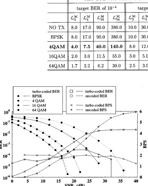
Fig. 5 shows the performance comparison of the AQAM Ja-cobian RBF DFE scheme in conjunction with turbo BCH(31,26) coding for a target BER of 10 along with its constituent turbo-coded fixed QAM modes. Fig. 5 also shows the BER and BPS performance of the AQAM/RBF DFE scheme without turbo coding, with the short-term BER as the switching criterion as described in [23] for performance comparison. The switching BER thresholds of the AQAM/RBF DFE scheme without turbo coding were listed in Table VII.
TABLE VI
THESWITCHINGLLR MAGNITUDETHRESHOLDSL OF THETURBOBCH(31,26)-ASSISTEDRBF DFE BbB AQAM SCHEME FOR THETARGETBEROF10
AND FOR THEZERO-ERRORTARGETPERFORMANCEOVER THETWO-PATHRAYLEIGHFADINGCHANNEL OFTABLEIII
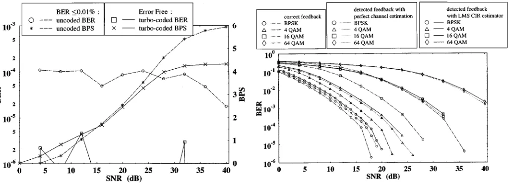
Fig. 5. BER and BPS performance of the turbo BCH(31,26)-coded AQAM Jacobian RBF DFE for a data-transmission target BER of 10 using the parameters listed in Table III. The modem mode used the “before-decoding” LLR switching criterion for this scheme with the thresholds listed in Table VI. The Jacobian RBF DFE had a feedforward order ofm = 2, feedback order ofn = 1 and decision delay of = 1 symbol. The turbo-coding parameters were given in Table IV and the number of turbo-decoder iterations was six. The turbo-interleaver size was fixed according to the modulation modes used, as shown in Table V.
TABLE VII
SWITCHINGBER THRESHOLDSP OF THEUNCODEDRBF DFE BbB AQAM SCHEME FOR THETARGETBEROF10 OVER THETWO-PATH
RAYLEIGHFADINGCHANNEL OFTABLEIII
gain of 4 dB at a channel SNR of 0 dB. However, at high SNRs the BPS performance is limited by the turbo-coding rate of the
system to a maximum BPS throughput of .
The turbo BCH(31, 26)-coded AQAM system also exhibited a superior BER performance, when compared to the uncoded
system for the average channel SNR range of 0 to 16 dB and for the range above 28 dB. The turbo BCH(31,26)-coded AQAM system failed to achieve the target BER of 10 in the SNR range of 16 dB to 28 dB. This is because the spread nature of the short-term BER versus LLR magnitude curves in Fig. 4 leads to inaccuracies in obtaining these LLR magnitude thresh-olds, especially for and . These inaccuracies affect the switching performance for the SNR range of 16 dB to 28 dB. The spread nature of the short-term BER versus LLR magni-tude curves in Fig. 4 is due to a number of factors and these investigations are set aside for future work.
Since the estimated short-term BER in Fig. 4 is a somewhat erratic function of the turbo-decoder’s input LLR, the switching LLR values have to be conservative, if the target BER cannot be exceeded. For the BER 10 scenario the switching LLR can be adjusted to be near the upper end of the LLR-range ob-served in Fig. 4. When aiming for virtually error-free commu-nications, an even more conservative LLR threshold has to be chosen, in order not to precipitate a plethora of transmission er-rors, even at the cost of thereby reducing the achievable BPS throughput of the system. Recent studies of the SNR-dependent AQAM switching thresholds can be found in [35]–[37]. Our fu-ture research will explore the feasibility of finding a real-time adaptive learning algorithm for providing optimized switching thresholds for the AQAM scheme online. Fig. 6 shows the BER and BPS performance of the near-zero target BER turbo-coded AQAM Jacobian RBF DFE scheme with the more conservative, i.e., increased LLR magnitude based switching thresholds listed in Table VI. The BER and BPS performance of the uncoded AQAM RBF DFE system is also characterized in the figure for comparison. The BPS performance of the coded system was better, than that of the uncoded AQAM system for the average channel SNR range of 0–15 dB, as evidenced by Fig. 6. How-ever, the BPS throughput was limited by the 26/36 coding rate
of the system to a maximum value of at high
[image:8.612.64.267.577.678.2]Fig. 6. The BER and BPS performance of the joint AQAM/Jacobian RBF DFE with turbo BCH(31,26) coding for near-zero target BER transmission using the parameters listed in Table III. The modem mode used “before decoding” LLR switching criterion for this scheme with the thresholds listed in Table VI. The Jacobian RBF DFE had a feedforward order ofm = 2, feedback order ofn = 1 and decision delay of = 1 symbol. The turbo-coding parameter is given in Table IV and the number of turbo-decoder iterations is 6. The turbo-interleaver size is fixed according to the modulation mode used as shown in Table V.
AQAM modes does not lead to high intercell interference, un-like schemes that use power control in an effort to maintain a given SNR and thereby spilling energy into adjacent cells. In other words, the AQAM modem unobtrusively adjust its own modulation mode in order to best exploit the SNR available and to attain the highest possible BPS throughput in arbitrary un-known propagation environments.
We will now investigate the effects of imperfect channel es-timation and error propagation of the RBF DFE on our system. We will first investigate the effects of error propagation. Again, the simulation parameters used are listed in Table III and the turbo-interleaver length varies according to the modulation mode used, as seen in Table V. Fig. 7 shows the performance degradation due to error propagation in the RBF DFEs decision feedback loop. We first study the performance using perfect channel estimation. The performance degradation increases when using high-order QAM modes. The performance degra-dations at a BER of 10 are 1, 2, 8, and 12 dB for BPSK, 4 QAM, 16 QAM, and 64 QAM, respectively. Hence a new set of AQAM switching LLRs were obtained according to Fig. 4, but with the detected decision feedback. The corresponding values are given at the right half of Table VI. In conclusion of these investigations Fig. 8 shows that the BER performance of the turbo-coded AQAM/RBF DFE, which is similar with and without the effects of error propagation. This shows that the AQAM switching mechanism is capable of maintaining the targeted BER, since the RBF DFE retains its ability to estimate the channel quality even in the presence of decoding errors. The BPS performance degrades however significantly, especially at medium SNRs due to the more grave performance degradation of the higher-order AQAM modes induced by the error propagation of the RBF DFE. For example, the BPS throughput reduction is approximately 1.6 BPS at a channel
Fig. 7. Probability of bit error versus SNR performance comparison for the Jacobian logarithmic RBF DFE using the turbo codec of Table IV with error propagation and without error propagation over the dispersive two-path fading channel of Table III for various QAM schemes. The LMS channel estimator has a step-size of 0.1. The equalizer has a feedforward order of m = 2, feedback order of n = 1 and a decision delay of = 1 symbol. The number of convolutional and BCH turbo-decoder iterations is six, while the turbo-interleaver size is fixed according to the modulation mode used as shown in Table V.
Fig. 8. The BER and BPS performance of the turbo BCH(31,26)-coded joint AQAM/Jacobian RBF DFE with correct and detected decision feedback for a data-transmission target BER of 10 using the parameters listed in Table III. The LMS channel estimator has a step-size of 0.1. The modem mode used “before decoding” LLR switching criterion for this scheme with the thresholds listed in Table VI for correct decision feedback and detected decision feedback. The Jacobian RBF DFE had a feedforward order ofm = 2, feedback order ofn = 1 and decision delay of = 1 symbol. The turbo-coding parameter is given in Table IV and the number of turbo-decoder iterations is 6. The turbo-interleaver size is fixed according to the modulation mode used as shown in Table V. Observe that the BPS legends associated with perfect as well as LMS-based CIR estimation, where in both cased using detected feedback, coincide with each other.
SNR of 24 dB. Further research is required for mitigating the effects of error propagation, especially in high-order AQAM modes, in order to improve the BER performance.
[image:9.612.301.555.348.509.2]of AQAM. The average BER reaches 10 , which is an order of magnitude higher than the target BER of 10 . Nevertheless, in order to achieve the target BER of 10 , we have to adjust the LLR magnitude based switching thresholds to more conser-vative values for compensating for the imperfect CIR estima-tion, as seen in Table VI. Our experimental results not included here show that this is achieved at a negligible reduction of the throughput.
Overall, we have demonstrated that an RBF assisted BbB AQAM scheme is capable of adapting to the time-variant channel quality fluctuations, estimated for example by the RBF equalizer of the system, in order to achieve a given target BER, while maintaining the highest possible BPS throughput.
VI. CONCLUSION
In conclusion, the performance of the RBF DFE has been doc-umented in the context of fixed-mode modulation schemes in [6] and [7]. However, there is little information concerning its po-tential in either BbB AQAM or in FEC-coded scenarios, despite the advantageous interactions of RBF-aided DFE BbB AQAM in conjunction with turbo FEC, which were demonstrated in our preliminary work [8]. In this contribution the complexity of the RBF DFE was reduced upon invoking the Jacobian logarithmic approximation of (4) for avoiding the evaluation of exponen-tial functions in the RBF DFE. We have shown that the average frame LLR at the input of the turbo decoder can be used as an effective metric for adapting the AQAM modes according to the time-variant channel conditions.
The turbo-coded AQAM RBF DFE system exhibited a better BPS performance, when compared to the uncoded system at low to medium channel SNRs, as evidenced by Fig. 5. The same figure also showed an improved coded BER performance at higher channel SNRs. A virtually error-free turbo-coded AQAM scheme was also characterized in Fig. 6. Our future work is tar-geted at invoking turbo equalization and adaptive beam-steering, in order to reduce the effects of co-channel interference.
REFERENCES
[1] W. T. Webb and R. Steele, “Variable rate QAM for mobile radio,” IEEE
Trans. Commun., vol. 43, pp. 2223–2230, July 1995.
[2] S. Sampei, S. Komaki, and N. Morinaga, “Adaptive modulation/TDMA scheme for large capacity personal multimedia communications sys-tems,” IEICE Trans. Commun., vol. E77-B, pp. 1096–1103, Sept. 1994. [3] A. J. Goldsmith and S. G. Chua, “Variable rate variable power MQAM for fading channels,” IEEE Trans. Commun., vol. 45, pp. 1218–1230, Oct. 1997.
[4] J. M. Torrance and L. Hanzo, “Latency and networking aspects of adap-tive modems over slow indoors Rayleigh fading channel,” IEEE Trans.
Veh. Technol., vol. 48, pp. 1237–1251, July 1999.
[5] C. H. Wong and L. Hanzo, “Channel capacity upperbound of a wideband burst-by-burst adaptive modem,” in Proc. IEEE Veh. Technol. Conf., May 1999, pp. 1851–1855.
[6] S. Chen, S. McLaughlin, and B. Mulgrew, “Complex-valued radial basis function network, Part II: Application to digital communications channel equalization,” EURASIP Signal Processing, vol. 36, pp. 175–188, Mar. 1994.
[7] M. S. Yee and L. Hanzo, “Multi-level radial basis function network based equalisers for Rayleigh channels,” in Proc. IEEE Veh. Technol.
Conf., May 16–19, 1999, pp. 707–711.
[8] M. S. Yee, T. H. Liew, and L. Hanzo, “Block turbo coded burst-by-burst adaptive radial basis function decision feedback equaliser assisted modems,” in Proc. IEEE Veh. Technol. Conf., vol. 3, Amsterdam, The Netherlands, Sept. 1999, pp. 1600–1604.
[9] G. J. Gibson, S. Siu, and C. F. N. Cowan, “The application of nonlinear structures to the reconstruction of binary signals,” IEEE Trans. Signal
Processing, vol. 39, pp. 1877–1884, Aug. 1991.
[10] , “Multi-layer perceptron structures applied to adaptive equalizers for data communications,” in ICASSP, IEEE Int. Conf. Acoust., Speech,
Signal Processing, May 1989, vol. 2, pp. 1183–1186.
[11] S. Siu, G. J. Gibson, and C. F. N. Cowan, “Decision feedback equaliza-tion using neural network structures and performance comparison with standard architecture,” IEE Proc., vol. 137, pp. 221–225, Aug. 1990. [12] S. Chen, G. J. Gibson, and C. F. N. Cowan, “Adaptive channel
equaliza-tion using a polynomial-perceptron structure,” Proc. Inst. Elect. Eng., vol. 137, pp. 257–264, Oct. 1990.
[13] W. S. Gan, J. J. Soraghan, and T. S. Durrani, “New functional-link based equaliser,” Electron. Lett., vol. 28, pp. 1643–1645, Aug. 1992. [14] T. Kohonen, O. Simula, A. Visa, and J. Kangas, “Engineering
applica-tions of the self-organizing map,” Proc. IEEE, vol. 84, pp. 1358–1384, Oct. 1996.
[15] J. C. Sueiro, A. A. Rodriguez, and A. R. F. Vidal, “Recurrent radial basis function networks for optimal symbol-by-symbol equalization,”
EURASIP Signal Processing, vol. 40, pp. 53–63, Oct. 1994.
[16] S. Chen, B. Mulgrew, and P. M. Grant, “A clustering technique for dig-ital communications channel equalization using radial basis function net-works,” IEEE Trans. Neural Networks, vol. 4, pp. 570–579, July 1993. [17] S. Chen, B. Mulgrew, and S. McLaughlin, “Adaptive Bayesian equalizer
with decision feedback,” IEEE Trans. Signal Processing, vol. 41, pp. 2918–2927, Sept. 1993.
[18] H. L. V. Trees, Detection, Estimation and Modulation Theory, Part
1. New York: Wiley, 1968.
[19] S. Chen, S. McLaughlin, B. Mulgrew, and P. M. Grant, “Bayesian deci-sion feedback equaliser for overcoming co-channel interference,” Proc.
Inst. Elect. Eng., vol. 143, pp. 219–225, Aug. 1996.
[20] S. Chen, B. Mulgrew, E.-S. Chng, and G. J. Gibson, “Space translation properties and the minimum-BER linear-combiner DFE,” Proc. Inst.
Elect. Eng., vol. 145, pp. 316–322, Oct. 1998.
[21] L. Hanzo, W. T. Webb, and T. Keller, Single-and Multicarrier
Quadra-ture Amplitude Modulation. New York: Wiley, IEEE, 2000. [22] M. S. Yee and L. Hanzo, “Upper bound performance of radial basis
func-tion decision feedback equalised burst-by-burst adaptive modulafunc-tion,” in
ECMCS’99 Krakow, Poland, June 24–26, 1999, CD-ROM. [23] M. S. Yee and L. Hanzo, “Radial basis function decision feedback
equaliser assisted burst-by-burst adaptive modulation,” in Proc. IEEE
Globecom’99, Rio de Janeiro, Brazil, Dec. 5–9, 1999, pp. 2183–2187.
[24] C. Berrou, A. Glavieux, and P. Thitimajshima, “Near Shannon limit error-correcting coding and decoding: Turbo codes,” in Proc. IEEE Int.
Conf. Commun.: IEEE, May 1993, pp. 1064–1070.
[25] P. Robertson, P. Hoeher, and E. Villebrun, “Optimal and sub-optimal maximum a posteriori algorithms suitable for turbo decoding,” Euro.
Trans. Telecommun., vol. 8, 1997.
[26] D. S. Broomhead and D. Lowe, “Multivariable functional interpolation and adaptive networks,” Complex Systems, vol. 2, pp. 321–355, 1988. [27] P. Robertson, E. Villebrun, and P. Hoeher, “A comparison of optimal and
sub-optimal MAP decoding algorithms operation in the log domain,” in
IEEE Int. Conf. Commun., June 1995, vol. 2, pp. 1009–1013.
[28] J. Erfanian, S. Pasupathy, and G. Gulak, “Reduced complexity symbol detectors with parallel structures for ISI channels,” IEEE Trans.
Commun., vol. 42, pp. 1661–1671, Feb./Mar./Apr. 1994.
[29] S. K. Patra and B. Mulgrew, “Computational aspects of adaptive ra-dial basis function equalizer design,” in IEEE Int. Symp. Circuits Syst.
ISCAS’97, June 1997, vol. 1, pp. 521–524.
[30] M. S. Yee, B. L. Yeap, and L. Hanzo, “Radial basis function assisted turbo equalization,” in Proc. IEEE Veh. Technol. Conf., May 15–18, 2000. [31] J. Hagenauer, E. Offer, and L. Papke, “Iterative decoding of binary
block and convolutional codes,” IEEE Trans. Inform. Theory, vol. 42, pp. 429–445, Mar. 1996.
[32] A. Klein, R. Pirhonen, J. Sköld, and R. Suoranta, “FRAMES multiple ac-cess mode 1—Wideband TDMA with and without spreading,” in Proc.
PIMRC’97, Sept. 1997, pp. 37–41.
[33] T. Liew, J. Pliquett, B. Yeap, L.-L. Yang, and L. Hanzo, “Concatenated space time block codes and TCM, turbo TCM, convolutional as well as turbo codes,” in GLOBECOM 2000, San Francisco, CA, Nov. 27–Dec. 1, 2000, pp. 2292–2301.
[34] J. M. Torrance, L. Hanzo, and J. Keller, “Interference aspects of adaptive modems over slow Rayleigh fading channel,” IEEE Trans. Veh. Technol., vol. 48, pp. 1527–1545, Sept. 1999.
[36] B. Choi, M. Münster, L. Yang, and L. Hanzo, “Performance of rake receiver assisted adaptive-modulation based cdma over frequency selective slow Rayleigh fading channels,” Electron. Lett., vol. 37, pp. 247–248, Feb. 15, 2001.
[37] J. Torrance and L. Hanzo, “Demodulation level selection in adaptive modulation,” Electron. Lett., vol. 32, pp. 1751–1752, Sept. 12, 1996. [38] J. G. Proakis, Digital Communications. New York: McGraw-Hill,
1995.
M. S. Yee (S’97–A’00) received the B.Eng. degree
in electronics engineering and the Ph.D. degree in telecommunications in 2001, both from the Univer-sity of Southampton, U.K.
Currently, she is continuing her research as a Post-doctoral Research Fellow. Her research interests are in the field of neural network-based algorithms and their application to various wireless communications problems. She has published numerous papers in this field.
T. H. Liew received the B.Eng. degree in electronics
engineering and the Ph.D. degree in telecommu-nications in 2001, both from the University of Southampton, U.K.
Currently, he is continuing his research as a Post-doctoral research fellow. His research interests are associated with coding and modulation for wireless channels, space-time coding, adaptive transceivers, etc. He has published his research results widely.
Lajos Hanzo (M’91–SM’92) graduated in
elec-tronics in 1976. He received the Ph.D. degree from the Technical University of Budapest, Hungary, in 1983.