Adaptive Pi Controller Based Control of Spu for Maintaining
Constant Cpi Voltages
G NARESH BABU
1& K.KRANTHI PRATAP SINGH
21
M.Tech Scholar, Dept of EEE, ASR College of Engineering and Technology, JNTUK, A.P
2
Assistant Professor, Dept of EEE, ASR College of Engineering and Technology, JNTUK, A.P
Abstract
Solar photo Voltaic (SPV) systems based grid interfacing systems involve two stage power conversions. This conversion requires Maximum Power Point Tracking (MPPT) based boost converter that can supply a constant DC link voltage with a SPV as its input as the first stage. The second stage conversion involves a two-level Voltage Source Converter (VSC) that serves as an inverter which feed power from the boost converter to the grid. To meet the grid requirements the voltage at the Common Point of Interconnection (CPI), the voltage of the inverter must be made equal to the voltage of CPI. This can be done adjusting DC link voltage of stage one of the converter. This can be achieved by using anadaptive feed forward Proportional and integral Controller (PI). The advantage of this controller is that it improves dynamic response, reduces the switching losses and provides robust response under grid voltage variations. The performance of the system is verified with the help of MATLAB based simulation studies and the case studies are presented.
1.
Grid Interfaced Systems
1
.0 Introduction
The importance for sustainable energy
sourceshas been increasing for the past two decades
becauseof scarcities of fossil fuel and global
warming.Nowadays the most admirable energy
sources outall renewable energy sources are wind
energy andsolar energy because of advancement in
powerelectronics techniques. Especially Solar
electricenergy became most popular because of
advisementin manufacturing technologies and cost
advantages In solar energy system inverter is the
main partwhich converts DC power obtained from
solar cellsin to AC power to fed in to the Grid.
NowadaysMultilevel inverters are drawing attention
fromresearchers and manufacturers due to their
morebenefits over conventional three level pulse
widthmodulated inverter [PWM] inverters. They
offerimproved output waveforms, smaller filter size,
lowerEMI, lower total harmonic distortion (THD),
and others
The three common topologies for multi level
inverters are as follows:
1) Diode clamped (neutral clamped)
2) Capacitor clamped (flying capacitors)
and 3) Cascaded H-bridge inverter
Figure 1.1: Carrier
In addition, several modulation and control
strategies have been developed or adopted
formultilevel inverters, including the following
:multilevel sinusoidal (PWM), multilevel selective
harmonic elimination, and space-vector modulation
A typical single-phase five-level inverter
adopts full-bridge configuration by using
approximate sinusoidal modulation technique as the
powercircuits. The output voltage then has the
followingfive values: zero, +1/2Vdc, Vdc,-1/2Vdc
and –Vdc(assuming that Vdc is the supply voltage).
Theharmonic components of the output voltage
aredetermined by the carrier frequency and
switchingfunctions. Therefore, their harmonic
reduction islimited to a certain degree.
To overcome this limitation, this paper
presents a13 level PWM inverter whose output
voltage can berepresented in the following 13 levels:
zero, +1/12Vdc, +1/6 Vdc, +1/4 Vdc, +1/3 Vdc,
+5/12 Vdc, +1/2Vdc, 1/2Vdc, 5/12Vdc, 1/3Vdc,
-1/4Vdc, -1/6Vdc and -1/12Vdc. As the number of
output levels increases,the harmonic content can be
reduced. This invertertopology uses two reference
signals, instead of onereference signal, to generate
PWM signals for theswitches. Both the reference
signals Vref1 and Vref2 areidentical to each other,
except for an offset valueequivalent to the amplitude
of the carrier signalVcarrier, as shown in Fig.1.
Because the inverter isused in a PV system, a
proportional–integral (PI)current control scheme is
employed to keep theoutput current sinusoidal and to
have high dynamicperformance under rapidly
changing atmosphericconditions and to maintain the
power factor at nearunity. Simulation and
experimental results arepresented to validate the
proposed inverterconfiguration.
THE PHOTOVOLTAIC SYSTEM
A PV system consists of a number of
interconnected
components
designed
to
accomplish a desired task, which may be to feed
electricity into the main distribution grid, to
pump water from a well, to power a small
calculator or one of many more possible uses of
solar-generated electricity. The design of the
system depends on the task it must perform and
the location and other site conditions under
which it must operate. This section will consider
the components of a PV system, variations in
design according to the purpose of the system,
system sizing and aspects of system operation
and maintenance.
SYSTEM DESIGN
There
are
two
main
system
configurations – stand-alone and grid-connected.
As its name implies, the stand-alone PV system
operates independently of any other power
supply and it usually supplies electricity to a
dedicated load or loads. It may include a storage
facility (e.g. battery bank) to allow electricity to
be provided during the night or at times of poor
sunlight levels. Stand-alone systems are also
often referred to as autonomous systems since
their operation is independent of other power
sources. By contrast, the grid-connected PV
system operates in parallel with the conventional
electricity distribution system. It can be used to
feed electricity into the grid distribution system
or to power loads which can also be fed from the
It is also possible to add one or more
alternative power supplies (e.g. diesel generator,
wind turbine) to the system to meet some of the
load requirements. These systems are then
known as „hybrid‟ systems.
Hybrid systems can be used in both
stand-alone and grid-connected applications but
are more common in the former because,
provided the power supplies have been chosen to
be complementary, they allow reduction of the
storage requirement without increased loss of
load probability. Figures below illustrate the
schematic diagrams of the three main system
types.
Fig.Schematic diagram of a stand-alone
photovoltaic system.
Fig.Schematic diagram of grid-connected
photovoltaic system.
Fig.
Schematic diagram of hybrid system
incorporating a photovoltaic array and a motor
generator (e.g. diesel or wind).
Modeling and Case study
The use of two stage SPV generation system
has beenproposed by several
researchers.Conventionally aDC-DC converter is
used as first stage which serves the purposeof MPPT.
The duty ratio of DC-DC converter is so adjusted
thatPV array operates at MPP point. The second stage
is a grid tiedVSC (Voltage Source Converter) which
feeds the power intothe distribution system. A single
phase two stage grid tied PVgeneration system with
constant DC link voltage is shown. Moreover, the
three phase grid tied PV generation systemwith
constant DC link voltage control is also shown in
[21],[22]. The concept of loss reduction by adaptive
DC link voltagefor VSC in hybrid filters is shown in
[23], [24] wherein, the DClink voltage is adjusted
according to reactive power requirementof filter.
However, in the proposed system the DC link
voltageof VSC is made adaptive with respect to CPI
voltage variation.
Moreover, the circuit topologies in both the
systems are different. Therefore, the work presented
work.For proper control of VSC currents, the DC link
voltage reference is set more than peak of three phase
line voltages. Thelimitation for current control in
single-phase grid connectedconverter is shown in
[25]. Considering the variation of CPI(Common
Point of Interconnection) voltage, the reference
DClink voltage is kept above the maximum allowable
CPI voltage.
Therefore in case of fixed DC link voltage
control for VSC, thesystem always operates at a DC
link voltage corresponding toworst case condition.
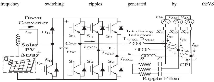
The system configuration for the proposed
system is shownin Fig. 1. A two stage system is
proposed for grid tied SPVsystem. The first stage is a
DC-DC boost converter serving forMPPT and the
second stage is a two-level three phase VSC.
The PV array is connected at the input of the boost converterand its input voltage is controlled such that PV array
delivers the maximum power at its output terminals. The outputof boost converter is connected to DC link of
VSC. The DClink voltage of VSC is dynamically adjusted by grid tied VSCon the basis of CPI voltage. The three
phase VSC consists ofthree IGBT legs. The output terminals of VSC are connected tointerfacing inductors and
the other end of interfacing inductorsare connected to CPI. A ripple filter is also connected at CPIto absorb high
frequency switching ripples generated by theVSC.
Figure : System Configuration under consideration
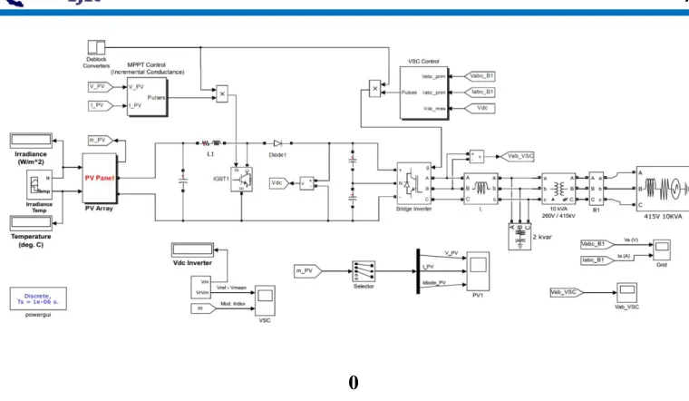
Model SIMULATION
With the available stability conditions the simulation model for the system configuration shown in fig 1 is
0
Figure 2:
MATLAB based schematic of Transformer less boost Converter
Figure 3:
MATLAB based model of MPPT Controller
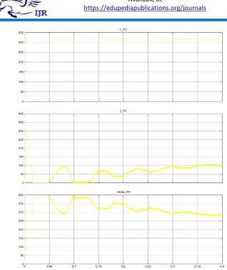
Figure 5:
Voltages and currents of MPPT based PV Cell
Figure 7:
Block Diagram of Voltage Source Converter
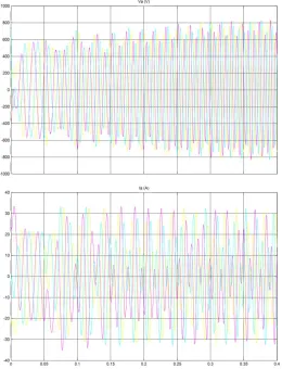
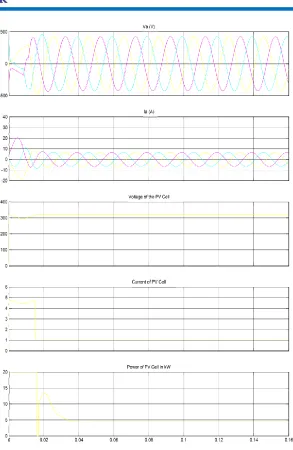
Figure 10:
Simulated performance for change in solar insolation with feedforward for PV
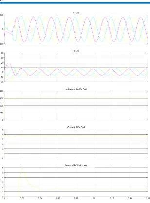
Figure 11:
Simulated performance fornormal to under voltage (415 V to 350 V),
Conclusion
A two-stage system has been modeled for three-phase
gridconnected solar PV generation. A composite InC
based MPPTalgorithm is used for control of the boost
converter. The performance of proposed system has
been demonstrated for widerange of CPI voltage
variation. A simple and novel adaptiveDC link
voltage control approach has been proposed for
control of grid tied VSC. The DC link voltage is
made adaptivewith respect to CPI voltage which
helps in reduction of lossesin the system. Moreover, a
PV array feed forward term is usedwhich helps in fast
dynamic response. An approximate linearmodel of
The PV arrayfeed forward term is so selected that it
is to accommodate for change in PV power as well as
for CPI voltage variation. Afull voltage and
considerable power level prototype has verified the
proposed concept. The concept of adaptive DC link
voltage has been proposed for grid tied VSC for PV
application however, the same concept can be
extended for all shunt connected grid interfaced
devices such as, STATCOM, D-STATCOM etc.This
system yields increased energy output using the same
model just by virtue of difference in DC linkvoltage
control structure.
Bibliography
[1]. M. Pavan and V. Lughi, “Grid parity in the
Italian commercial and industrial electricity
market,” in Proc. Int. Conf. Clean Elect. Power(ICCEP‟13), 2013, pp. 332–335.
[2]. M. Delfanti, V. Olivieri, B. Erkut, and G. A.
Turturro, “Reaching PV grid parity: LCOE
analysis for the Italian framework,” in Proc.
22nd Int. Conf.Exhib. Elect. Distrib.
(CIRED‟13), 2013, pp. 1–4.
[3]. H. Wang and D. Zhang, “The stand-alone PV
generation system with parallel battery
charger,” in Proc. Int. Conf. Elect. Control Eng. (ICECE‟10),2010, pp. 4450–4453.
[4]. M. Kolhe, “Techno-economic optimum sizing
of a stand-alone solar photovoltaic system,”
IEEE Trans. Energy Convers., vol. 24, no.
2,pp. 511–519, Jun. 2009.
[5]. D. Debnath and K. Chatterjee, “A two stage
solar photovoltaic based stand alone scheme
having battery as energy storage element for
rural deployment,” IEEE Trans. Ind. Electron.,
vol. 62, no. 7, pp. 4148–4157,Jul. 2015.
[6]. S. Krithiga and N. G. AmmasaiGounden,
“Power electronic configuration for the
operation of PV system in combined
grid-connected and stand-alone modes,” IET
Power Electron., vol. 7, no. 3, pp. 640–
647,2014.
[7]. I. J. Balaguer-Álvarez and E. I. Ortiz-Rivera,
“Survey of distributed generation islanding detection methods,” IEEE Latin Amer. Trans.,
vol. 8,no. 5, pp. 565–570, Sep. 2010.
[8]. C. A. Hill, M. C. Such, D. Chen, J. Gonzalez,
and W. M. Grady, “Battery energy storage for
enabling integration of distributed solar power
generation,” IEEE Trans. Smart Grid, vol. 3,
no. 2, pp. 850–857, Jun.2012.
[9]. [9] W. Xiao, F. F. Edwin, G. Spagnuolo, and
J. Jatskevich, “Efficient approaches for
modeling and simulating photovoltaic power
systems,” IEEE J. Photovoltaics, vol. 3, no. 1,
pp. 500–508, Jan. 2013.
[10].
P. Chiradeja, “Benefit of distributed generation: A line loss reduction analysis,” inProc. IEEE/PES Transmiss. Distrib. Conf.