A Simple Massive MIMO Scheme based on
the Overlap of STBC
Pooja Kenchetty. P1, Iimori Hiroki2, Giuseppe Thadeu Freitas de Abreu3, K. Rajesh Shetty4
PG Student, Department of Electronics and Communication Engineering, NMAMIT, Nitte, Karnataka, India1
Student, Department of Electrical Engineering, Ritsumeikan University, Japan2
Professor, Department of Electrical Engineering, Ritsumeikan University, Japan3
Professor, Department of Electronics and Communication Engineering, NMAMIT, Nitte, Karnataka, India4
ABSTRACT:The construction for Massive MIMO based on the overlap of Alamouti codes over the spatial dimension is proposed. In order to separate the overlapped streams at the receiver, the V-BLAST algorithm is employed such that the scheme achieves a combination of diversity and multiplexing gain. It is found that the scheme outperforms the superimposed but non-overlapped approach proposed by Tan and Calderbank already for a relatively small setup with 6 transmit and 20 receive antennas. Though not discussed in this first work, it is evident from the presentation that a similar overlapping strategy can also be employed in time and based on more general space time code constructions. If confirmed, the method can lead to very simple and scalable schemes to be used in Massive MIMO systems.
KEYWORDS: Massive MIMO, Space-time block codes (STBC), Alamouti STBC, V-BLAST, Alamouti-BLAST scheme, Overlapped Alamouti codes.
I. INTRODUCTION
the V-BLAST decoder showing the better performance in terms of SNR [14] in space and time domains to outperform the existing systems.
II. PRILIMINARIES
In this section, we shall briefly revise a few state-of-the-art works, which will prove useful when explaining the original material to be introduced in Section III. In passing, some of the notations used throughout the paper will also be defined.
A. The Alamouti Scheme
Let us briefly revise the Alamouti scheme [9]. Consider the symbol vector
≜[ ] , (1)
with corresponding Alamouti encoding matrix
C = − ∗ ∗ . (2)
Define the channel and noise vectors respectively by
≜[ ] and ≜[ ] . (3)
Then the received signal vector corresponding to a single receive antenna can be written as
r = C∙h + w = ℎ + ℎ +
− ∗ℎ + ∗ℎ + . (4)
Correspondingly, the symbol estimates obtained from r and in knowledge of h are given by
̃ =ℎ +ℎ ∗
, (5a)
=ℎ − ℎ ∗. (5b)
Let us define an equivalent channel matrixH, a modified noise vectorwand a modified received vectorrrespectively as
H = ℎ ℎ
ℎ∗ −ℎ∗ , (6)
w≜[ ∗] , (7)
r≜[ ∗] = H∙
S+W. (8)
Then, equation (5) can be combined into,
s = ∙
∙ =
∙
∙ ∙s + w = A∙s + w, (9)
where we have implicitly defined the equivalent system matrix of the Alamouti scheme A≜ ∙
∙ where H is the
conjugation of the channel matrix H. With respect to equation (9) it is easily observed that, ∙ = H →A = I,where
Iis the identity matrix. In other words, after processing by the adequate combining operations at the receiver the Alamouti scheme results in a trivial linear system.
h≜
⎣ ⎢ ⎢ ⎢ ⎡ℎℎ
⋮ ℎ ℎ ⎦
⎥ ⎥ ⎥ ⎤
H≜
⎣ ⎢ ⎢ ⎢ ⎡ℎℎ∗
ℎ
−ℎ∗
⋮ ⋮
ℎ ℎ∗
ℎ −ℎ∗ ⎦⎥
⎥ ⎥ ⎤
(10)
Then, we may succinctly write
r̅= A∙s + w, (11)
With*
r̅=
∙ ∙r and w = ∙ ∙w, (12)
where again it is easy to observe that A = I, such that in this(Alamouti) caser̅= s.
In possession of the estimated symbol vector ̃, the symbols can then be detected independently, i.e.
= {| − |}, ∀ ∈ { , … , }, (13)
where is the -th element of the symbol constellation from which the symbols ’s sre drawn.
B. The V-BLAST Scheme
Next, let us briefly revise the V-BLAST scheme [10] with transmit and receive antennas. Consider the symbol and the noise vectors respectively to be,
s≜[ … ] andW≜[ … ] , (14)
and the channel matrix defined by
H≜
ℎ ⋯ ℎ
⋮ ⋱ ⋮
ℎ ⋯ ℎ
, (15)
such that the received signal vector under the V-BLAST scheme can be written as
r = H∙s + w. (16)
The latter linear system is fully determined for = , over-determined for < and under-determined for
> . Since in the latter case only a portion of the total number of symbols can be recovered, we shall ignore this degenerate case and hereafter focus on the cases where ≤ .Under this assumption equation (16) can be transformed into a fully determined equivalent linear system by
r̅= H . r = H . H. s + w = A. s + w, (17)
whereA≜H . Handw≜H . w.
The similarity between equations (9) and (17) can be immediately recognised. However, unlike the Alamouti caseA≠I,which implies thatr̅ ≠s, such that the linear system in equation (17) needs to be inverted. Furthermore, the system matrix Ahas unequal norms. The iterative approach is summarized where we first convene that 〈A〉 denotes the column of the matrixA such that the -th row of its inverse A has the smallest norm. Next, let the operation of replacing the -th column of Awith zeros be denoted by A|
〈 〉 ← , anddefine the sequence of iteratively constructed
G ≜[A + I] , (18a)
G ≜[A|
〈 〉 ← + I] , (18b)
⋮ G ≜[A|
〈 〉{ , ,… }← + I] , (18c)
whereρ ≜ SNR-1.
Notice that from the sequence of operations shown above, we obtain an ordered set of indices I ≜ {i , i , … , i } where i is the remaining element not in{i , i , … , i } such that the i –th symbol in s is the one that undergoes the i –th most favourable equivalent channel.
The estimates for all the transmitted symbols are retrieved optimally via the iteration,
s = 〈G . r 〉
,
(19)̂ = min − ̃ , (20)
r = r − 〈A〉 . s . (21)
where r ≜rand we have in equation (20) utilised a implicitly defined extension of the notation introduced above so by writing 〈G . r 〉 to denote the -th row of the k-th iteration of the estimate symbol vector r = G . r .
C. The Alamouti-BLAST Scheme
From the above revision of the Alamouti and the V-BLAST schemes, it can be observed that both techniques are not fundamentally distinct, in so far as both lead to linear systems with system matrices obtained from channel gains. However, in the Alamouti case, the parity (in terms of column norms) encountered in the system matrices, offers an advantage of diversity gain at the expense of a reduction in total rate; while the V-BLAST scheme sacrifices diversity gain in favour of maintaining a full rate.
Let us consider a system for combining both the design objectives in which the signals are first encoded according to the Alamouti scheme, and then spatially multiplexed and detected according to the V-BLAST algorithm, so as to retain the space-time diversity gain offered by the former while achieving the higher rates afforded by the latter. To this end, consider a technique proposed in [16] where an ensemble of K synchronous co-channel users with two transmit antennas each, transmit to a common receiver with N receive antennas. Then, define the equivalent channel of matrix corresponding to the -th user and the receive antennas given by,
H≜
⎣ ⎢ ⎢ ⎢ ⎡ ℎ ,
ℎ∗,
ℎ ,
−ℎ∗,
⋮ ⋮
ℎ ,
ℎ∗,
ℎ ,
−ℎ∗, ⎦
⎥ ⎥ ⎥ ⎤
, (22)
such that the equivalent multi-access channel matrix corresponding to the entire system can be written as,
H = [H …H ]. (23)
The corresponding system can be concisely defined by,
r̅= H . r = H . H. s + H . w = A. s + w, (24)
with r̅= H. s + w, (25)
where similar to the above we have
w≜[ … ∗ ] , and (27)
r≜[ ∗… ∗ ]
. (28)
Notice that the system matrix A in equation (24) has pairwise equal-norm columns, but distinct norms amongst different pairs. Specifically, start by constructing the sequence of matrices
G ≜[A + I] , (29a)
G ≜[A|
〈 〉 ← + I] , (29b)
⋮ G ≜[A|
〈 〉{ , ,… }← + I] , (29c)
where we have implicitly extended the notation introduced earlier such that〈 〉 denotes the -th pair of columns of ,
and correspondingly 〈 〉{ , ,… }← denotes the nulling of the pairs of columns in the list { , , … }.
Given that the ordered set of index pairs ≜{ , , … },the corresponding symbol pairs are detected via the iteration
= 〈 . 〉 , (30)
( )= − ( ) , (31a)
( )= − ( ) , (31b)
r = r − 〈A〉 . s , (32)
wheres and s denote 2-by-1 estimate/detected vectors corresponding to the -th pair, and s ( ) and s ( ) denote the -th estimate/detected symbol of the -th pair, respectively.
III. OVERLAPPED ALAMOUTI-BLAST
We now describe a system in which the Alamouti-BLAST system is overlapped in space. Here a single user is equipped with multiple transmit antennas and just with fewer receive antennas we can achieve better performance compared to conventional BLAST system.
A. Alamouti-BLAST Overlapped in Space
We now define a system that has the symbol vector with 2(K−1) symbols that can be given by,
s≜ … ( ) , (33)
and the symbols are in pairs given by , where = {1, … , −1}. The encoding matrix is given by,
C = − ∗+− ∗ ⋯⋯
+
∗ − ∗ ∗ . (34)
The received vector is given similarly to the above schemes, namely
r̅= H. s + w, (35)
whereH is the equivalent channel matrix given by,
H = [H …H ], (36)
H ≜
⎣ ⎢ ⎢ ⎢ ⎡ ℎ ,
ℎ∗,
ℎ ,
−ℎ∗,
⋮ ⋮
ℎ ,
ℎ∗,
ℎ ,
−ℎ∗, ⎦
⎥ ⎥ ⎥ ⎤
, H ≜
⎣ ⎢ ⎢ ⎢
⎡ ℎ ,
ℎ∗,
ℎ ,
−ℎ∗,
⋮ ⋮
ℎ ,
ℎ∗,
ℎ ,
−ℎ∗, ⎦
⎥ ⎥ ⎥ ⎤
. (37)
We can now have a similar system corresponding to the above that is given by,
r̅= H . r̅= H . H. s + H . w = A. s + w, (38)
so that the detection process is similar to that of the previous schemes, that is, feeding the MMSE-BLAST decoder with the system matrix A≜H . H and the vector r̅= H . r.
B. Alamouti-BLAST Overlapped in Space and Time
Let us define a system that has the symbol vector with ( −1) symbols that can be given by,
s≜ … ( ) . (39)
The encoding matrix for this scheme can be defined as,
C =
+
− ∗+ ∗ ∗− ∗+ ∗ + ∗
− −
⋯ ∗ + ∗ , (40)
such that the corresponding modified receive vector can once again be given by equation (35) only with the change in the construction of the equivalent channel matrix given by,
H = [H …H H∗… H∗ ], (41)
withH and H as given in equation (37). The corresponding system is defined in equation (38).
IV.SIMULATIONS AND RESULT
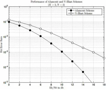
The fundamental diversity rate trade-off between the Alamouti and V-BLAST schemes is illustrated in Figure 1.
Figure 1: Comparison of conventional Alamouti and V-BLAST schemes
Figure 2: Comparison of Alamouti-BLAST and V-BLAST schemes
As illustrated in Figure 2, it can be observed that the performance of the V-BLAST scheme achieves significant diversity gain as the antennas grow in size and the curve comes closer to the Alamouti-BLAST scheme for large antenna system.
Figure 3: Comparison of Alamouti-BLAST and Space-Overlapped Alamouti-BLASTschemes
Figure 3 shows that the curve tends to come closer to the Alamouti-BLAST scheme with the overlapping of Alamouti codes in space.
The performance of the Space and Time Overlapped Alamouti-BLAST scheme illustrated in Figure 4 shows the significant improvement as the curve tends to cross the gain of the Alamouti-BLAST scheme.
V.CONCLUSION
The approach for a simple Massive MIMO scheme based on the overlap of space time codes is proposed. By overlapping the Alamouti codes in spatial dimension and decoding them with the MMSE-BLAST decoder, it is possible to achieve better gain in terms of diversity and multiplexing. The overlapping strategy proposed in space and time with better results, when implemented with more generic space time code constructions can be considered as a very simple and efficient method in order to scale the Massive MIMO systems.
REFERENCES
[1] F.Rusek, D. Persson, B.K Lau, and E. Larsson, “Scaling up MIMO: Opportunities and Challenges with Very Large Arrays”, IEEE Signal Processing Magazine, vol.30, pp. 40-60, January 2013.
[2] T.L Marzetta, “Massive MIMO: An Introduction”, Bell Labs Technical Journal, vol. 20, pp. 11-22, March 2015.
[3] E. Larsson, O. Edfors, F. Tufvesson, and T. Marzetta, “ Massive MIMO for nect generation Wireless Systems”, IEEE Communications Magazine, vol. 52, pp. 186-195, February 2014.
[4] H.Q Ngo, E.G Larsson and T.L. Marzetta, “Energy and Spectral Efficiency of Very Large Multiuser MIMO Systems”, IEEE Transactions on Communications, vol. 61, pp. 1436-1449, February 2013.
[5] Puglielli, N. Narevsky, P. Lu and T. Courtade, “A Scalable Massive MIMO Array Architecture Based on Common Modules”, International Conference on Communication Workshop, pp. 1310-1315, June 2015.
[6] Song, N. Kim and H. Park, “A Binary Space-Time Code for MIMO Systems”, IEEE Transactions on Wireless Communications, vol. 11, pp. 1350-1357, February 2012.
[7] V. Tarokh, H. Jafarkhani and A. R. Calderbank, “Space-Time Block Codes from Orthogonal Designs”, IEEE Transactions on Information Theory, vol. 45, pp. 1456-1467, July 1999.
[8] M. Kalaivani and N. Ramkumar, “A High-Rate Transmit Diversity Technique for Wireless Communication”, International Conference on Communication and Signal Processing, pp. 095-099, April 2014.
[9] S.M. Alamouti, “A Simple Transmit Diversity Technique for Wireless Communications”, IEEE Journal on Select Areas in Communication, vol. 11, pp. 1451-1458, October 1998.
[10] P. Wolniansky, G. Foschini, G. Golden and R. Valenzuela, “V-BLAST: An Architecture for Realizing Very High Data Rates Over the Rich-Scattering Wireless Channel”, International Symposium on Signals, Systems and Electronics, pp. 295-300, October 1998.
[11] D. Tse, P. Viswanath and L. Zheng, “Diversity-Multiplexing tradeoff in Multiple Access Channel”, IEEE Transactions on Information Theory, vol.50, pp. 1859-1874, September 2004.
[12] L. Zhang, S. Li, H. Zheng and M. Wu, “Alamouti Code Assisted V-BLAST (ACAV): A New Space-Time Architecture”, International Conference on Communication Technology, pp. 1-4, November 2006.
[13] P.V. Bien and P.T. Son, “Full Diversity Space-Time Block Coding for Linear Receivers with Low Peak-to-Average Ratio”, International Conference on Advanced Technologies for Communication, pp. 269-273, October 2012.
[14] S. Sezginer, H. Hari and E. Biglieri, “A Comparison of Full-Rate Full-Diversity 2x2 Space-Time Codes for WiMAX Systems”, International Symposium on Spread Spectrum Techniques and Applications, pp. 97-102, August 2008.
[15] D. Wubben, R.Bohnke, V. Kuhn and K. Kammayer, “MMSE Extension of V-BLAST based on Sorted QR Decomposition”, vol.1, pp. 508-512, October 2003.