University of Huddersfield Repository
Liu, Dezheng, Xu, Qiang, Lu, Zhongyu, Xu, Dong Lai and Tan, Feng
The Development of Finite Element Analysis Software for Creep Damage Analysis
Original Citation
Liu, Dezheng, Xu, Qiang, Lu, Zhongyu, Xu, Dong Lai and Tan, Feng (2013) The Development of
Finite Element Analysis Software for Creep Damage Analysis. In: Proceedings of the 2013 World
Congress in Computer Science and Computer Engineering and Application. CSREA Press. ISBN 1
601322380
This version is available at http://eprints.hud.ac.uk/id/eprint/21857/
The University Repository is a digital collection of the research output of the
University, available on Open Access. Copyright and Moral Rights for the items
on this site are retained by the individual author and/or other copyright owners.
Users may access full items free of charge; copies of full text items generally
can be reproduced, displayed or performed and given to third parties in any
format or medium for personal research or study, educational or notforprofit
purposes without prior permission or charge, provided:
•
The authors, title and full bibliographic details is credited in any copy;
•
A hyperlink and/or URL is included for the original metadata page; and
•
The content is not changed in any way.
For more information, including our policy and submission procedure, please
contact the Repository Team at: [email protected].
University of Huddersfield Repository
Liu, De Zheng
The development of finite element analysis software for creep damage analysis
Original Citation
Liu, De Zheng (2013) The development of finite element analysis software for creep damage
analysis. In: Int'l Conf. Scientific Computing | CSC'13 |.
This version is available at http://eprints.hud.ac.uk/21764/
The University Repository is a digital collection of the research output of the
University, available on Open Access. Copyright and Moral Rights for the items
on this site are retained by the individual author and/or other copyright owners.
Users may access full items free of charge; copies of full text items generally
can be reproduced, displayed or performed and given to third parties in any
format or medium for personal research or study, educational or not-for-profit
purposes without prior permission or charge, provided:
•
The authors, title and full bibliographic details is credited in any copy;
•
A hyperlink and/or URL is included for the original metadata page; and
•
The content is not changed in any way.
For more information, including our policy and submission procedure, please
contact the Repository Team at: [email protected].
Abstract - The development and application of computational creep damage is very active among research community and high temperature industry. This paper presents a development and preliminary validation of in-house finite element analysis software for creep damage analysis. The Fortran 90 and existing finite element library were adopted and used in the software development. The validation case study
was conducted and reported, using uni-axial creep case.
Keywords: Computational Creep Damage Mechanics; FE Algorithm; Non-linear Material; Validation
1
Introduction
This paper reports a development and preliminary validation of in-house finite element software for creep damage analysis. Creep damage mechanics has been developed and applied for the analysis of creep deformation and the simulation for the creep damage evolution and rupture of high temperature components [1]. The computational capability relies on the availability of a computational tool and a set of creep damage constitutive equations which can accurately depicts the complex phenomena. This paper addresses the former.
The need of such computational capability and the justification for developing in-house software was conducted and reported in the early stage of this research [2, 3]. Essentially, the creep damage problem is of time dependent, non-linear material behavior, and multi-material zones. The standard software does not provide the computational capability to simulate the tertiary creep stage readily without the development of complicated material user subroutine. The computational capability can only be obtained by either the development and use of special subroutine in junction with standard commercial software such as ABAQUS and ANSYS or the development and use of dedicated in-house software, each has its own advantages and disadvantages [2].Hyde [4] and Hayhurst [5] have reported the development and the use of their in-house software for creep damage analysis; furthermore, Ling has presented a detailed discussion and use of Runge-Kutta type integration algorithm [6]. On the other hand, it is noted that Xu revealed the deficiency of KRH formulation and proposed a new formulation for the multi-axial generalization in the development of creep damage constitutive equations [7]. The new creep damage constitutive equations for low Cr-Mo steel and for high Cr-Mo steel are under developing by colleagues in this research group [8, 9].
The purpose of this paper is to present the finite element method based on CDM to design FE software for creep damage mechanics. More specifically, it reports the structure of the new FE software and the existing FE library applied in obtaining such computational tool via an approach for stress and field variable updating, and preliminary validation of current version of such software via a uni-axial tension model. The contribution of this paper is to provide a new version of in-house software to solve the whole process of all the three stages of creep deformation and damage problem.
2
The finite element method based on
CDM
2.1
The Continuum Damage Mechanics (CDM)
The continuum damage mechanics (CDM) used the concept of creep damage as internal variable [10, 11, 12]. One of the features of CDM is phenomenological and the damage parameter can in this context represent creep damage. In creep damage mechanics, the material gets damaged does not essential has to be understood in detail and the damage should be considered in analysis [13].
The creep deformation is typically divided into primary, secondary and tertiary stages. Initially, the characteristics of the primary-secondary (steady state) creep deformation behavior are observed by simple experiments, but later the mathematical description of tertiary creep through the use of CDM.
The finite element technique combined with continuum damage mechanics has been testified to be an efficient tool in assessing the performance of the structural components [14-16]. In many commercial finite element packages, the user-routines can be written for implemented taking into account one or more damage mechanisms [17].
Rupture processes can also be investigated by use of CDM approach [18]. Some investigations of creep crack initiation and growth in notched specimens have been performed with promising results [19, 20].
2.2
The general structure of the finite element
software
The structure of developing in-house finite element software for creep damage analysis is listed in Figure 1.
D. Liu
1, Q. Xu
1, Z. Lu
2, D. Xu
1, F. Tan
11School of Science and Engineering, Teesside University, Middlesbrough, TS1 3BA, UK 2School of Computing and Engineering, University of Huddersfield, Huddersfield, HD1 3DA, UK
Fig. 1. The flow diagram of the structure of the new finite element software
The steps for the development of finite element software can be summarized in:
1. Input the definition of a specific FE model including nodes, element, material property, boundary condition, as well as the computational control parameters
2. Calculate the initial elastic stress and strain
3. Integrate the constitutive equation and update the field variables such as creep strain, damage, stress; the time step is controlled
4. Remove the failed element [21] and update the stiffness matrix
5. Stop execution and output results
2.3
The integration of creep damage constitutive
equation
The FEA solution critically depends on the selection of the size of time steps associated with an appropriate integration method. Some integration method has been reviewed in previous work [3]. In the current version, Euler forward integration subroutine, developed by colleague [22], was adopted here for simplicity. More sophisticated Runge-Kutta type integration scheme will be adopted and explored in future.
2.4
The finite element algorithm for updating
stress
The Absolute Method [23] has been given for the solution of the structural creep damage problems. The principle of virtual work applied to the boundary value problem is given:
Pload= [Kv] * TOTD – P c (1)
Where Pload is applied force vector, and [Kv] is the global
stiffness matrix, which is assembled by the element stiffness matrices [Km]; TOTD is the global vector of the nodal
displacements and P c is the global creep force vector.
[Km] = ∫∫ [B] T [D] [B] dxdy (2)
The [B] and [D] represent the strain-displacement and the stress-strain matrices respectively.
TOTD = [Kv] -1* (Pload + P c) (3)
The initial P c is zero and the Choleski Method [14] is used
for the inverse of the global stiffness matrix [Kv]. By giving the
Pload, the elastic strain εek and the elastic stress σek for each
element can be obtained:
εek= [B] * ELD (4)
σek = [D] * εek (5)
The element node displacement ELD can be found from the global displacement vector and the creep strain rate εckrate
for each element can be obtained by substituting the element elastic stress into the creep damage constitutive equations. The creep strain can be calculated:
εck ( t + △t ) = εcK( t ) + εcKrate*△t (6)
The node creep force vectors for each element are given by:
Pck = [B] T [D] * εcK (7)
The node creep force vector Pck can be assembled into the
global creep force vector P c and the P c is used to up-date
equation (1). Thus, the elastic strain can be updated:
εtotk= [B] * ELD = εek+ εck (8)
εek= [B] * ELD – εck (9)
Where the εtotk and εck are represent the total strain and
creep strain for each element respectively; and the elastic strain
εek is used to up-date the equation (5).
3
The application of existing finite
element library
3.1
The finite element meshing
The existing subroutines [23] are available in performing the mesh of element for the triangles, quadrilaterals and hexahedra “bricks”. For example, the subroutine geometry_3tx (iel, nxe, aa, bb, coord, num) can form the coordinates and node vector for a rectangular mesh of uniform 3-node triangles. More specifically, it is counting in the x-direction and local numbering clockwise. For the quadrilateral elements and the hexahedra “bricks” elements, the subroutine geometry_4qx and the subroutine geometry_8bxz are also available in [23].
3.2
The element stiffness matrix assembly
The special purpose subroutines such as subroutine formnf, subroutine formkb, subroutine formku, and subroutine fsparv can assembly the individual element matrices to form the global matrices. The selection of element stiffness matrix subroutine is according with the definition of the geometrical details, especially in the nodal coordinates of each element and the element’s place in overall node numbering scheme. More details see [23].
3.3
The solution of equilibrium equation for
creep problem
Direct solution methods and iterative solution methods have been used in solving the creep problem [13]. In direct solution method, the subroutine sparin and subroutine spabac based on Cholesky direct solution method are used to solve the sets of linear algebraic equations [23]. In iterative solution method, the subroutine cholin and subroutine chobac based on Jacobi iterative solution methods can be used in programming.
4
Validation of finite element software
and FE model
4.1
The creep constitutive equation
Creep damage constitutive equations are proposed to depict the behaviors of material during creep damage (deformation and rupture) process, especially for predicting the lifetime of materials, within the CDM-based numerical computational tool. Kachanov-Rabatnov-Hayhurst (KRH) constitutive equations [24] are introduced as followed in details and used in current program.
Uni-axial form
{
̇ ) ) ) ) ) ̇ ( ) ̇ ) ̇ ) ) ̇ ̅̇ )
(10)
Where A, B C, h, H* and Kc are material parameters. H (0<H< H*) indicates strain hardening during primary creep, φ (0< φ < 1) describe the evolution of spacing of the carbide precipitates [24].
Multi-axial form
{ ̇
)
) )) )
̇ ) ̇ )
φ̇ φ) ) ̇ ̇ 〈 〉 )
(11)
Where is the Von Mises stress, is the maximum principal stress and is stress state index defining the multi-axial stress rupture criterion [24].
TABLE I.
Numerical values of constitutive parameters at 590 ℃ [25]
Coefficient Value
A (h-1) 2.1618 × 10⁻⁹
B (MPa-1) 2.0524 × 10⁻¹
C (-) 1.8537
h( MPa) 2.4326 × 10⁵
H* (-) 0.5929
Kc (h-1) 9.2273 × 10⁵
The intergranular cavitation damage varies from zero, for the material in the virgin state, to 1/3, when all of the grain boundaries normal to the applied stress have completely cavitated, at which time the material is considered to have failed [25]. Thus, the critical value of creep damage is set to 0.3333333. The time increment is set to 1.0 hour. Once the creep damage reaches the critical value, the program will stop execution and the results will be output automatically.
4.2
Validation
Preliminary validation of such software was performed and it was conducted via a two- dimensional uni-axial tension model given bellow.
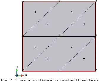
Fig. 2. The uni-axial tension model and boundary conditions
The length of a side is set to 1 meter.
The Young's modulus and Poisson's ratio are set to 1000000 KN/m2 and 0.3 respectively.
A uniformly distributed load 40KN/m was applied on the top line of this uni-axial tension model. The boundary constraint conditions are given in Table II.
TABLE II.
The Numerical boundary constraint
Node number
Constraint in x direction
Constraint in y direction
Load in x direction
Load in y direction
Node No.1 shut open 0 KN/m2 10 KN/m2
Node No.2 open open 0 KN/m2 20 KN/m2
[image:5.612.304.573.191.269.2] [image:5.612.346.513.426.563.2]Node No.4 shut open 0 KN/m2 0 KN/m2
Node No.5 open open 0 KN/m2 0 KN/m2
Node No.6 open open 0 KN/m2 0 KN/m2
Node No.7 shut shut 0 KN/m2 0 KN/m2
Node No.8 open shut 0 KN/m2 0 KN/m2
Node No.9 open shut 0 KN/m2 0 KN/m2
The theoretical stress in Y direction can be found as:
The stress in X direction should be zero.
These stress values should remain the same throughout the creep test up to failure.
Using the theoretical stress value into uni-axial version of creep constitutive equations, the theoretical rupture time, creep strain rate, creep strain and damage can be obtained by a excel program [26] and some of them are shown in Table III.
TABLE III.
The theoretical rupture time, creep strain rate, creep strain and damage obtained by excel program
Rupture time Creep strain rate Creep strain Creep damage
104062 0.000065438 0.179934333 0.33333335
5
FE results and discussion
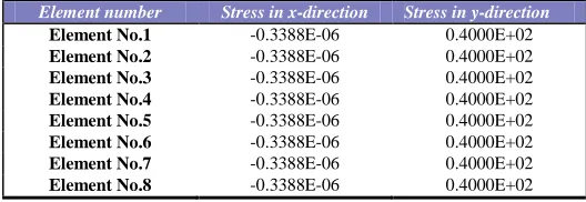
TABLE IV.
The initial elastic stress obtained from FE software
Element number Stress in x-direction Stress in y-direction
Element No.1 -0.3388E-06 0.4000E+02
Element No.2 -0.3388E-06 0.4000E+02
Element No.3 -0.3388E-06 0.4000E+02
Element No.4 -0.3388E-06 0.4000E+02
Element No.5 -0.3388E-06 0.4000E+02
Element No.6 -0.3388E-06 0.4000E+02
Element No.7 -0.3388E-06 0.4000E+02
Element No.8 -0.3388E-06 0.4000E+02
The initial elastic stress and the stress involving creep deformation and stress updating are shown in Table IV and Table V, respectively. Both confirmed the uniform distribution of stresses, and the values of stress in Y direction obtained from FE software are correct, and the stress in X direction is negligible.
TABLE V.
The stress obtained from FE software with the stress update program
Element number Stress in x-direction Stress in y-direction
Element No.1 -0.3388E-06 0.4000E+02
Element No.2 -0.3388E-06 0.4000E+02
Element No.3 -0.3388E-06 0.4000E+02
Element No.4 -0.3388E-06 0.4000E+02
Element No.5 -0.3388E-06 0.4000E+02
Element No.6 -0.3388E-06 0.4000E+02
Element No.7 -0.3388E-06 0.4000E+02
Element No.8 -0.3388E-06 0.4000E+02
TABLE VI.
Rupture time, creep strain rate, creep strain and damage obtained from FE software at failure
Element number
Rupture time
Strain rate Creep strain Creep damage
Element No.1
0.1040E+06 0.6540E-04 0.1798E+00 0.3334E+00
Element No.2
0.1040E+06 0.6540E-04 0.1798E+00 0.3334E+00
Element No.3
0.1040E+06 0.6540E-04 0.1798E+00 0.3334E+00
Element No.4
0.1040E+06 0.6540E-04 0.1798E+00 0.3334E+00
Element No.5
0.1040E+06 0.6540E-04 0.1798E+00 0.3334E+00
Element No.6
0.1040E+06 0.6540E-04 0.1798E+00 0.3334E+00
Element No.7
0.1040E+06 0.6540E-04 0.1798E+00 0.3334E+00
Element No.8
0.1040E+06 0.6540E-04 0.1798E+00 0.3334E+00
TABLE VII.
The percentage error
0.0596%
0.0581%
| | 0.0747%
0.02%
Other results are shown in Tables VI to VII. They show the results obtained from the FE software do agree with the expected theoretical values and the percentage errors are negligible.
In the current version, Euler forward integration subroutine, developed by colleague [22] was adopted here. Rupture time, strain rate, creep strain and damage obtained from FE software have been revealed that have a good agreement with the theoretical values obtained from the excel program. Work is ongoing in this area and will be reported in future
6
Conclusion
This paper reports the finite element method based on CDM to design FE software for creep damage mechanics. It presents the structure of the new FE software and the use of existing FE library in obtaining such computational tool via an approach for stress and field variable updating. It further investigates preliminary validation of current version of such software via a uni-axial tension model.
The immediate future development work includes: 1) multi-materials; 2) implementing R-K integration scheme; 3) intelligent and practical control of time step; 4) removal of failed element and update stiffness matrix; and 5) further validation.
7
Reference
[image:6.612.40.304.557.648.2][2] D. Liu, Q. Xu and Z. Lu, “The review of computational FE software for creep damage mechanics,” Advanced Materials Research, vol. 510, pp. 495-499, 2012. [3] D. Liu, Q. Xu and Z. Lu, “Research in the development of computational FE software for creep damage mechanics,”18th International Conference on Automation and Computing (ICAC),Loughborough University, Leicestershire, 8th September 2012.
[4] FE-DAMAGE User’s Manual, 1st ed., University of
Nottingham, Nottingham, UK, 1994.
[5] D. R., Hayhurst and A. J., Krzeczkowski, “Numerical solution of creep problems”, Compute. Methods App. Mech. Eng., vol. 20, pp.151-171 (1979).
[6] X. Ling, S. T. Tu and J. M. Gong, “Application of Runge-Kutta-Merson algorithm for creep damage analysis”,
International Journal of Pressure Vessels and Piping, vol. 77,
pp. 243-248, 2000.
[7] Q. Xu, “Creep damage constitutive equations for multi-axial states of stress for 0.5Cr0.5Mo0.25V ferritic steel at 590°C”, Theoretical and Applied Fracture Mechanics, vol. 36, pp. 99-107, 2001.
[8] Q. H. Xu, Q. Xu, Y.X. Pan and M. Short, “Current state of developing creep damage constitutive equation for 0.5Cr0.5Mo0.25V ferritic steel”, Advanced Materials
Research, vol. 510, pp. 812-816, 2012.
[9] L. An, Q. Xu, D. Xu and Z. Lu, “Review on the Current State of Developing of Advanced Creep Damage Constitutive Equations for High Chromium Alloy”, Advanced
Materials Research, vol. 510, pp. 776-780, 2012.
[10] L.M. Kachanov, “On the rupture time under the condition of creep”, Izv. Akad. Nauk SSSR, Otd. Tekh. Nauk, Vol. 8, pp. 26-31, 1958.
[11] Y.N. Rabotnov, “Creep problems in structural members”, North-Holland, 1969.
[12] S. Murakami, “Notion of continuum damage
mechanics and its application to anisotropic creep damage theory”, ASME J. Eng. Mater. Technol., Vol. 105, pp. 99-105, 1983.
[13] E. J. Barbero, P. Lonetti and K. Sikkil, “Finite Element Continuum Damage Modeling of Plain Weave Reinforced Composites”, Composites part B, vol. 37, pp. 137-147, 2006.
[14] F.R. Hall and D.R. Hayhurst, “Continuum damage mechanics modeling of high temperature deformation and failure in a pipe weldment”, Proc. R. Soc. Lond. A, Vol. 433, pp. 383-403, 1994.
[15] D.R. Hayhurst, “High-temperature design and life assessment of structures using continuum damage mechanics”,
Sixth Int. Conf. on Creep and Fatigue, London: IMechE
Conference Transaction, pp. 103-121, 1996.
[16] T.H. Hyde, W. Sun and A. A. Becker, “Creep crack growth in welds: a damage mechanics approach to predicting initiation and growth of circumferential cracks”, International Journal of Pressure Vessels and Piping, Vol. 78(11-12), pp. 765-771, 2000.
[17] H.T. Yao, F.Z. Xuan, Z.D. Wang and S.T. Tu, “A review of creep analysis and design under multi-axial stress states”, Nuclear Engineering and Design, Vol. 237(18), pp. 1969-1986, 2007.
[18] S. Peter, “Numerical simulation of weldment creep response”, PhD Thesis, Department of Materials Science and Engineering, Royal Institute of Technology (KTH), Sweden, 2002.
[19] H. Riedel, “Creep crack growth under small-scale creep conditions”, Int. J. of Fracture, Vol. 42, pp. 173-188, 1990.
[20] S. Murakami and Y. Liu, “Mesh-dependence in local approach to creep fracture”, Int. J. Damage Mechanics, Vol. 4, pp. 230-250, 1995.
[21] M.T. Wong, “Three-Dimensional Finite Element Analysis of Creep Continuum Damage Growth and Failure in Weldments”, PHD thesis, University of Manchester, UK, 1999. [22] F. Tan, Q. Xu, Z. Lu and D. Xu, “The preliminary development of computational software system for creep damage analysis in weldment”, Proceedings of the 18th International Conference on Automation & Computing, Loughborough University, Leicestershire, UK, 8 September 2012.
[23] I.M. Smith and D.V. Griffiths, “Programming the Finite Element Method”, John Wiley & Sons Ltd., 4th ed. Sussex, 2004.
[24] D. R., Hayhurst, P. R. Dimmer and G. J. Morrison, “Development of continuum damage in the creep rupture of notched bars”, Trans R Soc London A, vol. 311, pp. 103–129, 1984
[25] I.J. Perrin and D.R. Hayhurst, “Creep constitutive equations for a 0.5Cr–0.5Mo–0.25V ferritic steel in the temperature range 600–675 ◦C”, J. Strain Anal. Eng, Vol. 31, 299–314.1996.