This is an
Accepted Manuscript
, which has been through the
Royal Society of Chemistry peer review process and has been
accepted for publication.
Accepted Manuscripts
are published online shortly after
acceptance, before technical editing, formatting and proof reading.
Using this free service, authors can make their results available
to the community, in citable form, before we publish the edited
article. We will replace this
Accepted Manuscript
with the edited
and formatted
Advance Article
as soon as it is available.
You can find more information about
Accepted Manuscripts
in the
Information for Authors.
Please note that technical editing may introduce minor changes
to the text and/or graphics, which may alter content. The journal’s
standard Terms & Conditions and the Ethical guidelines still
apply. In no event shall the Royal Society of Chemistry be held
responsible for any errors or omissions in this
Accepted Manuscript
or any consequences arising from the use of any information it
contains.
Accepted Manuscript
Journal of
Materials Chemistry A
This article can be cited before page numbers have been issued, to do this please use: A. Sinha, D. Miller
Journal of Materials Chemistry A
ARTICLE
Received 00th January 20xx, Accepted 00th January 20xx
DOI: 10.1039/x0xx00000x
www.rsc.org/
Development of Novel Anode material for Intermediate
Temperature SOFC (IT-SOFC)
Amit Sinha,
a,bDavid N. Miller,
aand John T.S. Irvine
aSolid oxide fuel cells (SOFC) offer a clean technology to electrochemically generate electricity and heat from hydrogen or hydrocarbon based fuel at high efficiencies. All the active components of the SOFC unit cell comprise of rare-earth or low abundant elements. An increase in the cost of rare-earths is likely to jeopardize the commercialization prospects of SOFC based technologies. Hence, a greater scientific effort should be focused on the development of rare-earth free SOFC materials. The previous research works on electrode-supported intermediate temperature solid oxide fuel cells (IT-SOFCs) indicate that the anode supported concept provides better electro-chemical performance than the cathode supported one. Therefore, the total material cost of anode-supported SOFC is largely governed by the cost of the anode material. The objective of the present investigation was, therefore, the development of a rare-earth free anode material for IT-SOFC. The present work envisages application of titanium oxycarbide as a possible rare-earth free anode material for intermediate temperature solid oxide fuel cells. Titanium oxycarbide samples (TiOxC1-x with x = 0.2 - 0.8) were prepared by
reaction-sintering of TiO and TiC powders under vacuum at 1500 °C for 5 h. Basic studies on TiOxC1-x (x = 0.2-0.8)
with respect to phase purity and stability under oxidizing and reducing environments were carried out. The compatibility of titanium oxycarbide with intermediate-temperature electrolyte material (Ce0.9Gd0.1O3-δ) was
studied. The electrochemical properties of planar cells using Ce0.9Gd0.1O3-δ as electrolyte and employing TiO0.2C0.8
and La0.8Sr0.2Co0.2Fe0.8O3-δ based anode and cathode materials were investigated. The present study indicates that
titanium oxycarbide is an alternative anode material for IT-SOFC. This is the first report on the possibility of application of a rare-earth free ceramic in the form of titanium oxycarbide as a potential fuel electrode in IT-SOFC.
1 Introduction
SOFCs offer a clean, low pollution technology to
electrochemically generate electricity and heat from hydrogen or hydrocarbon based fuel at high efficiencies. Their efficiencies are not limited by the concept of Carnot cycle. Beside the high efficiency, SOFC promises many advantages over traditional energy conversion systems that include reliability, modularity, fuel flexibility and very low levels of greenhouse gas emissions and hence these cells have emerged as one of the most promising technologies for the power sources of future. The greatest challenge in SOFC technology is to reduce the operating temperature and thereby achieve stability, reliability and reduced capital and operating cost. Reduction of operating temperature of SOFC is associated with
reduced catalytic activities of electrode materials along with decrease in ionic conductivity of electrolyte material. The problem of reduced ionic conductivity of electrolyte material can be circumvented by reducing the electrolyte thickness in the fuel cell, which in turn leads to electrode-supported SOFC concepts rather than the electrolyte-supported one. The
majority of research works on electrode-supported
intermediate temperature solid oxide fuel cells (IT-SOFCs) that
are operative in the temperature range of 600–800 °C,
indicate that the anode supported concept provides better electro-chemical performance than the cathode supported
one.1-4 Furthermore, the anode support is physically and
chemically more compatible with oxide electrolytes than the cathode support under sintering conditions. Therefore, the total material cost of anode supported SOFC unit cell is largely governed by the cost of anode material.
The most common anode material for SOFC is based on the nickel–yttria stabilized zirconia (Ni-YSZ) cermet which exhibits superior catalytic properties for fuel oxidation and good current collection. However, Ni-YSZ based anodes have several functional limitations with respect to sulphur poisoning, coking, lack of redox stability and agglomeration of nickel particles with time that lead to degradation of electrochemical
Journal
of
Materials
Chemistry
A
Accepted
Manuscript
ARTICLE
Journal Name
performance of SOFC.5-9 The weaknesses of the nickel cermet
based anode under operating conditions prompted large scale research on the development of novel oxide ceramic based anode materials.10-16 It may be noted that most of the anode materials developed so far are based on structures containing rare-earth elements. In fact, all the active components of the SOFC unit cell comprise of rare-earth or low abundant elements. The cost of rare-earth elements in the form of oxides or other inorganic salts not only depends on the production cost but also heavily influenced by the industrial/economic policies of rare-earth producing states since rare earths are considered as one of the strategic materials for clean-energy and defence related technologies. An increase in the cost of rare-earths, in near future, may jeopardize the commercialization prospects of SOFC based technologies due to the higher cost and/or non-availability of rare earth compounds. Hence, a greater scientific effort should be focused on the development of rare-earth free SOFC materials.
The aim of the present investigation was, therefore, the development of rare-earth free anode material for IT-SOFC. The previous work in our laboratory indicated that titanium oxycarbide based material possesses a very high electronic
conductivity.17 Hence, a titanium oxycarbide based system was
selected in this study as a candidate rare-earth free electrode material for IT-SOFC.
Titanium oxycarbide attracts significant technological interests as it exhibits a combination of metallic and covalent/ionic character which is reflected by its physical properties like high electronic conductivity, high melting point, high hardness
etc.18 Fundamentally, the existence of covalent characteristics
in titanium oxycarbide originates from strong overlap of
anionic O(C) 2p orbital with d electrons of transition metal (Ti)
while the metallic character stems from high occupation of Ti
3d bands close to Fermi level. Titanium oxycarbide may be
visualized as a solid solution of titanium carbide (TiC) and titanium monoxide (TiO) and usually represented as TiOxC1-x,
where 0≤x≤1, having the same face-centred cubic (FCC) rock-salt structure of TiC.
In the present study, TiOxC1-x powders were prepared by solid
state reaction of TiC and TiO as this process has been found to yield more phase-pure oxycarbide than that can be produced
by carbothermal reduction of TiO2..
19
Solid state reaction of TiC and TiO is essentially associated with more homogeneous diffusion that takes place during reaction-sintering of TiC-TiO mixture at elevated temperatures.
In the present investigation, we present the basic studies on TiOxC1-x (with x = 0.2, 0.5 and 0.8) with respect to phase purity, stability under oxidizing as well as reducing environments, and electrochemical properties of electrolyte supported planar cell using gadolina-doped ceria (GDC, Ce0.9Gd0.1O3-δ) electrolyte
and employing TiO0.2C0.8 and La0.8Sr0.2Co0.2Fe0.8O3-δ (LSCF)
based anode and cathode materials respectively. Here δ
represents the extent of non-stioichiometry present in the oxide due to the presence of aliovalent dopant(s) in the host matrix.
2 Experimental
Three different compositions of titanium oxycarbide powders
(TiOxC1-x with x = 0.2, 0.5 and 0.8) were prepared by solid state
reaction of titanium carbide (TiC) and titanium monoxide (TiO). TiC (Alpha Aesar, 99.9% purity, av. particle size:- 2 µm) and TiO (Aldrich, 99.5 % purity; -325 mesh size) powders were mixed according to stoichiometric ratios in a planetary ball mill (Fritsch Pulverisette 7) under acetone media using zirconia balls. The powder mixtures were dried under ambient conditions and subsequently compacted into green pellets of 14 mm diameter using a uniaxial hydraulic press at a pressure of 150 MPa. The green compacts were reaction-sintered under
vacuum (Torvac) at a temperature of 1500 °C for 5 h.
The phase purity of the starting materials and reaction-sintered oxycarbide samples was studied through X-ray
diffraction (XRD) using CuKα radiation (PANalytical
X’accelerator). The lattice parameters of titanium oxycarbide powders were determined using Rietveld refinement of the XRD data. Rietveld analysis was performed using Fullprof
program incorporated in the WinPLOTR software package.20
The analysis was accomplished assuming Fm-3m space group
for rock-salt structure. In the present study, a Thomson-Cox-Hasting pseudo-Voigt peak profile function was used for the profile fitting and the background was fitted with a sixth order
polynomial function.21
The microstructures of the fractured surfaces of the
reaction-sintered TiOxC1-x samples were studied using scanning electron
microscopy (SEM, JEOL JSM-5600) along with energy dispersive X-ray spectroscopy (EDS, OXFORD INCA Energy 200). The
morphology of the TiOxC1-x powders obtained after grinding
the sintered compacts were also studied through SEM as well as by transmission electron microscopy (TEM, JEOL JEM-2011).
To study the stability of TiOxC1-x powders under oxidising
environment, thermo-gravimetric analysis (TGA) experiments
on TiOxC1-x powders were performed in a thermo-gravimetric
analyser (NETZSCH TG 209) under flowing air from ambient
temperature to 900 oC at a heating rate of 5 K/min. The
powder samples were kept on alumina crucible during TGA experiments. The stability of TiOxC1-x samples under reducing
environment was investigated by subjecting the TiOxC1-x
powders to a prolonged heat treatment under Ar+5%H2
environment at 900 °C for 18 h followed by analysis of phases
of the heat treated samples through XRD.
To study the interaction of titanium oxycarbide with GDC
based electrolyte, TiO0.2C0.8 powder was mixed with GDC
powder (Ce0.9Gd0.1O3-δ , PRAXAIR, 99.9% purity, av. particle
size:- 1.2 µm) in equal weight ratio and compacted into green compacts of 14 mm diameter using a hydraulic press under
Journal
of
Materials
Chemistry
A
Accepted
Manuscript
Published on 21 June 2016. Downloaded by University of St Andrews Library on 23/06/2016 09:48:12.
150 MPa pressure. The compact was subjected to a
heat-treatment at 900 °C for 18 h under flowing Ar+5%H2 gas. After
the heat treatment, analysis of the phases was carried out through XRD.
Thermal expansion coefficient (TEC) of titanium oxycarbide
sample (TiO0.2C0.8) was measured between 100 – 950 oC using
a horizontal dilatometer (Netzsch DIL 402C) in flowing Ar-
5%H2 environment with a constant heating/cooling rate of
3 K/min. For utilisation of titanium oxycarbide as anode
material, TiO0.2C0.8 powder was mixed with GDC powder (1:1
by wt.) and a terpineol based ink was prepared. Similarly, an ink of cathode material was prepared using a mixture of La0.8Sr0.2Co0.2Fe0.8O3-δ (LSCF, PRAXAIR) powder and GDC
powder (1:1 by wt.) in terpineol based vehicle. GDC based electrolyte supported button cells were fabricated in two stages. In the first stage, the bilayer of electrolyte-anode
half-cell was fabricated by sintering GDC green compact at 1400 oC
for 4 h to produce an electrolyte having a thickness of 510 µm and diameter of 20 mm followed by painting of anode ink on one surface of the electrolyte and subsequently firing the
bilayer at 1000 oC for 1 h under Ar+5%H2 environment. The
electrolyte-anode bilayer was sealed onto an alumina fuel cell test fixture using ceramic cement (Ceramabond 552VFG, Aremco). LSCF based cathode was brush painted on the
electrolyte surface and fired in-situ at 900 oC for 1 h in the fuel
cell test setup after sealing the anode compartment. During this process, the anode compartment was purged with
Ar+5%H2 gas in order to protect the anode material. To
complete the cell, silver mesh/wire and silver paste were used for current collection. The electrochemical characterization of the button cell was conducted with humidified hydrogen (3%
H2O) as fuel and ambient air as oxidant. The open circuit
voltage of the cell was recorded in the temperature range of
400–800 oC and the current–voltage (I-V) measurements were
made at 500, 600 and 700 oC utilizing a SOLARTRON
electrochemical test station. A constant fuel flow rate of 70
ml.min-1 was used during the measurements. During the
electrochemical characterisation, impedance spectra were recorded under open circuit voltage (OCV) conditions using a Solatron 1260 frequency response analyser coupled with a 1287 electrochemical interface within a frequency range of 1Mz to 0.1Hz with an applied ac voltage of amplitude 10mV. The data collected was analysed using a commercial software (Z-View, Scribner Associates).
3 Results and discussion
Fig. 1a-c show the XRD patterns of TiOxC1-x powders with x = 0.2, 0.5 and 0.8 respectively. All the patterns exhibit phase pure titanium oxycarbide and can be indexed to cubic rocksalt
structure in Fm-3m space group (No 225). Absence of any
un-indexed reflection in the XRD patterns suggests the phase purity of the powders. The XRD patterns were refined through Rietveld analysis to determine the lattice parameters of the
Fig. 1 XRD patterns of TiOxC1-x powders with (a) x = 0.2; (b)
x = 0.5 and (c) x = 0.8 respectively
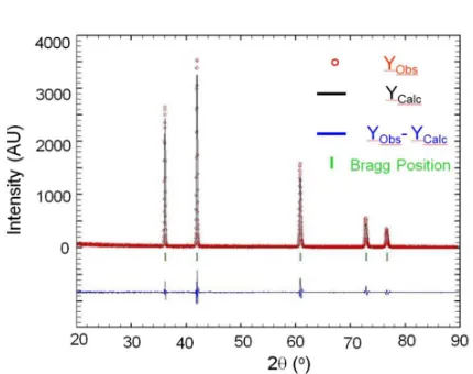
oxycarbide powders. Fig. 2 shows the Rietveld pattern of
TiO0.5C0.5 powder. The tick marks below the patterns represent
the positions of all possible Bragg reflections. The lower solid line represents the difference between the observed and calculated intensities. The quality of the agreement between observed and calculated profiles is evaluated by profile factor (Rp), weighted profile factor (Rwp), expected weighted profile
factor (Rexp), and reduced chi-square (χ
2). The mathematical
expressions of the above parameters can be found elsewhere.20 For TiO0.5C0.5 powder, the values of Rp, Rwp, Rexp
and χ2 were 11.4, 13.8, 9.73, 2.019 respectively. The values of the reliability parameters guarantee the reliability of
refinements. The calculated lattice parameter of TiO0.5C0.5
powder prepared by solid state reaction of TiO and TiC is 4.30569(8) Å which is close to the reported value of lattice
parameter of titanium oxycarbide of similar composition.22
Fig. 2 Rietveld pattern of TiO0.5C0.5 powder. The tick marks below
the patterns represent the positions of all possible Bragg reflections. The lower solid line represents the difference between the observed and calculated intensities
10 20 30 40 50 60 70 80 90
In te n s it y ( A .U .)
2θ (o)
(2 2 2 ) (3 1 1 ) (2 2 0 ) (2 0 (1 1 1 ) (a) (b) (c)
Journal
of
Materials
Chemistry
A
Accepted
Manuscript
[image:4.612.321.552.42.231.2] [image:4.612.324.539.284.454.2]ARTICLE
Journal Name
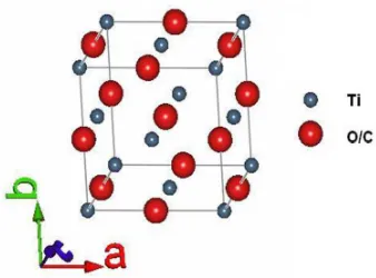
[image:5.612.345.514.71.196.2]Based on the refined structural parameters obtained through Rietveld analysis, the unit cell structure of titanium oxycarbide could be visualised using FpStudio program of Fullprof Suit.20 Fig. 3 illustrates the unit cell of TiO0.5C0.5 which is having a FCC structure with B1 symmetry. The lattice parameters of TiO0.2C0.8 and TiO0.8C0.2 powders were similarly calculated and were found to be close to that of reported values.
Fig. 3 The unit cell of titanium oxycarbide (TiO0.5C0.5)
Fig. 4 XRD patterns of (a) as synthesized TiO0.2C0.8 powder and
(b) the powder obtained after heat treatment at 900 °C for 18 h
in Ar+5% H2
Fig. 5 Thermo-gravimetric (TG) plots of titanium oxycarbide powders under flowing air
Fig. 6 SEM photo micrographs of fracture surfaces of reaction sintered TiOxC1-xspecimens with (a) x = 0.2; (b) x = 0.5 and (c) x = 0.8
respectively
20 30 40 50 60 70 80 90
TiO0.2C0.8
(b)
(a)
In
te
n
s
it
y
(
A
.U
.)
2θ(o)
(a)
(b)
(c)
10 µm
Journal
of
Materials
Chemistry
A
Accepted
Manuscript
Published on 21 June 2016. Downloaded by University of St Andrews Library on 23/06/2016 09:48:12.
[image:5.612.157.531.283.470.2] [image:5.612.73.543.515.637.2]Journal of Materials Chemistry A
ARTICLE
Fig. 4 shows the XRD pattern of TiO0.2C0.8 powder heat treated at
900 oC for 18 h under Ar+5%H2 environment (Fig. 4b). The pattern is
similar to the pattern of the starting powder (Fig. 4a) which
suggests that TiO0.2C0.8 powder is stable under reducing
environment at 900 oC. A slight shift of the XRD peaks to lower angle is observed for titanium oxycarbide sample after thermal treatment in reducing environment at 900 oC as compared to that of the as-produced oxycarbide powder. The slight shift of XRD peaks is due to a little increase in the lattice parameter of the oxycarbide unit cell which may be attributed to formation of point defects in the structure of the heat treated sample. Similar heat treatments under reducing environment at 900 oCwere provided to TiO0.5C0.5
and TiO0.8C0.2 powders and the XRD patterns after heat treatments
were found to be similar with that of the starting powder and hence indicated their stability under reducing conditions.
Fig. 5 shows the thermo-gravimetric (TG) plots of TiOxC1-x
powders under flowing air environment between room temperature to 900 oC at a heating rate of 5 K/min. It can be observed from the TG plots that onset of non-isothermal oxidation of TiOxC1-x powders takes place at a temperature
above 350oC. The corresponding differential thermogravi-
metric (DTG) plots indicate two stage oxidation for TiO0.2C0.8
and TiO0.5C0.5 powders – the first stage corresponds to rapid
oxidation that contributes to more than 60% of the weight gain which takes place between 400 to 600 oC having a peak
temperature of 550oC while the second stage corresponds to
slow oxidation taking place from 600 – 900 oC. For TiO0.2C0.8
powder, a weight gain of less than 20 % takes place below 600
oC and rest of the oxidation takes place at higher
temperatures. The above results suggests that the mode of non-isothermal oxidation of titanium oxycarbide powders depends on the carbon content in the powder while the onset temperature of oxidation has been found to be independent of carbon content.
The SEM photomicrographs of fracture surfaces of reaction sintered titanium oxycarbides are shown in Fig. 6a-c. It can be observed that the microstructures are porous and uniform exhibiting partially sintered grains. The average grain sizes of reaction-sintered oxycarbide samples have been found to increase with increase in oxygen content of TiOxC1-x. This may
be attributed to the relative difference of melting points of TiC
and TiO (3160 and 1750 °C respectively) with
reaction-sintering temperature (1773 K) being much higher than 0.5Tm
(where Tm is the melting point in Kelvin) particularly for oxygen
rich sample which leads to grain growth during sintering process.
Fig. 8 (a) TEM photomicrograph of TiO0.2C0.8 powder along
with its (b) SAED pattern with their corresponding crystal planes
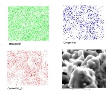
Fig. 7 shows the elemental mapping and corresponding secondary electron (SE) image of TiO0.2C0.8. The X-ray maps
exhibit the uniform distribution of constituent elements. This corroborates the result of XRD analysis about the phase purity
of the oxycarbide sample. The TEM micrograph of TiO0.2C0.8
powder is shown in Fig. 8a. The selected area electron diffraction (SAED) pattern of the powder with corresponding
crystal planes is shown in Fig. 8b which suggests the
polycrystalline single phase TiO0.2C0.8 without impurity phases.
The ring intensities suggest the crystallinity of the polycrystalline oxycarbide powder.
Fig. 7 EDS X-ray mapping of reaction-sintered TiO0.2C0.8
specimen
(b)
(a)
Journal
of
Materials
Chemistry
A
Accepted
Manuscript
[image:6.612.333.515.166.324.2] [image:6.612.324.547.396.507.2]ARTICLE
Journal Name
Fig. 9 XRD patterns of (a) as synthesised TiO0.2C0.8 powder;
(b) GDC powder; (c) mixture of TiO0.2C0.8 and GDC powders
and (d) TiO0.2C0.8 and GDC powder mixture after heat
treatment at 900 °C for 18 h in Ar+5% H2
Gadolina-doped ceria (GDC, Ce0.9Gd0.1O3-δ) is one of the
common electrolyte materials that exhibits better ionic conductivity in the intermediate temperature range (500 – 700
°C). Hence, GDC was selected as a candidate electrolyte
material for evaluation of titanium oxycarbide as fuel electrode in IT-SOFC.
Fig. 9 shows the XRD patterns of starting GDC and TiO0.2C0.8
powders (Fig. 9a and b) as well as the XRD pattern of the starting mixture of GDC-TiO0.2C0.8 (Fig. 9c) and the pattern of the powder obtained after grinding the GDC-TiO0.2C0.8 mixture subjected to a heat treatment under reducing environment of
Ar+5%H2 at 900 °C for 18 h (Fig. 9d). The XRD patterns clearly
exhibit that there is no interaction of GDC and TiO0.2C0.8 under
the present experimental conditions. The above results are significant particularly from the point of view of possible application of TiO0.2C0.8 as a fuel electrode while using GDC as an electrolyte in an IT-SOFC. The average thermal expansion
coefficient (TEC) of TiO0.2C0.8 in the temperature range of 100 –
950 oC is 13.7 x 10⁻⁶ K-1 which is close to that of common electrolyte materials used in IT-SOFC.
Fig. 10 exhibits the TEM photomicrographs of nano-crystalline
GDC powder (Fig. 10a) and TiO0.2C0.8 –GDC composite powder
obtained after heat-treatment at 900 °C for 18 h in Ar+5% H2
environment (Fig. 10b). The TEM micrograph of the composite powder (Fig. 10b) exhibits the partially sintered GDC particles along with the bigger powder particle of titanium oxycarbide. The SAED patterns of the composite powder after heat-treatment are shown in Figs. 10c and 10d which exhibit the diffraction rings corresponding to crystal planes of GDC and the diffraction pattern of the titanium oxycarbide crystal respectively. The electron diffraction patterns of the composite powder indicate that only two phases are present
after the prolonged heat treatment at 900 °C under reducing
environment which corroborates the XRD results about the absence of an interaction of oxycarbide with GDC.
Fig. 11 shows the variation of open circuit voltage (OCV) as a
function of operating temperature of GDC+
TiO0.2C0.8/GDC/GDC+LSCF cell utilising moist hydrogen as fuel and ambient air as oxidant. An OCV value 1.08 V was achieved at 400 °C which signifies high density of electrolyte as well as absence of any physical leakage between anode and cathode
compartments. At 600 °C, the OCV of the unit cell was 0.97 V.
At higher temperature, the OCV of the cell decreased which is in line with the existence of electronic conductivity in GDC at
elevated temperatures.23
Fig. 10 TEM photomicrographs of (a) GDC and (b) TiO0.2C0.8 –GDC composite powder after heat-treatment at 900 °C for 18 h in
Ar+5% H2 and electron diffraction patterns of (c) GDC and (d) titanium oxycarbide present in the composite powder
Journal
of
Materials
Chemistry
A
Accepted
Manuscript
Published on 21 June 2016. Downloaded by University of St Andrews Library on 23/06/2016 09:48:12.
[image:7.612.70.293.67.251.2] [image:7.612.67.549.491.620.2]Journal of Materials Chemistry A
ARTICLE
The impedance spectra of the cell recorded under OCV
condition at 500, 600 and 700 oC are shown in Fig. 12a-c
respectively. The series resistance of the cell was 0.97 Ω.cm2 at
700 oC with an overall resistance of 1.23 Ω.cm2 signifying that
the electrode polarisation resistance at 700oC was 0.26 Ω.cm2.
The series and polarisation resistances at 600 oC were 2.31 and
1.45 Ω.cm2 while the respective resistance values at 500 oC
were 7.13 and 6.87 Ω.cm2.
Nyquist plots indicate the decrease in both series and polarisation resistances of the cell with increase in temperature. The series resistance contributes to 51 % of the
total resistance of the cell at 500 oC which increased to 79% at
700 oC. This indicates that performance of the cell at higher temperature is primarily governed by the series resistance. It may be noted that the series resistance of the cell results from the electrolyte resistance as well as contributions from electrolyte/electrode interfaces. The ionic conductivity of the GDC electrolyte can be estimated as 9.5, 25.3 and 54.4
mS.cm-1 at 500, 600 and 700 °C respectively by using the
literature values.23 This means that the contribution of the electrode to the series resistances were 1.76, 0.29 and 0.03 Ω.cm2 at 500, 600 and 700 °C respectively. Clearly, the cell performance could be greatly enhanced by fabricating a fuel cell with a thin electrolyte.
Fig. 12 Nyquist Plots of planar cell recorded under OCV
condition at (a) 500; (b) 600 and (c) 700 oC.
The current–voltage (I-V) and current-power density (I-P) plots
of GDC+TiO0.2C0.8/GDC/GDC+LSCF cell at three operating
temperatures (500, 600 and 700 °C) are shown in Fig. 13. The
power density of the cell increased with increase in temperature due to decrease in total cell resistance despite the lower OCV at higher temperature. A peak power density of
130 mW/cm2 could be achieved at a temperature of 700 oC.
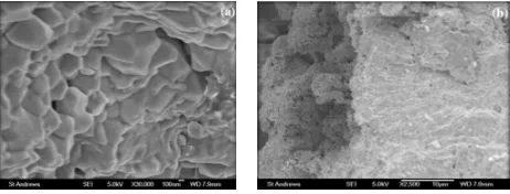
Fig. 14a shows the fracture surface of GDC electrolyte. It can be observed from the SEM photomicrograph that electrolyte is dense having a uniform microstructure which correlates with achievement of high OCV during fuel cell test. The anode-electrolyte bilayer is shown in Fig. 14b, which exhibits uniform
porous morphology of GDC-TiO0.2C0.8 anode layer onto the
surface of dense GDC electrolyte. Fig. 11 Plot of open circuit voltage (OCV) as a function of
operating temperature of the GDC+
TiO0.2C0.8/GDC/GDC+LSCF cell utilising moist hydrogen as
fuel and ambient air as oxidant
0.9 1.0 1.1 1.2 1.3 1.4
0.00 0.05 0.10 0.15 0.20 0.25 1 10k
700 oC
-Z // (o h m .c m 2 ) Z/ (ohm.cm2 )
(c)
2.0 2.5 3.0 3.5 4.0
0.0 0.5 1.0 1 20k 100
600 oC
-Z //(o h m .c m 2)
Z/(ohm.cm2)
(b)
5 10 15
0 5
20
200k
1
500 oC
-Z // (o h m .c m 2 )
Z/(ohm.cm2)
(a)
Journal
of
Materials
Chemistry
A
Accepted
Manuscript
[image:8.612.67.292.155.330.2] [image:8.612.334.529.156.466.2]ARTICLE
Journal Name
The present investigation indicates that titanium oxycarbide could be a potential anode material for IT-SOFC employing GDC based electrolyte. We believe that this is the first report on the application of titanium oxycarbide as anode material in a fuel cell and further research work is needed to be carried out in improving the performance of fuel cell employing titanium oxycarbide based anode material.
4 Conclusions
The present study indicates that titanium oxycarbide is an alternative anode material for SOFC. This is the first report on the possibility of application of a rare-earth free ceramic in the form of titanium oxycarbide as a potential fuel electrode material in IT-SOFC. Titanium oxycarbide has been found to be
stable under reducing conditions. Under oxidizing
environment, it starts to oxidize above 350 oC. The interaction
study of TiO0.2C0.8 with GDC under reducing conditions
confirms that there is no interaction at 900 oC under Ar+5%H2.
A peak power density of 130 mW/cm2 could be achieved
utilising TiO0.2C0.8 anode material in GDC electrolyte supported
SOFC at an operating temperature of 700 oC.
Acknowledgements
We thank the Engineering and Physical Sciences Research
Council (EPSRC)/ H2FC Supergen (EP/J016454/1,
EP/K015540/1) and the Royal Society (WRMA 2012/R2) for support.
References
1 J.-W. Kim, A. V. Virkar, K.-Z. Fung, K. Mehta and S. C.
Singhal,J. Electrochem. Soc., 1999, 146, 69-78.
2 S. deSouza, S. J. Visco and L. C. DeJonghe, Solid State
Ionics,1997, 98, 57-61.
3 Y. Jiang and A. V. Virkar, J. Electrochem. Soc., 2003,
150, A942-A951.
4 Y. J. Leng, S. H. Chan, K. A. Khor and S. P. Jiang, Int. J.
Hyd. Energy, 2004, 29,1025-1033.
5 S. Zha, Z. Cheng and M. Liu, J. Electrochem. Soc., 2007,
154, B201-B206.
6 A. Weber, B. Sauer, A. C. Muller, D. Herbstritt and E. I.
Tiffee, Solid State Ionics, 2002, 152–153, 543-550.
7 A. Buyukaksoy, V. Petrovsky and F. Dogan, ECS Trans.,
2012, 45, 509-514.
8 D. Simwonis, F. Tietz and D. Stöver, Solid State Ionics,
2000, 132, 241-251.
9 N. Q. Minh, J. Am. Ceram. Soc., 1993, 76, 563-588.
10 O. Porat, C. Heremans and H. L. Tuller, Solid State
Ionics, 1997, 94, 75-83.
11 G. Pudmich, B. A. Boukamp, M. Gonzalez-Cuenca, W.
Jungen, W. Zipprich and F. Tietz, Solid State Ionics,
2000, 135, 433-438.
12 J. T. S. Irvine, D. P. Fagg, J. Labrincha and F. M. B.
Marques, Catal. Today 1997, 38, 467-472.
13 S. Primdahl, J. R. Hansen, L. Grahl-Madsen and P. H.
Larsen, J. Electrochem. Soc.,2001, 148, A74-A81.
14 S. Tao, J. T. S. Irvine, Nature Mater.,2003, 2, 320-323.
15 A. Atkinson, S. Barnett, R. J. Gorte, J. T. S. Irvine, A. J.
McEvoy, M. Mogensen, S. C. Singhal and J. Vohs,
Nature Mater., 2004, 3, 17-27.
16 J. C. Ruiz-Morales, J. Canales-Vázquez, C. Savaniu, D.
Marrero-López, W. Zhou and J. T. S. Irvine, Nature,
2006, 439, 568-571.
17 D. N. Miller, A. K. Azad, H. Delpouve, L. Quazuguel, J. Zhou,
A. Sinha, F. Wormald and J. T.S. Irvine, J. Mater. Chem. A, 2016, 4, 5730-5736.
[image:9.612.67.290.59.222.2]18 A. T. Santhenam, in The Chemistry of Transition Metal
Fig. 13 Current–voltage (I-V) and current-power density (I-P)
plots of GDC+TiO0.2C0.8/GDC/GDC+LSCF cell at three
operating temperatures
Fig. 14The SEM photomicrographs exhibiting the (a) fracture surface of GDC Electrolyte and (b) electrolyte-anode bilayer.
Journal
of
Materials
Chemistry
A
Accepted
Manuscript
Published on 21 June 2016. Downloaded by University of St Andrews Library on 23/06/2016 09:48:12.
[image:9.612.66.297.293.381.2]Carbides and Nitrides (Ed: S. T. Oyama), Blackie Academic and Professional, London, 1996, 28.
19 A. Maitre and P. Lefort, Phys. Chem. Chem. Phys.,
1999, 1, 2311-2318.
20 T. Roisnel and J. Rodríguez-Carvajal, Mater. Sci. Forum,
2000, 378-381, 118-123.
21 P. Thompson, D. Cox and J. Hastings, J. Appl. Cryst.,
1987, 20, 79-83.
22 Y.G. Zainulin, S.I. Alyamovsky, and G.P. Shveikin, J.
Phy. Chem.Solids, 1978, 39, 29-31
23 B. C. H. Steele, Solid State Ionics, 2000, 129, 95-110.