Abstract
Three – Phase Sparged Reactors are widely used in Chemical, Bio-Chemical and Petrochemical Industrial processes. The advantages of these reactors include high mass and heat transfer rates,isothermal conditions and on-line catalyst addition and withdrawl. The high heat transfer rates of Three-Phase Sparged Reactors are particularly attractive for highly exothermic reactions where substantial reduction in heat transfer surface can lead to lower reactor cost . In the present paper mainly , the studies on heat transfer coefficients in slurry bubble columns and three- phase fluidized beds are examined . The author data is compared with the unified correlation of Suh and Deckwer [19] and important conclusions are drawn. The development of author’s unified correlation of heat transfer coefficients in Three- Phase Sparged Reactors are presented.
Keywords: energy dissipation rate, heat transfer
coefficient ,slurry bubble column , three- phase fluidized beds, unified correlation .
1. Introduction
Non-Agitated Three–Phase reactors with fluidized solids (“Three-Phase Sparged Reactors”) containing mainly slurry bubble column reactors and Three-Phase Fluidized beds are widely used in catalytic hydrogenations. Note worthy applications of TPSR are waste water treatment by supported bio-mass, fermenter and coal liquefaction processes. The main advantages of these reactors as compared to the fixed beds are uniform temperature and ease of catalyst exchange. Slurry operation may be either batch wise or continuous with respect to the flow of liquid and solid. In the latter case, the liquid (or slurry phase) may flow counter currently and co-currently to the gas. These reactors are sketched in Figure.1.
In the present paper the studies on heat transfer coefficients in slurry bubble columns and Three Phase Fluidised Beds are examined. The main characteristic feature of the Slurry Bubble Column is the suspension of solid particles by liquid motion induced alone by gas upward flow. The suspended particles are in most cases catalyst powders with diameters varies from several μm have a wide range of application. Slurry reactors are generally used for catalytic hydrogenation and oxidation reactions and for polymerization of olefins. In conversion of synthesis gas (Fischer – Tropsch synthesis, methanol production and methanation (SNG) the high liquid holdup is particularly advantageous for temperature control. TPFB reactors are widely used in the fields of petrochemical process for the catalytic hydrogenation of heavy petroleum feed stocks such as crude(H-oil) and Hydrogenation process, coal liquefaction (H–coal) process, and biotechnological applications in which the fluidized particles serve to support microorganisms in waste water treatment. Fluidization of large and heavy particles additionally requires co current liquid flow.
2. Literature Review – SBCs and
TPFBs
paraffin, kogasin and decalin or Al2O3 (ds≤
5 μm)/paraffin suspension were used as liquid or slurry phase. They observed that increasing solid contents also increase the htcs.
Michael and Reichert [2] measured the htcs in SBCs for olefin polymerization with Ziegler catalyst and some hydrocarbons (n–heptane, cyclohexane, Toluene, Exsol D80 and the suspensions of high density polyethylene (ds = 47 μm, 111 μm and 241 μm) in Exsol
D80) of the solid contents up to 34 wt % were used. They observed that small particles (ds = 47 μm to 111 μm), the htcs
decrease considerably for the solid concentration and increase slightly by increasing the solid concentration 241 μm diameter. They concluded the dependence of the slurry viscosity on the particle size. Saxena and coworkers [3] observed the ht in SBCs but they, however did not distinguish for the particle of the contributions of solids to the heat transfer. Hatate. [4] carried out work on Heat Transfer in Three - Phase upward flow of air – water – fine glass particles (28 μm ≤ ds ≤ 98 μm) at high fluid velocities where
slug flow is predominant. The htcs exhibited higher values than those of Two – Phase (g – l) upward flow in the range of solid concentration up to 40 wt % and increased slightly with increase of both gas and slurry velocities.
Chiu and Ziegler [5] measured the radial temperature profiles and wall – to – bed htcs in Three Phase Fluidised Beds of 5.08 cm diameter with glass beads and cylindrical porous alumina particles. The radial temperature distribution was observed to be parabolic, which indicates the existence of thermal resistance in the core region of the beds.
Muroyama. [6] measured the axial and radial temperature distributions region near the heat transfer surface and the wall–to–bed htcs in Three Phase Fluidised Beds of 9.56 cm diameter with glass, activated carbon and alumina beads on the basis of the axial dispersion model.
Muroyama. [7] applied the radial dispersion model in order to estimate the effective radial thermal conductivity, ker
and the apparent wall, heat transfer coefficient in the core region of the beds, hw from the measured radial temperature
profile. The influence of the liquid properties on the htcs in Three Phase Fluidised Beds was examined by Kato [8] Kang. [9], Saberian – Broudjenni [10], Kim . [11] Magiliotou [12] Zaidi. [13]and Rao Patnaik, K.S.K. [17]. Baker [14], Kato. [8] and Chiu and Ziegler [5] suggested an empirical dimensionless correlation between modified Nusselt and Reynolds numbers. The characteristic length and velocity scales used for defining the Nusselt and Reynolds numbers are the same as those proposed by Morooka [15] for the wall–to– bed
Mass Transfer Coefficients. . Recently
Nigam K.D.P and Schumpe. A [18] has reviewed the Three Phase Fluidised Beds and its fundamentals and analysis of practical systems.
For correlating the experimental data Suh. [16] proposed a model of Deckwer [1] for the heat transfer in bubble column
h = C [CPLρL KL (єv/ μL)1/2 ]1/2 (1)
With the modification of energy dissipation rate for the TPFBs
εν =
L
L L G G L L S S L
G
u
u
g
u
ε
ρ
ρ
ε
ρ
ε
ρ
ε
)
]
)(
[(
+
+
+
−
(2)
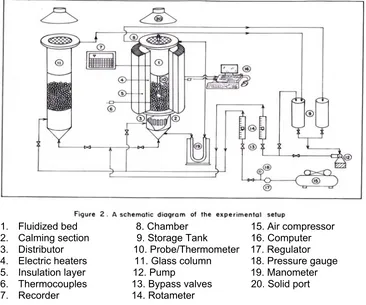
3. Experimental set-up
1. Fluidized bed 8. Chamber 15. Air compressor 2. Calming section 9. Storage Tank 16. Computer
[image:3.595.124.490.279.584.2]3. Distributor 10. Probe/Thermometer 17. Regulator 4. Electric heaters 11. Glass column 18. Pressure gauge 5. Insulation layer 12. Pump 19. Manometer 6. Thermocouples 13. Bypass valves 20. Solid port 7. Recorder 14. Rotameter
Table I: The following range of parameters are covered in the present author’s data
Particle sizes 0.17, 0.20, 0.25,0.36, 0.46, 0.50, 0.66mm
Bed material Fine river sand
Fluid mass Water, aq-glycerol
(5% to 40% wt %), Air Superficial liquid velocity 0.30 < uL <5 cm/sec
Superficial gas velocity 0 < uG < 3 cm/sec
Air pressure 0.65 kg/cm2 (gauge)
Diameter of the fluidized column 10.16 cm
Heating length of the fluidized column 100 cm
Viscosity of aqueous Glycerol 0.01 < μ < 0.0355 pa.s heated externally by means of a kanthal
resistance coil ( 6 kilowatt rate & 18 gauge) wound on the column and controlled through a voltage regulator. The 18 gauge kanthal wire having a total capacity of 6 k.w was wound with equal spacing over six slotted asbestos strips. A glass column having the same diameter and length as the test column was provided to observe the fluid bed conditions existing in the test column. The glass column has a similar distributor and a calming section as the test column.
4. Results and Discussion
The heat transfer in TPSR is influenced by the hydrodynamic effects of the gas, liquid and solid phase and the thermophysical properties of the liquid phase. The hydrodynamic variables can be represented by Reynolds number, NRe
and Froude number NFr and the thermo
physical properties by Prandtl number NPr.
The above discussion, therefore, is noted as follows
St = f(Re, Fr, Pr) (3)
if Stanton number NSt is used for the
calculating htcs. The mechanistic model based on Double Thermal Resistance method is compared with authors data and the correlation is almost independent of solid particles within the accuracy of ht experiments . The author applied the data with Surface Renewal Model and data having large scatter .It may be noted that Surface Renewal Model is purely a semi empirical requiring further development . However,at this stage it is difficult to substantiate the validity of these semi empirical models .
Insearching for alternative model, the author compared the experimental data with the calculated based on the Capillary Tube Model proposed by Suh and Deckwer[19].
Suh., [16] suggested a semi theoretical approach which is based on an extension of a correlation of htcs in Slurry Bubble Columns. Combining Higbie surface renewal model with Kolmogoroff’s concept of isotropic turbulence for evaluating the contact time of turbulent eddies at the heat exchange area.
The following semi theoretical relation derived by Deckwer, [1]
St = c (Re Fr Pr2)-1/4 (4)
Of the dimensionless, constant is set to c=0.1 for Two –Phase bubble columns and a pseudohomogenous phases are also agrees with this equation. From eq. (1) the htc is obtained as
h = c [KL ρL CPL
2 1
1 ⎟⎟⎠
⎞ ⎜⎜ ⎝ ⎛
μ
Pv ]12
(5) where PV is given by Ug g/ЄL to calculate
PV for TPFBs.
Pv = [(ul + ug)(εsρs + εlρl + εgρg) – Ulρl]g/εl
(6) Hence, the energy dissipation rate per unit volume in a TBFB is given by the energy input rate minus the energy recovery rate due to the increase of potential energy of the liquid phase.
With knowledge of the relative apparent bed viscosity of TPFBs and assuming the validity of c=0.1 for the htc takes the following form
h = 0.1 [Kl ρl CPl
2 1
⎟⎟ ⎠ ⎞ ⎜⎜ ⎝ ⎛
l b
v
P μ
η ]
2 1
(7)
As shown in figure.3,eq.(7) describes the experimental data of author without systematic diviation , and the correlation coefficient and the maximum deviation are 0.97 and 10% respectively. The author’s data in TPFBs is excellent agreement with semi theoretical equations proposed by Suh and Deckwer (19) .Therefore ,the capillary tube model appears fully appropriate to calculate viscosities of pseudoplastic fluids in TPFBs. This equation covers wall to bed and coil to bed, heat transfer over a wide range of operation modes as it applies to two – phase and SBCs and TPFBs operated at fully developed and incipient fluidization with Newtonian and non-Newtonian fluids.
Dividing eq (7) by ρl Cpl Ul gives the
Stl = 0.1 [ Pr2 Re1 Fr1
l b
μ
μ
*
1
v
P
]- 4
1
(8)
Which is of same form as eq (4) but additionally involves the relative apparent bed viscosity and the dimensionless group
*
v
P
=l l V
U
g
P
ρ
(9)which is the energy dissipation rate per unit volume of liquid divided by the energy recovery rate of the liquid due to its
increase in potential energy when flowing through the bed.
5. Conclusions
1. Wall-to-bed heat transfer coefficients in Three-Phase Sparged Reactors are calculated and compared with the Semi-Theoretical unified correlation of Suh and Deckwer [19] with ± 10% deviations.
2. The author’s data in Three-Phase Fluidized beds are excellent agreement with the Suh and Deckwer unified correlation to calculate the viscosities of pseudo plastic fluids.
3. This unified correlation covers wall-to-bed and coil-bed heat transfer over a wide range of operational modes.
4. This unified correlation applies to Two-Phase and SBCs and TPFBs operated at fully developed and incipient fluidization with Newtonian and non-Newtonian fluids.
5. Fan,L.S [20] rightly pointed out the limitations of semi theoretical models and directed the research towards bubble behavior in fluidized beds (bubble motion , bubble size and wake type ).
Notation
h = wall-to-bed heat transfer coefficient c = proportionality constant
cPL = heat capacity
KL = Thermal conductivity ЄV = Energy dissipation rate
uG = Superficial gas velocity
uL = Superficial liquid velocity
g = Acceleration due to gravity SBCs = Slurry buble columns
htc = Heat transfer coefficient TPFBs = Three phase fluidized beds
TPSRs = Three phase sparged reactors
Greek symbols
Є = phase holdup
μ = dynamic viscosity
ρ = density
Subscripts
References
[1]. Deckwer, W.D, Louisi, Y, Zaidi, A (1980) “Hydrodynamic properties of the Fischer-Tropsch slurry process”, Ind. Eng. Chem. Proc. Des. Dev., 19, 699-708 [2]. Michael, R and Reichert, K.H (1981) “Heat Transfer of
Polyethylene-Hydorcarbon Dispersions in Bubble Column Reactors”. Can.J. Chem. Eng., 59, 602-605
[3]. Saxena, S.C, Rao, N.S, and Saxena, A.C (1992 b) “Heat Transfer and gas holdup studies in a bubble Column, Air-Water-sand systems”, Can.J. Chem. Eng, 70, 33-41
[4].Hatate, Y, Tajiri, S, Fujita, T, Fukumoto, T, Ikari, A and Hano, T (1987) “Heat Transfer coefficient in Three-Phase vertical upflows of Gas-liquid-fine solid particles system”, J. Chem.Eng.Jap., 20, 568-574
[5]. Chiu, T.M and Ziegler, E.N(1983) “Heat Transfer in Three-Phase Fluidization beds”, AIChE. J, 29, 677
[6].Muroyama, K, Fukuma, M and Yashynishi, A (1984) “Wall-to-bed Heat Transfer coefficient in Gas-Liquid-Solid Fluidization Beds”, Can, J.Chem.Eng., 62, 199-208
[7].Muroyama, K, Fukuma, M and Yashynishi, A (1986) “Wall-to-bed Heat Transfer in liquid-solid and Liquid-Solid Fluidization beds” Part II : Gas-Liquid-Solid Fluidization Beds, Can,J.Chem.Eng., 64. 409-418
[8].Kato, Y., Uchida, K, Kago, T and Morooka, S(1981) “Liquid holdup and Heat Transfer Coefficient Between Bed and wall in liquid-solid and Gas-Liquid-Solid Fluidized Beds” Powder Technol, 28, 173-179
[9].Kang, Y.,Suh, I.S, and Kim, S.D(1985) “Heat Transfer characteristics of Three Phase Fluidized Beds”, Chem. Eng. Commun, 34, 1-13
[10]. Saberian-Broudjenni, M, Wild, G, Midoux.N, Charpentier, J.C (1985) “Contribution to the study of wall heat
transfer in reactors with a Gas-Liquid-Solid Fluidized Bed at low liquid velocities”, can. J. Chem. Eng, 63, 553.
[11].Kim, S.D, Kang, Y and Kwon, H.K (1986) “Heat Transfer characteristics of two and Three-Phase Slurry Fluidized Beds”, AIChE.J. 32, 1397.
[12].Magiliotou, M.,Chen, Y-M, and Fan, L.S (1988) “Bed immersed object heat transfer in a Three-Phase Fluidized Bed”, AIChE.J., 34, 1043-1047
[13].Zaidi, A, Benchekchou B, Karioun, M and Akharaz, A(1990 a) “Heat Transfer in Three-Phase Fluidized Beds with Non-Newtonian pseudoplastic solutions”, Chem. Eng. Commun, 93, 135-146
[14].Baker, C.G.J, Armstrong, E.R, Bergougnaou, M.A.(1978) “Heat Transfer in Three-Phase Fluidized Beds”,Powder Technol., 21, 195-204
[15]. Morooka, S., Kusakabe, K and Kato, Y (1980) “Mass Transfer Coefficient at the wall of a rectangular Fluidized bed for Liquid-Solid and Gas-Liquid-Solid systems”, Int.Chem.Eng., 20, 433-438
[16]. Suh, I.S.,Jin, G.T and Kim, S.D(1985) “Heat Transfer coefficient in Three-Phase Fluidized Beds”, Int. J. multiphase flow, 11, 255-259
[17] .Rao Patnaik, K.S.K.,
Subrahaminayam, S, Sadasiva Rao, P(1998) “Wall-to-bed heat transfer in Three-Phase Fluidized beds : Part I “ Journal of energy, heat and mass transfer, 20, 101-107
[18].Nigam K.D.P and Schumpe. A (1996) “Three-Phase sparged reactors” 8, Gordon and Breach publishers SA
[19].Suh I.S and Deckwer, W.D (1989) “Unified correlation of heat transfer coefficients in three-phase fluidized beds”, Chem. Eng. Sci., 44, 6,1455-1458.