IJIRT 143896
INTERNATIONAL JOURNAL OF INNOVATIVE RESEARCH IN TECHNOLOGY108
USING FUZZY LOGIC IN INDUCTION MOTOR FOR
DIRECT TORQUE CONTROL TO REDUCE LOSSES
Kamini Aloria, Ameenuddin Ahmad
1
Al-Falaha University, Dhuaj.
2
Assistant Professor, Al-Falaha University, Dhuaj.
Abstract- This paper presents an improved direct torque control in induction motor that based on fuzzy logic technique. we compaire both system (1)conventional method of direct torque control (2) DTC using fuzzy logic{FLDTC} benefits and its drawbacks. Major problem arise in conventional method DTC is torque ripple factor so we discuss how to overcome this problem .also we discuss modification in it with the help of fuzzy logic
Index Terms- Induction motor ,torque control , fuzzy logic ,reducing torque ripple factor
I. INTRODUCTION
IN 3 phase ac induction motor work on electromagnetic induction where they have flux is going to help develop where as torque generation during rotation process in rotor this paper we discuss how we speed control in ac induction motor
In AC induction motor we have 2 method of speed control as
[a]conventional method which we done as 1)Space vector modulation(SVM) 2)using switching means used more no of switches which increase the complexity in the system 3)Multi level inverter [II] using Fuzzy logic control speed of induction motor in this process it work on [o] and [1] but it cause complexity if variable result is come (for example change in temperature from hot to cold but moderate condition cause complexity) so know we discuss how we done improvement in it
By using FUZZY logic we used artificial intelligence method with it so that machine is going to learn continously new output changes or modification done in it time to time.
II. BASIC DTC PRINCIPLE
Direct torque control (DTC)
is receiving wide attention in the recent literature. DTC minimizes the use of machine parameters. This type of control is essentially a sliding mode stator flux-oriented control. The
DTC uses the hysteresis band to directly control the flux
and torque of the machine. When the stator flux falls out
side the hysteresis band, the inverter switching stator is
changed so that the flux takes an optimal path toward the desired value. The name direct torque control is derived from the
fact that on the basis of the errors between the reference
and the estimated values of torque and flux it is possible
to directly control the inverter states in order to reduce
the torque and flux errors within the prefixed band limits
.
The main advantages of DTC are
(1) robust and fast torque response(2)no requirements for coordinate transformation(3)no requirements for PWM pulse generation(4)current regulators .
The major disadvantage of the
1)DTC drive is the steady state ripples in torque and flux.
2)The pulsations in flux and torque affect the accuracy of
speed estimation.3)It also results in higher noise and in harmonic losses.
IJIRT 143896
INTERNATIONAL JOURNAL OF INNOVATIVE RESEARCH IN TECHNOLOGY109
amplitude control of flux and torque hysteresis bands , open loop control of hysteresis band amplitude , and fuzzy logic based variable amplitude control of flux and torque hysteresis bands . But these are complex in nature for easy implementation. The ripple in the torque and flux can be easily reduced by applying the selected inverter vector only for the part and not for the entire switching period unlike that in the classical DTC. This technique, also known as duty ratio control, increases the number of voltage vectors beyond the available eight discrete ones, without any
increase in the number of semiconductor switches in the inverter The work in refers to fuzzy logic duty ratio control but fails to give any details. Similar work presented in claims reduction in ripple to one-third value. However, simulation results were shown for low speed operation only using a fuzzy controller with three membership functions for inputs and output. They have shown an algorithm for optimized value of reference flux based on reference load torque.
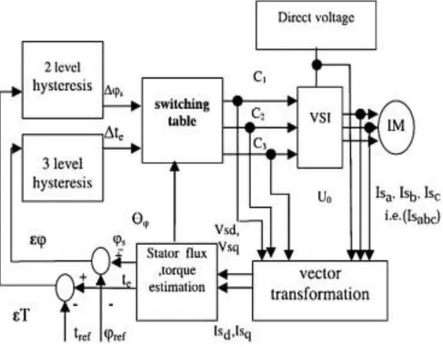
Fig 1.The basic block diagram of the DTC
The work presented in this paper considers the design of new fuzzy logic controller with five membership functions for the inputs and output along with the optimized flux algorithm based on maximum reference value of the electromagnetic torque to adjust the “duty ratio” of inverter switching vectors. The present work shows much better performance
(reduced ripple) though it has some similarities with those in . A significant reduction in the ripple than that in has been achieved in the present work. The adaptive PI controller that is based on look-up Table is used for outer speed loop for precision speed tracking.
IJIRT 143896
INTERNATIONAL JOURNAL OF INNOVATIVE RESEARCH IN TECHNOLOGY110
III. CONTROLLER USED IN DTC
INTRODUCTION
In DTC estimated flux magnitude and torque are compared with their refernce values if either then estimated torque* and flux** compaired with
refernce value if deviation is more then allow tolernce transistor of variable frequency drive *[TORQUE-It is the rotational force that help in during rotation process ]
**[FLUX –IT IS DEFINE AS no of lines of force passing throw per unit area]
Fig HIGH LEVEL BLOCK diadgram of DTC
If we used better controller benefits is arise that (1) good feedback we have to recive (2)reduced mechanical losses (3) response time is going to reduced
The difference between the traditional vector control and the DTC is that the dtc has no fixed switching pattern whereas DTC switches the inverter according to the load needs.these values of fed to three level
comparators of the torque and two level comparator of flux so its output is compaired with refernce signal IN DTC we donot have fixed switching pattern. In it signals are fed to the voltage vector selector which have values fall in [0] and [1]
Voltage space vectors They have 8 output position
IJIRT 143896
INTERNATIONAL JOURNAL OF INNOVATIVE RESEARCH IN TECHNOLOGY111
VOLTAGE SPACE VECTOR
IV. TORQUE RIPPLE
With a larger samplingtime ,the possibilities of torque overshoot and undershoot is higher .by reducing the sampling period .a better torque trajectory is obtained .switching frequency is increased by changing the duty ratio of the selected voltage vector during each switching period according to the magnitude of the torque error and position of the stator flux.here a zero voltage vector is choosen to reduce the torque.
plot(Range(1:5,1:2), 'DisplayName', 'Range(1:5,1:2)', 'YDataSource', 'Range(1:5,1:2)'); figure(gcf)
Matlab Code For Fuzzy Interference System (FIS) Generation of Fuzzy Interference System (named motor5) in the bmatlab is implemented using the below given code:
[SYSTEM]
>> Name='motor5'; Type='mamdani'; version=2.0; NumInputs=3; NumOutputs=3; NumRules=35; AndMetod='min'; OrMethod='max'; ImpMethod='max';
AggMethod='max'; DeFuzzMethod='mom'; [INPUT1]
>> Name='Hphi'; Range=[-0.1 0.1]; NumMFs=2;
Mf1='N':'trapmf';[-0.142 -0.122 -0.0108 0.000265]; Mf2='P':'trapmf';[-0.000794 0.00555 0.116 0.136]; [INPUT2]
>> Name='Hte'; Range=[-1 1]; NumMFs=3;
Mf1='NT':'trapmf';[-1.4 -1.2 -0.1 0]; Mf2='PT':'trapmf';[0 0.1 1.2 1.4]; Mf2='ZT':'trapmf';[-0.0291 0 0.0291]; [INPUT3]
>> Name='Sector'; Range=[0 360]; NumMFs=7;
Mf1='T4':'trapmf';[-23.1 -22.4 27.1 40.48]; Mf2='T5':'trimf';[20.4 61.4285714285714 99.5]; Mf3='T6':'trimf';[80.5 121 160];
Mf4='T1':'trimf';[141 180 220.476190476191]; Mf5='T2':'trimf';[200 238.571428571429 280]; Mf6='T41':'trimf';[320 333.809523809524 395 404 ]; Mf7='T3':'trimf';[259 292.857142857143 340]; [OUTPUT]
IJIRT 143896
INTERNATIONAL JOURNAL OF INNOVATIVE RESEARCH IN TECHNOLOGY112
Mf1='v0':'trimf';[0.6303392063492064 0.215207936507936 0.753807936507936]; Mf2='v1':'trimf';[5.3 5.84 6.48677248677249]; Mf2='v2':'trimf';[.8976545678 .0145678546 .9870000768];
Mf2='v3':'trimf';[3.4 4.67 8.78646563828828]; Mf2='v4':'trimf';[.9876524433 .00983678182 .762436718739];
Mf2='v5':'trimf';[7.89 9.86767 13.9738836721]; Mf2='v6':'trimf';[.092773576215 .2771536781819 .75];
Mf2='v7':'trimf';[6.7624768192 8.927389901 9.082797823738];
INPUT GRAPH IN MATLAB WINDOW Name='Sector';
Range=[0 360]; NumMFs=7;
-50 0 50 100 150 200 250 300 350
-50 0 50 100 150 200 250 300 350
B C D
A
B
0 50 100 150 200 250 300 350 400 450
C
OUTPUT IN MATLAB WINDOW Name='output1';
NumMFs=8;
plot(ans(1,1:3), 'DisplayName', 'ans(1,1:3)', 'YDataSource', 'ans(1,1:3)'); figure(gcf) plot(ans(1:4,1:3), 'DisplayName', 'ans(1:4,1:3)', 'YDataSource', 'ans(1:4,1:3)'); figure(gcf)
1 2 3 4
IJIRT 143896
INTERNATIONAL JOURNAL OF INNOVATIVE RESEARCH IN TECHNOLOGY113
-1 0 1 2 3 4 5 6 7 8 9
7.5 8.0 8.5 9.0 9.5 10.0 10.5
C B C
A
C
0 7 14
B
M CODE IN MATLAB WINDOW
V. CONCLUSION
The proposed system approach leads to imprpvement in the response of an induction motor (IM) through direct torque control (DTC) based on fuzzy logic technique switching table.The fuzzy control strategy on a simulation platform using MATLAB/SIMULINK has been built which includes induction motor d-q model,inverter model ,fuzzy
logic switching table and the stator flux and torque estimator.The simulation results verified the new control strategy.
The FLDTC technique leads to remarkable reduction in the ripple of torque as wll as current compared to the conventional DTC THE improvements in the system may be summarizes as below:
IJIRT 143896
INTERNATIONAL JOURNAL OF INNOVATIVE RESEARCH IN TECHNOLOGY114
iii)The speed response has been fast as is evident from reduction in the response time
iv)The catch up time required at any time is less than the time required in the conventional method
The above conclusion may be confirmed from the output .Hence the DTC with fuzzy controller for induction motor speed control shows a marked improvement over the convention DTC
VI. FUTURE SCOPE OF RESEARCH
Due to limitation of time and constraint of resources,the current project work is restricted to specific functionality only.
But in case ,such obstruction can be overcome the current project work may be extended to design of an improved direct torque control by using double – fuzzy logic technique .
VII. RESULT
In above process we have to observe that if we consider various values for change output so we have easily plot various graph so on behave of it we easyily understand the performance flauctuation .in this paper we have to discuss the two type of torque control process 1)DTC(direct torque control method) 2) DTCFL(direct torque control using fuzzy logic in it we compare both the process each other and as we performe the operation on matlab so we observe various forms of output
REFERENCES
[1]. I. Takahashi, “A new quick response and high efficiency control strategy of induction motor,” IEEE Industry Application Transactions, Vol. IA-22, pp. 820-827, Sept/Oct.1986.
[2]. Y. A. Chapuis, D. Roye, and J. Davoine, “Principles and Implementation of direct torque control by stator flux orientation of an induction motor,” in Proc. PESC, 1995, pp.
[3]. P. Titinen, M. Surandra, ”The next generation motor control method, DTC direct torque control,” Power Electronics, Drives and Energy System for Industrial Growth, 1996, Pro. of the 1996 International Conf. Vol. 1, pp. 37-43, 1996.
[4]. James N. Nash, “Direct Torque Control, Induction Motor Vector
[5] G. Yang and T.-H. Chin, “Adaptive-speed identification scheme for a vector-controlled speed sensorless inverter-induction motor drive,” IEEE
Trans. Ind. Applicat., vol. 29, pp. 820–825, July/Aug.
1993.
[6] H. Kubota, K. Matsuse, and T. Nakano, “Dsp-based speed adaptive flux observer of induction motor,” IEEE Trans. Ind. Applicat., vol. 29, pp. 344– 348, Mar./Apr. 1993.
[7] H. Kubota and K. Matsuse, “Speed sensorless field-oriented control of induction motor with rotor resistance adaptation,” IEEE Trans. Ind. Applicat., vol. 30, pp. 1219–1224, Sept./Oct. 1994.
[8] C.-M. Lee and C.-L. Chen, “Observer-based speed estimation method for sensorless vector control of induction motors,” Proc. IEE—Contr. Theory
Applicat., vol. 145, pp. 359–363, May 1998.
[9] Y.-R. Kim, S.-K. Sul, and M.-H. Park, “Speed sensorless vector control of an induction motor using an extended Kalman filter,” in Conf. Rec.IEEE-IAS
Annu. Meeting, 1992, pp. 594–599.
[10] B.-J. Brunsbach, G. Henneberger, and T. Klepsch, “Realization of a sensorless field-oriented controlled drive with an induction motor with a Kalman filter,” in Proc. PCIM Conf., 1991, pp. 53– 64.
[11] J. Al-Tayie and P. Acarnley, “Estimation of speed, stator temperature and rotor temperature in cage induction motor drive using the extended Kalman filter algorithm,” Proc. IEE—Elect. Power
Applicat., vol. 144, pp. 301–309, Sept. 1997.
[12] P. Vas, Sensorless Vector and Direct Torque
Control. Oxford, U.K.: Oxford Univ. Press, 1998.
[13] H. Tajima and Y. Hori, “Speed sensorless field orientation control of the induction machine,” in
Conf. Rec. IEEE-IAS Annu. Meeting, vol. 1, 1991, pp.