TR-069
CPE WAN Management Protocol
Issue: 1 Amendment 5 Issue Date: November 2013Notice
The Broadband Forum is a non-profit corporation organized to create guidelines for broadband network system development and deployment. This Broadband Forum Technical Report has been approved by members of the Forum. This Broadband Forum Technical Report is not binding on the Broadband Forum, any of its members, or any developer or service provider. This Broadband Forum Technical Report is subject to change, but only with approval of members of the Forum. This Technical Report is copyrighted by the Broadband Forum, and all rights are reserved. Portions of this Technical Report may be copyrighted by Broadband Forum members.
This Broadband Forum Technical Report is provided AS IS, WITH ALL FAULTS. ANY PERSON HOLDING A COPYRIGHT IN THIS BROADBAND FORUM TECHNICAL REPORT, OR ANY PORTION THEREOF, DISCLAIMS TO THE FULLEST EXTENT PERMITTED BY LAW ANY REPRESENTATION OR WARRANTY, EXPRESS OR IMPLIED, INCLUDING, BUT NOT LIMITED TO, ANY WARRANTY:
(A) OF ACCURACY, COMPLETENESS, MERCHANTABILITY, FITNESS FOR A PARTICULAR PURPOSE, NON-INFRINGEMENT, OR TITLE;
(B) THAT THE CONTENTS OF THIS BROADBAND FORUM TECHNICAL REPORT ARE SUITABLE FOR ANY PURPOSE, EVEN IF THAT PURPOSE IS KNOWN TO THE COPYRIGHT HOLDER;
(C) THAT THE IMPLEMENTATION OF THE CONTENTS OF THE TECHNICAL REPORT WILL NOT INFRINGE ANY THIRD PARTY PATENTS,
COPYRIGHTS, TRADEMARKS OR OTHER RIGHTS.
By using this Broadband Forum Technical Report, users acknowledge that
implementation may require licenses to patents. The Broadband Forum encourages but does not require its members to identify such patents. For a list of declarations made by Broadband Forum member companies, please see http://www.broadband-forum.org. No assurance is given that licenses to patents necessary to implement this Technical Report will be available for license at all or on reasonable and non-discriminatory terms. ANY PERSON HOLDING A COPYRIGHT IN THIS BROADBAND FORUM TECHNICAL REPORT, OR ANY PORTION THEREOF, DISCLAIMS TO THE FULLEST EXTENT PERMITTED BY LAW (A) ANY LIABILITY (INCLUDING DIRECT, INDIRECT, SPECIAL, OR CONSEQUENTIAL DAMAGES UNDER ANY LEGAL THEORY) ARISING FROM OR RELATED TO THE USE OF OR
RELIANCE UPON THIS TECHNICAL REPORT; AND (B) ANY OBLIGATION TO UPDATE OR CORRECT THIS TECHNICAL REPORT.
Broadband Forum Technical Report may be copied, downloaded, stored on a server or otherwise re-distributed in their entirety only, and may not be modified without the advance written permission of the Broadband Forum.
The text of this notice must be included in all copies of this Broadband Forum Technical Report.
Issue History Issue Number Approval Date Publication Date
Issue Editor Changes
Issue 1 May 2004 Jeff Bernstein, 2Wire
Tim Spets, Westell
Issue 1 Issue 1
Amendment 1 November 2006 Jeff Bernstein, 2Wire John Blackford, 2Wire
Mike Digdon, SupportSoft Heather Kirksey, Motive William Lupton, 2Wire Anton Okmianski, Cisco
Clarification of original document
Issue 1
Amendment 2 November 2007 William Lupton, 2Wire Davide Moreo, Telecom
Italia CWMP Version 1.1: Multicast Download support, 10 AUTONOMOUS TRANSFER COMPLETE event, AutonomousTransferComplete method, additional Download fault codes, interoperability clarifications, minor editorial changes.
Issue 1
Amendment 3 November 2010 John Blackford, Pace Heather Kirksey,
Alcatel-Lucent
William Lupton, Pace
CWMP Version 1.2: Small updates for IPv6 related to DHCP, Additions for Software Module Management support (including new RPCs, Inform Event Codes, fault codes, and an Annex on UUIDs),
ScheduleDownload RPC, and CancelTransfer RPC. Issue 1
Amendment 4 July 2011 Sarah Banks, Cisco Andrea Colmegna,
FASTWEB Tim Spets, Motorola Mobility
CWMP Version 1.3: Added Proxy management support and added Annex J and Appendix I. Table 4 Session timeout updated. Removed xsd Section A.6.
Added Alias-Based Addressing additions, Section 3.6.1, Appendix II, and RPC Definition updates. Issue 1
Amendment 5 11 November
2013
8 January
2014 John Blackford, Pace Mike Digdon, Aptean CWMP Version 1.4: Added XMPP Connection Request support (Annex
K and Appendix III), CPE standby-related behaviors (Annex L), UDP Lightweight Notification support (Annex M), and several other small clarifications/enhancements.
Comments or questions about this Broadband Forum Technical Report should be directed to [email protected].
Editors John Blackford Mike Digdon
Pace Aptean
BroadbandHome™ Working Group Chairs
John Blackford Jason Walls
Pace QACafe
Table of Contents
1 Introduction ... 16
1.1 Functional Components ... 16
1.1.1 Auto-Configuration and Dynamic Service Provisioning ... 16
1.1.2 Software/Firmware Image Management ... 17
1.1.3 Software Module Management ... 17
1.1.4 Status and Performance Monitoring ... 17
1.1.5 Diagnostics ... 17
1.2 Positioning in the End-to-End Architecture ... 17
1.3 Security Goals ... 18 1.4 Architectural Goals ... 18 1.5 Assumptions ... 19 1.6 Terminology ... 20 1.7 Abbreviations ... 22 1.8 Document Conventions ... 24 2 Architecture ... 26 2.1 Protocol Components ... 26 2.2 Security Mechanisms ... 27 2.3 Architectural Components ... 27 2.3.1 Parameters ... 27 2.3.2 File Transfers ... 28
2.3.3 CPE Initiated Sessions ... 28
2.3.4 Asynchronous ACS Initiated Sessions ... 29
3 Procedures and Requirements ... 30
3.1 ACS Discovery ... 30
3.2 Connection Establishment ... 33
3.2.1 CPE Connection Initiation ... 33
3.2.2 ACS Connection Initiation ... 36
3.3 Use of TLS and TCP ... 38
3.4 Use of HTTP ... 40
3.4.1 Encoding SOAP over HTTP ... 40
3.4.2 Sessions ... 41 3.4.3 File Transfers ... 43 3.4.4 Authentication ... 43 3.4.5 Digest Authentication ... 44 3.4.6 Additional HTTP Requirements ... 45 3.4.7 HTTP Compression ... 45 3.5 Use of SOAP ... 46 3.6 RPC Support Requirements ... 52
3.6.1 Alias-Based Addressing Mechanism Requirements ... 53
3.7 Session Procedures ... 56
3.7.1 CPE Operation ... 56
3.7.2 ACS Operation ... 66
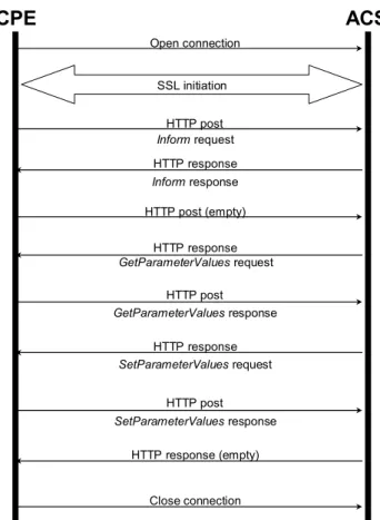
3.7.3 Transaction Examples ... 69
Normative References ... 71
Annex A. RPC Methods ... 74
A.1Introduction ... 74
A.2RPC Method Usage ... 74
A.2.1 Data Types ... 74
A.2.2 Instance Identifiers ... 75
A.2.2.1 Instance Number Identifier ... 75
A.2.2.2 Instance Alias Identifier ... 76
A.2.3 Other Requirements ... 76
A.3Baseline RPC Messages ... 77
A.3.1 Generic Methods ... 77
A.3.1.1 GetRPCMethods ... 77
A.3.2 CPE Methods ... 78
A.3.2.1 SetParameterValues ... 78 A.3.2.2 GetParameterValues... 81 A.3.2.3 GetParameterNames... 82 A.3.2.4 SetParameterAttributes ... 84 A.3.2.5 GetParameterAttributes ... 88 A.3.2.6 AddObject ... 90 A.3.2.7 DeleteObject ... 93 A.3.2.8 Download ... 95 A.3.2.9 Reboot ... 100
A.3.3 ACS Methods ... 101
A.3.3.1 Inform ... 101
A.3.3.2 TransferComplete ... 104
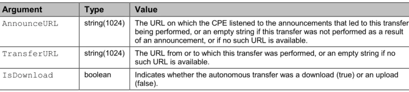
A.3.3.3 AutonomousTransferComplete ... 105
A.4Optional RPC Messages ... 107
A.4.1 CPE Methods ... 107
A.4.1.1 GetQueuedTransfers ... 107 A.4.1.2 ScheduleInform ... 107 A.4.1.3 SetVouchers ... 108 A.4.1.4 GetOptions ... 108 A.4.1.5 Upload ... 110 A.4.1.6 FactoryReset ... 112 A.4.1.7 GetAllQueuedTransfers ... 112 A.4.1.8 ScheduleDownload ... 114 A.4.1.9 CancelTransfer ... 118 A.4.1.10ChangeDUState ... 118
A.4.2 ACS Methods ... 122
A.4.2.1 Kicked ... 122
A.4.2.2 RequestDownload ... 122
A.4.2.3 DUStateChangeComplete ... 123
A.4.2.4 AutonomousDUStateChangeComplete ... 126
A.5Fault Handling ... 129
A.5.1 CPE Fault Codes ... 129
A.6RPC Method XML Schema ... 131
Annex B. Removed ... 132
Annex C. Signed Vouchers ... 133
C.1Overview ... 133
C.2Control of Options Using Vouchers ... 133
C.3Voucher Definition ... 134
Annex D. Web Identity Management ... 138
D.1Overview ... 138
D.2Use of the Kicked RPC Method ... 138
D.3Web Identity Management Procedures ... 139
D.4LAN Side Interface ... 140
Annex E. Signed Package Format ... 142
E.1 Introduction ... 142
E.2 Signed Package Format Structure ... 142
E.2.1 Encoding Conventions ... 143
E.3 Header Format ... 143
E.4 Command List Format ... 143
E.4.1 Command Types ... 144
E.4.2 End Command ... 145
E.4.3 Extract and Add Commands ... 145
E.4.4 Remove Commands ... 146
E.4.5 Move Commands ... 146
E.4.6 Version and Description Commands ... 147
E.4.7 Timeout Commands ... 147
E.4.8 Reboot Command ... 149
E.4.9 Format File System ... 149
E.4.10 Minimum and Maximum Version Commands ... 149
E.4.11 Role Command ... 151
E.4.12 Minimum Storage Commands ... 151
E.4.13 Required Attributes Command ... 151
E.5 Signatures ... 152
Annex F. Device-Gateway Association ... 154
F.1 Introduction ... 154 F.1.1 Terminology ... 154 F.2 Procedures ... 155 F.2.1 Gateway Requirements ... 155 F.2.2 Device Requirements ... 156 F.2.3 ACS Requirements ... 157
F.2.4 Device-Gateway Association Flows ... 158
F.2.5 DHCP Vendor Options ... 159
F.3 Security Considerations ... 160
Annex G. Connection Request via NAT Gateway ... 162
G.2Procedures ... 162
G.2.1 CPE Requirements ... 163
G.2.1.1 Binding Discovery ... 164
G.2.1.2 Maintaining the Binding ... 165
G.2.1.3 Communication of the Binding Information to the ACS ... 166
G.2.1.4 UDP Connection Requests ... 168
G.2.2 ACS Requirements ... 169
G.2.2.1 STUN Server Requirements ... 169
G.2.2.2 Determination of the Binding Information ... 170
G.2.2.3 UDP Connection Requests ... 171
G.2.3 Message Flows ... 173
G.3Security Considerations ... 176
Annex H. Software Module Management UUID Usage ... 177
H.1Overview ... 177
H.2UUID Generation Requirements ... 178
H.3CPE Requirements ... 178
Annex I. ... 179
Annex J. CWMP Proxy Management ... 180
J.1 Introduction ... 180
J.2 The Virtual CWMP Device Mechanism ... 181
J.2.1 Data Model Requirements ... 181
J.2.2 Proxied Device Identification and Modeling ... 181
J.2.3 Proxied Device Availability ... 182
J.3 The Embedded Object Mechanism ... 183
J.3.1 Proxied Device Data Modeling and Provisioning ... 183
J.3.2 Proxied Device Availability ... 183
Annex K. XMPP Connection Request ... 185
K.1Introduction ... 185 K.2Procedures ... 185 K.2.1 CPE Requirements ... 187 K.2.1.1 XMPP Connection Encryption ... 189 K.2.1.2 XMPP Channel Authentication ... 189 K.2.1.3 XMPP Connection Request ... 189 K.2.2 ACS Requirements ... 191 K.2.2.1 XMPP Connection Encryption ... 191 K.2.2.2 XMPP Connection Request ... 191 K.2.3 Message Flows ... 192 K.2.3.1 Connection Request ... 192
K.2.3.2 Connection Request Successful Response ... 193
K.2.3.3 Connection Request Error Response ... 193
K.3XMPP Server Deployment Requirements ... 194
K.4Security Considerations ... 194
Annex L. CPE standby-related behaviors ... 195
L.2 Procedures ... 196
L.2.1 Use of WAKEUP Event ... 196
L.2.2 Conditions requiring a WAKEUP Event ... 196
L.2.3 When to deliver a WAKEUP Event ... 196
L.2.4 Management of standby modes by the ACS ... 196
Annex M. UDP Lightweight Notification ... 198
M.1Introduction ... 198 M.2Procedures ... 198 M.2.1 CPE requirements ... 198 M.2.2 ACS requirements ... 199 M.2.3 UDPLightweightNotification message ... 199 M.2.4 Message arguments ... 200 M.2.5 UDPLightweightNotification XML Schema ... 201 M.2.6 UDPLightweightNotification example ... 201
Appendix I. CPE Proxier Implementation Guidelines ... 202
I.1 Introduction ... 202
I.2 Common Guidelines for the Virtual CWMP Device and Embedded Object Mechanisms ... 202
I.2.1 Unsupported CWMP RPC Commands by the Proxy Protocol ... 202
I.2.2 Support for Proxy Protocol Methods with no Matching RPC ... 202
I.2.3 Support for Transactional Integrity ... 203
I.3 Embedded Object Mechanism ... 203
I.3.1 Device Discovery ... 203
I.3.2 CPE Proxier use of Polling ... 204
I.3.3 ACS Query of RPC Execution ... 204
I.3.4 Support for Proxy Protocol Methods Reboot and Download ... 204
I.4 Virtual CWMP Device Mechanism ... 205
I.4.1 Device Discovery ... 205
I.4.2 Request for Session Timeout Extension ... 205
I.4.3 CPE Proxier use of Caching ... 206
I.4.4 Virtual CWMP Device Error Scenarios ... 207
I.5 Proxy Management Support Example... 208
Appendix II. Alias-Based Addressing Mechanism – Theory of Operations ... 210
II.1Introduction ... 210
II.2Multi-Instance Objects Definition ... 210
II.3Instance Alias as a Data Model Parameter ... 211
II.4Multi-Instance Object Creation ... 211
II.5AddObject RPC Extension ... 212
II.6Auto-Creation of Object Instances ... 212
II.7Support for Alias-Based Addressing Mechanism ... 213
Appendix III. XMPP Connection – Theory of Operations ... 214
III.1 Introduction ... 214
III.3 XMPP Identities ... 214
III.3.1 CPE Considerations ... 214
III.4 Establishing an XMPP Connection ... 215
III.4.1 Determining the XMPP Server Address and Port ... 215
III.4.2 XML Streams ... 216
III.4.3 XMPP Connection Encryption ... 216
III.4.4 XMPP Channel Authentication ... 216
III.4.5 Reconnecting to the XMPP Server ... 216
III.5 Maintaining an XMPP Connection ... 217
III.6 Deployment Considerations ... 217
Appendix IV. UPnP IGD and HTTP Connection Requests ... 219
IV.1 Introduction ... 219
IV.2 NAT Port Mapping Theory of Operation ... 219
IV.2.1 Discovery and External IP Address Retrieval... 219
IV.2.2 Procedures for WANPPPConnection:1 ... 220
IV.2.3 Procedures for WANIPConnection:2... 223
IV.2.4 Handling Changes ... 224
IV.3 IPv6 Pinhole Theory of Operation ... 224
IV.3.1 Discovery ... 225
IV.3.2 Procedures ... 225
List of Tables
Table 1 – Protocol layer summary ... 26
Table 2 – Encapsulated Vendor Specific Options ... 31
Table 3 – Session Retry Wait Intervals ... 35
Table 4 – SOAP Header Elements ... 50
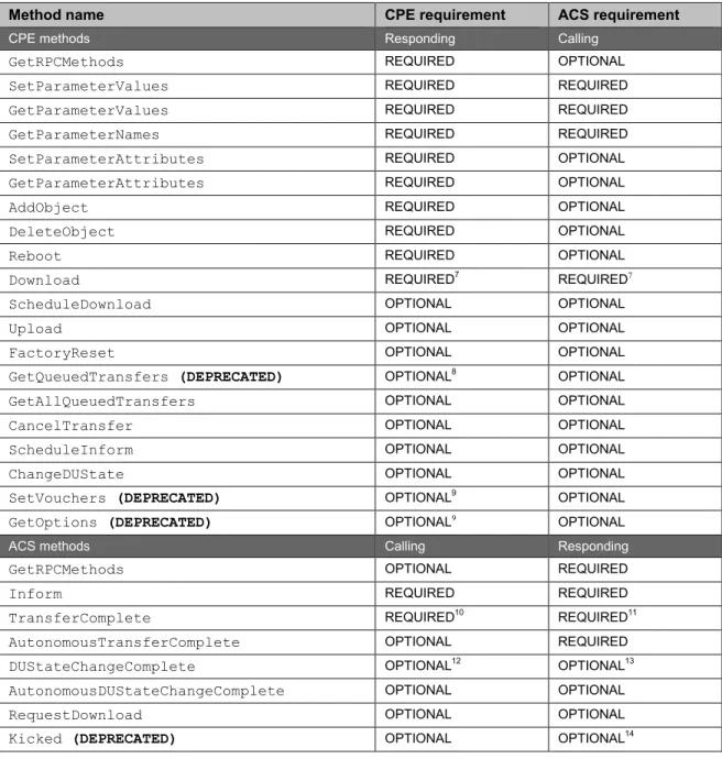
Table 5 – RPC message requirements ... 52
Table 6 – Inferring ACS CWMP Version 1.0-1.3 from CWMP Namespace ... 57
Table 7 – CPE Message Transmission Constraints ... 58
Table 8 – Event Types ... 61
Table 9 – Inferring CPE CWMP Version 1.0-1.3 from CWMP Namespace ... 66
Table 10 – ACS Message Transmission Constraints ... 67
Table 11 – CWMP Version Negotiation ... 70
Table 12 – Data types ... 74
Table 13 – GetRPCMethods arguments ... 77
Table 14 – GetRPCMethodsResponse arguments ... 78
Table 15 – SetParameterValues arguments ... 78
Table 16 – SetParameterValuesResponse arguments ... 79
Table 17 – ParameterValueStruct definition ... 80
Table 18 – GetParameterValues arguments ... 82
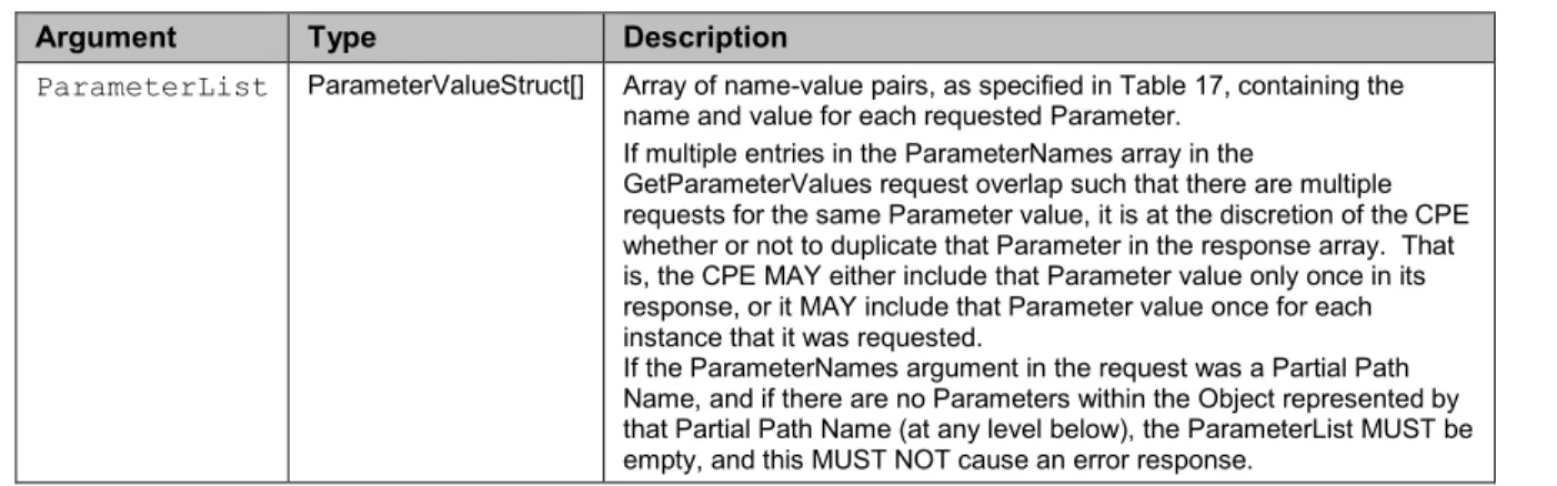
Table 19 – GetParameterValuesResponse arguments ... 82
Table 20 – GetParameterNames arguments ... 82
Table 21 – GetParameterNamesResponse arguments ... 83
Table 22 – ParameterInfoStruct definition ... 83
Table 23 – SetParameterAttributes arguments ... 85
Table 24 – SetParameterAttributesResponse arguments ... 85
Table 25 – SetParameterAttributesStruct definition ... 85
Table 26 – GetParameterAttributes arguments ... 88
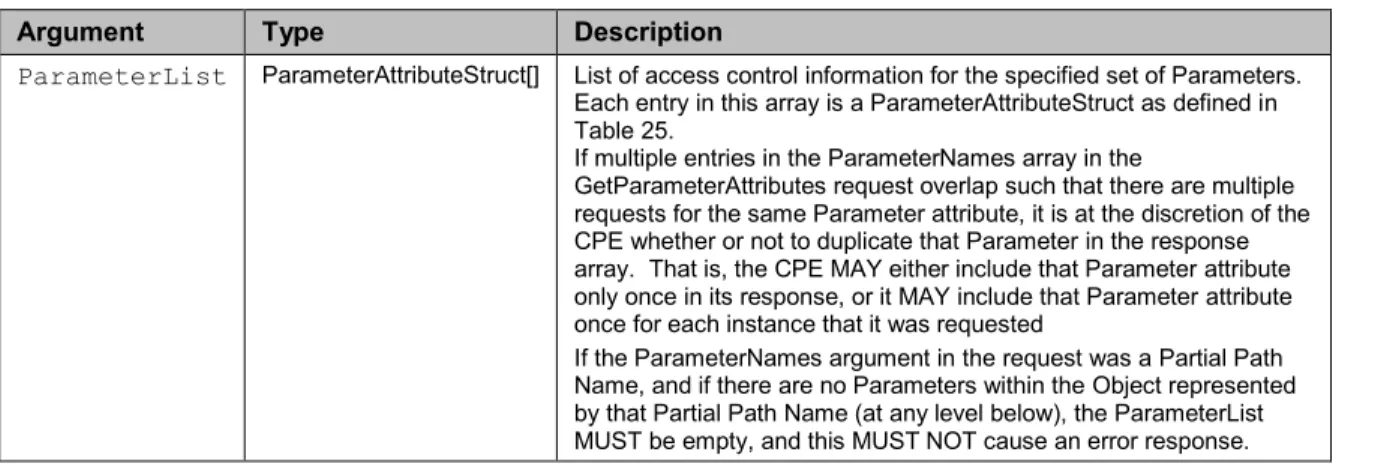
Table 27 – GetParameterAttributesResponse arguments ... 88
Table 28 – ParameterAttributeStruct definition ... 89
Table 29 – AddObject arguments ... 92
Table 30 – AddObjectResponse arguments ... 92
Table 31 – DeleteObject arguments ... 94
Table 32 – DeleteObjectResponse arguments ... 94
Table 33 – Download arguments ... 96
Table 34 – DownloadResponse arguments ... 100
Table 35 – Reboot arguments ... 101
Table 36 – RebootResponse arguments ... 101
Table 37 – Inform arguments ... 101
Table 38 – InformResponse arguments ... 102
Table 39 – DeviceIdStruct definition ... 103
Table 40 – EventStruct definition ... 103
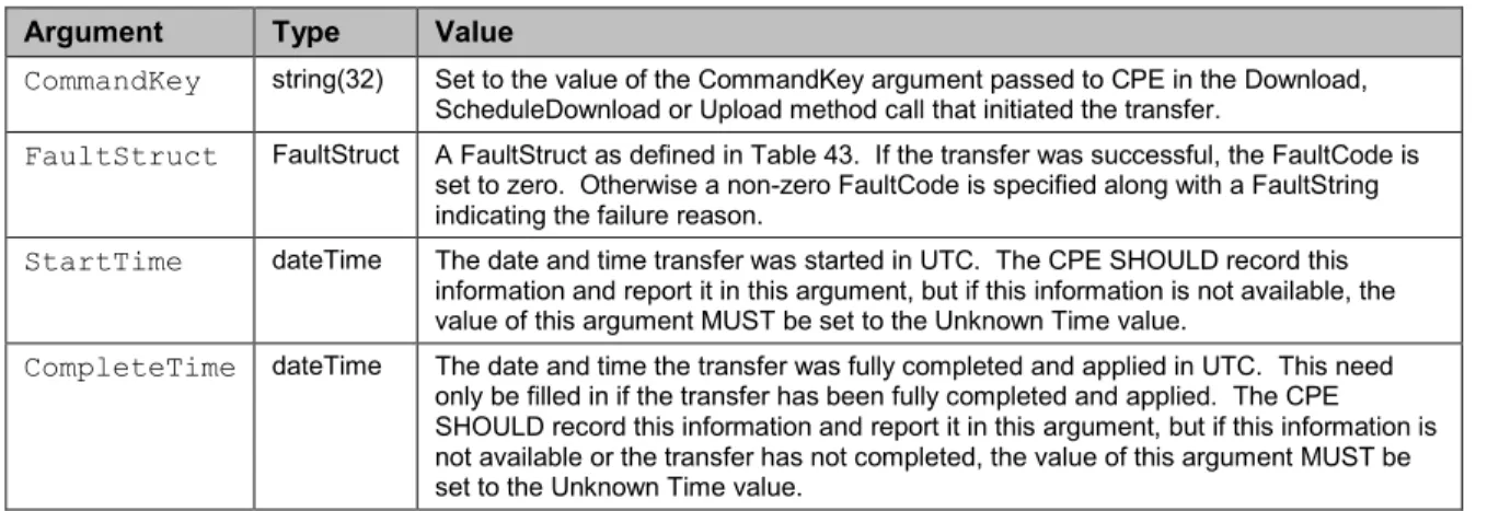
Table 41 – TransferComplete arguments ... 104
Table 42 – TransferCompleteResponse arguments ... 104
Table 43 – FaultStruct definition ... 105
Table 45 – AutonomousTransferCompleteResponse arguments ... 106
Table 46 – GetQueuedTransfers arguments ... 107
Table 47 – GetQueuedTransfersResponse arguments ... 107
Table 48 – QueuedTransferStruct definition ... 107
Table 49 – ScheduleInform arguments ... 108
Table 50 – ScheduleInformResponse arguments ... 108
Table 51 – SetVouchers arguments ... 108
Table 52 – SetVouchersResponse arguments ... 108
Table 53 – GetOptions arguments ... 109
Table 54 – GetOptionsResponse arguments ... 109
Table 55 – OptionStruct definition ... 109
Table 56 – Upload arguments ... 110
Table 57 – UploadResponse arguments ... 112
Table 58 – FactoryReset arguments ... 112
Table 59 – FactoryResetResponse arguments ... 112
Table 60 – GetAllQueuedTransfers arguments ... 113
Table 61 – GetAllQueuedTransfersResponse arguments ... 113
Table 62 – AllQueuedTransferStruct definition ... 113
Table 63 – ScheduleDownload arguments ... 115
Table 64 – ScheduleDownloadResponse arguments ... 116
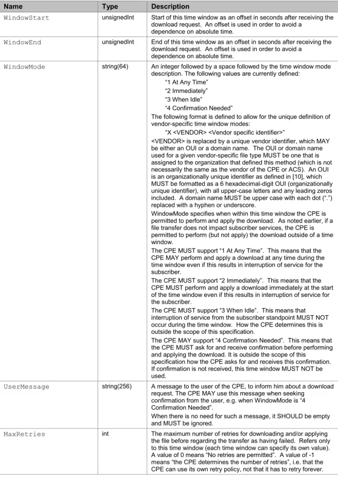
Table 65 – TimeWindowStruct definition ... 117
Table 66 – CancelTransfer arguments ... 118
Table 67 – CancelTransferResponse arguments ... 118
Table 68 – ChangeDUState Arguments ... 120
Table 69 – ChangeDUStateResponse Arguments ... 120
Table 70 – OperationStruct Types ... 120
Table 71 – InstallOpStruct Definition ... 120
Table 72 – UpdateOpStruct Definition ... 121
Table 73 – UninstallOpStruct Definition ... 121
Table 74 – Kicked arguments ... 122
Table 75 – KickedResponse arguments ... 122
Table 76 – RequestDownload arguments ... 122
Table 77 – RequestDownloadResponse arguments ... 123
Table 78 – ArgStruct definition ... 123
Table 79 – DUStateChangeComplete Arguments ... 124
Table 80 – OpResultStruct Definition ... 124
Table 81 – FaultStruct Definition ... 125
Table 82 – DUStateChangeCompleteResponse Arguments ... 126
Table 83 – AutonomousDUStateChangeComplete Arguments ... 127
Table 84 – AutonOpResultStruct Definition ... 127
Table 85 – FaultStruct Definition ... 128
Table 86 – AutonomousDUStateChangeCompleteResponse Arguments ... 129
Table 87 – Fault codes ... 129
Table 88 – Fault codes ... 131
Table 89 – CWMP XML Schema Versions ... 131
Table 91 – DeviceIdStruct definition ... 135
Table 92 – Recommended CGI Arguments for the kick URL ... 140
Table 93 – Signed package component summary ... 142
Table 94 – Signed package header format ... 143
Table 95 – Command format ... 143
Table 96 – Command Type summary ... 144
Table 97 – Value format for the extract and add commands ... 145
Table 98 – Value format for the remove commands ... 146
Table 99 – Value format for the move commands ... 147
Table 100 – Value format for the timeout commands ... 148
Table 101 – Timeout command definitions ... 149
Table 102 – Value format for the minimum and maximum version commands ... 150
Table 103 – Value format for the role command ... 151
Table 104 – Value format for the minimum storage commands ... 151
Table 105 – Value format for the required attributes command ... 152
Table 106 – Encapsulated Vendor-Specific Option-Data fields ... 160
Table 107 – Optional STUN attributes used in Binding Request messages ... 166
Table 108 – UDPLightweightNotification arguments ... 200
List of Figures
Figure 1 – Positioning in the End-to-End Architecture ... 18
Figure 2 – Protocol stack ... 26
Figure 3 – Session Example ... 69
Figure 4 – Example Option specification ... 135
Figure 5 – Example signed Voucher ... 135
Figure 6 – Sequence of events for the “kick” mechanism ... 140
Figure 7 – Signed package format ... 142
Figure 8 – Download state diagram used for timeout model ... 148
Figure 9 – Device-Gateway Association using DHCP Discover ... 158
Figure 10 – Device-Gateway Association Using DHCP Inform ... 159
Figure 11 – Binding discovery / maintenance from the primary source port ... 173
Figure 12 – Binding Request from secondary source port for binding timeout discovery ... 174
Figure 13 – Binding change notification authenticated by the ACS ... 174
Figure 14 – Binding change notification not authenticated by the ACS ... 175
Figure 15 – UDP Connection Request ... 175
Figure 16 – Proxy management terminology ... 180
Figure 17 – CPE Proxier and Proxied Device references ... 181
Figure 18 – XMPP Connection Request Message Sequence ... 187
Figure 19 – Connection Request: sent from ACS ... 193
Figure 20 – Successful Response to Connection Request: sent from CPE ... 193
Figure 21 – 503 Error Response to Connection Request from ACS ... 193
Figure 22 – Authentication Error Response to Connection Request from ACS ... 193
Figure 23 – Turnaround time ... 206
Figure 24 – Router supporting 6 Proxied Devices ... 208
Figure 25 – XMPP Deployment Option – Stateful Firewall ... 218
Figure 26 – Message flows when the CPE LAN device starts up normally ... 222
Figure 27 – Message flows when the CPE LAN device starts up normally ... 224
Executive Summary
A protocol for communication between a CPE and Auto-Configuration Server (ACS) that encompasses secure auto-configuration as well as other CPE management functions within a common framework.
1 Introduction
Note – Sections 1 and 2 of this document are introductory and do not define requirements of this protocol.
TR-069 describes the CPE WAN Management Protocol, intended for communication between a CPE and Auto-Configuration Server (ACS). The CPE WAN Management Protocol defines a mechanism that encompasses secure auto-configuration of a CPE, and also incorporates other CPE management functions into a common framework.
This document specifies the generic requirements of the management protocol methods which can be applied to any TR-069 CPE. Other documents specify the managed objects, or data models, for specific types of devices or services.
1.1 Functional Components
The CPE WAN Management Protocol is intended to support a variety of functionalities to manage a collection of CPE, including the following primary capabilities:
Auto-configuration and dynamic service provisioning
Software/firmware image management
Software module management
Status and performance monitoring
Diagnostics
1.1.1 Auto-Configuration and Dynamic Service Provisioning
The CPE WAN Management Protocol allows an ACS to provision a CPE or collection of CPE based on a variety of criteria.
The provisioning mechanism allows CPE provisioning at the time of initial connection to the broadband access network, and the ability to re-provision or re-configure at any subsequent time. This includes support for asynchronous ACS-initiated re-provisioning of a CPE.
The identification mechanisms included in the protocol allow CPE provisioning based either on the requirements of each specific CPE, or on collective criteria such as the CPE vendor, model, software version, or other criteria.
The protocol also provides optional tools to manage the CPE-specific components of optional applications or services for which an additional level of security is required to control, such as those involving payments. The mechanism for control of such
applications and services is the Software Module Management mechanism as defined in A.4.1.10 (ChangeDUState RPC), A.4.2.3 (DUStateChangeComplete RPC), and described in Appendix II / TR-157 Amendment 3 [29].
The provisioning mechanism allows straightforward future extension to allow provisioning of services and capabilities not yet included in this version of the specification.
1.1.2 Software/Firmware Image Management
The CPE WAN Management Protocol provides tools to manage downloading of CPE software/firmware image files. The protocol provides mechanisms for version
identification, file download initiation (ACS initiated downloads and optional CPE initiated downloads), and notification of the ACS of the success or failure of a file download.
1.1.3 Software Module Management
The CPE WAN Management Protocol enables an ACS to manage modular software and execution environments on a CPE. Capabilities provided include the ability to install, update, and uninstall software modules as well as notification to the ACS of success or failure of each action. The protocol also provides support to start and stop applications on the CPE, enable and disable execution environments, and inventory the software modules available on the device.
1.1.4 Status and Performance Monitoring
The CPE WAN Management Protocol provides support for a CPE to make available information that the ACS may use to monitor the CPE’s status and performance statistics. It also defines a set of mechanisms that allow the CPE to actively notify the ACS of changes to its state.
1.1.5 Diagnostics
The CPE WAN Management Protocol provides support for a CPE to make available information that the ACS may use to diagnose and resolve connectivity or service issues as well as the ability to execute defined diagnostic tests.
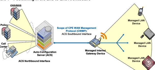
1.2 Positioning in the End-to-End Architecture
The ACS is a server that resides in the network and manages devices in or at the
subscriber premises. The CPE WAN Management Protocol may be used to manage both DSL B-NTs and other types of CPE, including stand-alone routers and LAN-side client devices. It is agnostic to the specific access medium utilized by the service provider, although it does depend on IP-layer connectivity having been established by the device.
Note – in the case of a B-NT, TR-046 [2] describes the overall framework for B-NT configuration, and TR-062 [3] and TR-044 [4] define the ATM layer and IP layer auto-configuration procedures. Other types of broadband CPE should make use of the protocols appropriate to their network architectures in order to obtain IP connectivity.
Note – where the CPE WAN Management Protocol is used to manage both a B-NT (or other Internet Gateway Device), and a LAN-side client device operating behind that B-NT (or other Internet Gateway Device), Annex F defines a mechanism to allow the ACS to associate the two so that they may be managed together.
Note –CPEImplementations might exist where the CPE WAN Management Protocol contains more than one CWMP Endpoint. Proxy management via the Virtual CWMP Device Mechanism is one such case.
Figure 1 – Positioning in the End-to-End Architecture OSS/BSS Call Center Policy Auto-Configuration Server (ACS) Managed Internet Gateway Device Managed LAN Device Managed LAN Device Managed LAN Device Scope of CPE WAN Management
Protocol (CWMP): ACS Southbound Interface
ACS Northbound Interface OSS/BSS Call Center Policy Auto-Configuration Server (ACS) Managed Internet Gateway Device Managed LAN Device Managed LAN Device Managed LAN Device Scope of CPE WAN Management
Protocol (CWMP): ACS Southbound Interface
ACS Northbound Interface
1.3 Security Goals
The CPE WAN Management Protocol is designed to provide a high degree of security. The security model is also designed to be scalable. It is intended to allow basic security to accommodate less robust CPE implementations, while allowing greater security for those that can support more advanced security mechanisms. In general terms, the security goals of the CPE WAN Management Protocol are as follows:
Prevent tampering with the management functions of a CPE or ACS, or the transactions that take place between a CPE and ACS.
Provide confidentiality for the transactions that take place between a CPE and ACS.
Allow appropriate authentication for each type of transaction.
Prevent theft of service. 1.4 Architectural Goals
The protocol is intended to provide flexibility in the connectivity model. The protocol is intended to provide the following:
Allow both CPE and ACS initiated connection establishment, avoiding the need for a persistent connection to be maintained between each CPE and an ACS.
The functional interactions between the ACS and CPE should be independent of which end initiated the establishment of the connection. In particular, even where ACS initiated connectivity is not supported, all ACS initiated transactions should be able to take place over a connection initiated by the CPE.
Allow one or more ACSs to serve a population of CPE, which may be associated with one or more service providers.
Provide mechanisms for a CPE to discover the appropriate ACS for a given service provider.
Provide mechanisms to allow an ACS to securely identify a CPE and associate it with a user/customer. Processes to support such association should support models that incorporate user interaction as well as those that are fully automatic.
The protocol is intended to allow an ACS access to control and monitor various
Parameters associated with a CPE. The mechanisms provided to access these Parameters are designed with the following premises:
Different CPE may have differing capability levels, implementing different subsets of optional functionality. Additionally, an ACS may manage a range of different device types delivering a range of different services. As a result, an ACS must be able to discover the capabilities of a particular CPE.
An ACS must be able to control and monitor the current configuration of a CPE.
Other control entities besides an ACS may be able to control some Parameters of a CPE’s configuration (e.g., via LAN-side auto-configuration). As a result, the protocol must allow an ACS to account for external changes to a CPE’s configuration. The ACS should also be able to control which configuration Parameters can be controlled via means other than by the ACS.
The protocol should allow vendor-specific Parameters to be defined and accessed. The protocol is intended to minimize implementation complexity, while providing flexibility in trading off complexity vs. functionality. The protocol incorporates a number of optional components that come into play only if specific functionality is required. The protocol also incorporates existing standards where appropriate, allowing leverage of off-the-shelf implementations.
The protocol is intended to be agnostic to the underlying access network.
The protocol is also designed to be extensible. It includes mechanisms to support future extensions to the standard, as well as explicit mechanisms for vendor-specific extensions. 1.5 Assumptions
Some assumptions made in defining the CPE WAN Management Protocol are listed below:
All CPE regardless of type (bridge1, router, or other) obtain an IP address in order to communicate with an ACS.
A CWMP Endpoint can interact with a single ACS at a time. At any time, a CWMP Endpoint is aware of exactly one ACS with which it can connect. (Note: a collection of ACSs behind a load balancer is considered a single ACS for the purposes of this document.)
1 In the case of a bridge, the CPE must establish IP-layer connectivity specifically for management communication.
The mechanism used to establish this connectivity would depend on the specific network architecture. For example, a DSL bridge may connect using IPoE with DHCP for address allocation, or may connect using PPPoE.
1.6 Terminology
The following terminology is used throughout the series of documents defining the CPE WAN Management Protocol.
ACS Auto-Configuration Server. This is a component in the broadband network responsible for auto-configuration of the CPE for advanced services.
Action An explicitly triggered transition in the Software Module state model; e.g. Install, Update, Uninstall, Start, Stop, etc. (see Appendix II/TR-157 [29])
Applied A change to the CPE’s configuration has been Applied when the CPE
has stopped using the previous configuration and begun using the new configuration.
B-NT Broadband-Network Termination. A specific type of Broadband CPE
used in DSL networks.
Committed A change to the CPE’s configuration has been Committed when the change has been fully validated, the new configuration appears in the configuration Data Model for subsequent ACS operations to act on, and the change will definitely be Applied in the future, as required by the protocol specification.
Connection Request
The ACS action of requesting a CPE to start a CWMPSession, as defined in “3.2.2 ACS Connection Initiation.”
CPE Customer Premises Equipment; refers to a TR-069-compliant device and therefore covers both Internet Gateway Devices and LAN-side end devices. A CPE contains at least one CWMP Endpoint.
CPE Proxier A CPE that is capable of proxying the communication between an ACS
and a ProxiedDevice. There are two strategies for proxy management:
Virtual CWMP Device Mechanism and Embedded Object Mechanism.
CR-Aware Standby
A CPE in CR-Aware Standby is able to receive Connection Requests and to accept or reject them.
CWMP CPE WAN Management Protocol (the subject of this standard).
CWMP Endpoint
A CWMP termination point used by a CPE for Session communication with the ACS. This term is used interchangeably with CPE unless specifically defining behavior where a CPE supports multiple CWMP Endpoints
Data Model A hierarchical set of Parameters that define the managed Objects accessible via TR-069 for a particular Device or service.
Deployment Unit
An entity that can be individually deployed on the Execution
Environment. A Deployment Unit can consist of functional Execution Units and/or configuration files and/or other resources.
DT Instance Device Type Schema instance document. This is an XML document that conforms to the DT Schema and to any additional rules specified in or referenced by the DT Schema.
DT Schema Device Type Schema. This is the XML Schema that is used for
describing a Device’s supported data model (see Annex B/TR-106 [13]).
Embedded Object Mechanism
A proxy management strategy where the CPEProxier embeds the details of the Proxied Device within the Data Model. The Proxied Device will appear to be integrated into the CPEProxier.
Event An indication that something of interest has happened that requires the
CPE to notify the ACS.
Execution Environment
A software platform that enables the dynamic loading and unloading of
Software Modules. Typical examples include Linux, OSGi, .NET, and Java ME. Some Execution Environments enable the sharing of resources amongst modules.
Execution Unit
A functional entity that, once started, initiates processes to perform tasks or provide services, until it is stopped. Execution Units are deployed by
Deployment Units. The following list of concepts could be considered an Execution Unit: services, scripts, software components, libraries, etc.
Forced Inform Parameter
A Parameter whose definition requires it to be included with every Inform RPC.
Instance Alias
A writeable string that uniquely identifies an instance within a Multi-Instance Object.
Instance Identifier
A value that uniquely identifies an instance within a Multi-Instance Object. It is either an Instance Number or an Instance Alias.
Instance Number
A read-only positive integer (>=1) that uniquely identifies an instance within a Multi-Instance Object.
Internet Gateway Device
A CPE device, typically a broadband router, that acts as a gateway between the WAN and the LAN.
Multi-Instance Object
An Object that can have multiple instances, all of which have the same structure and are located at the same level within the name hierarchy. Each instance is identified by an Instance Identifier.
Object An internal node in the name hierarchy, i.e., a node that can have Object or Parameter children. An Object name is a Path Name.
Parameter A name-value pair that represents part of a CPE’s configuration or status. A Parameter name is a Path Name.
Path Name A name that has a hierarchical structure similar to files in a directory, with each level separated by a “.” (dot). References an Object or a
Partial Path Name
A Path Name that ends with a “.” (dot). References an Object and represents a subset of the name hierarchy.
Periodic Contact
A time when the CPE has to send a Periodic Inform.
Periodic Inform
An Inform message including the “2 PERIODIC” event.
Proxied Device
An endpoint that communicates indirectly with an ACS via a CPE Proxier.
RPC Remote Procedure Call.
Scheduled Contact
A specific time, resulting from a previous ACS request, when the CPE
has to send an Inform. This does not include Periodic Informs.
Seen Missing A CPE has been Seen Missing by the ACS when that CPE has missed a
Periodic Contact or Scheduled Contact or when the ACS has failed to get a response to a Connection Request. A CPE cannot determine whether it has been Seen Missing.
Session A contiguous sequence of CWMP Transactions between a CWMP Endpoint and an ACS. Note that a Session may span multiple TCP connections.
Software Module
The common term for all software (other than firmware) that will be installed on an Execution Environment, including the concepts of
Deployment Units and Execution Units.
STB Set Top Box. This CPE contains Audio and Video decoders and is intended to be connected to Analog TV and / or Home Theaters.
Timer-Aware Standby
A CPE in Timer-Aware Standby is able to wake up to handle Periodic Contacts and Scheduled Contacts. Partial Timer-Aware Standby is possible (CPE waking up only for Scheduled Contacts, for example).
Transaction A message exchange between a CWMP Endpoint and an ACS consisting of a single request followed by a single response, initiated either by the
CPE or ACS.
Virtual CWMP Device Mechanism
A proxy management strategy where the CPEProxier creates a virtual CWMP environment for the Proxied Device. The CPE Proxier provides a separate CWMP Endpoint for each such Proxied Device, which will therefore appear and be managed like a standalone CWMP enabled CPE.
VoIP Endpoint
A Voice over IP CPE that acts as the initiation/termination point for VoIP calls. Examples of Endpoints include VoIP phones and analog terminal adapters (ATAs).
1.7 Abbreviations
This Technical Report defines the following abbreviations: ACL Access control list
ACS Auto-Configuration Server
ADSL Asymmetric Digital Subscriber Line AES Advanced Encryption Standard
ASCII American Standard Code for Information Interchange ATA Analog terminal adapter
ATM Asynchronous Transfer Mode BOOTP Boot Strap Protocol
CGI Common Gateway Interface CN Common Name
CPE Customer Premise Equipment CR Connection Request
CSRF Cross-site request forgery
CWMP CPE WAN Management Protocol DHCP Dynamic Host Configuration Protocol DNS Domain Name System
DSL Digital Subscriber Line
DSM-CC Digital storage media command and control DT Device Type
DU Deployment Unit EE Execution Environment EU Execution Unit
FLUTE File Delivery over Unidirectional Transport FTP File transfer Protocol
HMAC Hash-based Message Authentication Code HTML Hypertext Markup Language
HTTP Hypertext Transfer Protocol
HTTPS Hypertext Transfer Protocol over Secure Socket Layer IANA Internet Assigned Numbers Authority
ID Identifier
IP Internet Protocol
IPv6 Internet Protocol version 6
ISO International Organization for Standardization LAN Local Area Network
LSB Least significant bit
MD5 Message-Digest algorithm 5 NAT Network Address Translation NTP Network Time Protocol NT Network Termination
OSGi OSGi Alliance (former Open Services Gateway initiative) OUI Organizationally Unique Identifier
PKCS Public Key Cryptography Standards QoS Quality of Service
RFC Request for Proposal RPC Remote Procedure Call
RSA Rivest, Shamir and Adleman (crypto system) SASL Simple Authentication and Security Layer
SFTP SSH File Transfer Protocol SHA1 Secure Hash Algorithm 1
SNMP Simple Network Management Protocol SNTP Simple Network Time Protocol
SOAP Simple Object Access Protocol SSH Secure Shell
SSL Secure Socket Layer STB Set Top Box
STUN Session Traversal Utilities for NAT TCP Transmission Control Protocol TFTP Tiny File transfer Protocol TLS Transport Layer Security TLV Type length value TR Technical Report TTL Time to Live TV Television
UDP User Datagram Protocol UPnP Universal Plug and Play
UPnP DM Universal Plug and Play Device Management UPnP IGD Universal Plug and Play Internet Gateway Device URI Uniform Resource Identifier
URL Universal Resource Locator URN Uniform Resource Name UTC Coordinated Universal Time
UTF Universal Multiple-Octet Coded Character Set Transformation Format UUID Universally Unique Identifier
VoIP Voice over Internet Protocol WAN Wide Area Network
XML Extensible Markup Language
XMPP Extensible Messaging and Presence Protocol XSD XML Schema
XSS Cross-Site Scripting 1.8 Document Conventions
The key words "MUST", "MUST NOT", "REQUIRED", "SHALL", "SHALL NOT", "SHOULD", "SHOULD NOT", "RECOMMENDED", "MAY", and "OPTIONAL" in this document are to be interpreted as described in [1].
The key word “DEPRECATED” refers to a protocol feature, e.g. an RPC Method or Event Type, that is defined and valid in the current version of the standard but is not strictly necessary, e.g. because another more powerful feature has been defined. Such features SHOULD NOT be used; they might be removed from the next major version of the protocol.
The key word “OBSOLETED” refers to a protocol feature, e.g. an RPC Method or Event Type, that meets the requirements for being DEPRECATED, and in addition is obsolete. Such protocol features MUST NOT be used; they might be removed from a later minor
version of the protocol, without this being regarded as breaking backwards compatability rules.
2 Architecture
2.1 Protocol Components
The CPE WAN Management Protocol comprises several components that are unique to this protocol, and makes use of several standard protocols. The protocol stack defined by the CPE WAN Management Protocol is shown in Figure 2. A brief description of each layer is provided in Table 1. Note that the CPE and ACS must adhere to the requirements of the underlying standard protocols unless otherwise specified.
Figure 2 – Protocol stack
CPE/ACS Management Application RPC Methods
SOAP HTTP SSL/TLS
TCP/IP
Table 1 – Protocol layer summary
Layer Description
CPE/ACS Application The application uses the CPE WAN Management Protocol on the CPE and ACS, respectively. The application is locally defined and not specified as part of the CPE WAN Management Protocol.
RPC Methods The specific RPC methods that are defined by the CPE WAN Management Protocol. These methods are specified in Annex A.
SOAP A standard XML-based syntax used here to encode remote procedure calls. Specifically SOAP 1.1, as specified in [9].
HTTP HTTP 1.1, as specified in [6].
TLS The standard Internet transport layer security protocol. Specifically, TLS 1.2 (Transport Layer Security) as defined in [11] (or a later version). Note that previous versions of this specification referenced SSL 3.0 and TLS 1.0.
2.2 Security Mechanisms
The CPE WAN Management Protocol is designed to allow a high degree of security in the interactions that use it. The CPE WAN Management Protocol is designed to prevent tampering with the transactions that take place between a CPE and ACS, provide
confidentiality for these transactions, and allow various levels of authentication. The following security mechanisms are incorporated in this protocol:
The protocol supports the use of TLS for communications transport between CPE and ACS. This provides transaction confidentiality, data integrity, and allows certificate-based authentication between the CPE and ACS.
The HTTP layer provides an alternative means of CPE and ACS authentication based on shared secrets. Note that the protocol does not specify how the shared secrets are learned by the CPE and ACS.
2.3 Architectural Components 2.3.1 Parameters
The RPC Method Specification (see Annex A) defines a generic mechanism by which an ACS can read or write Parameters to configure a CPE and monitor CPE status and statistics. Parameters for various classes of CPE are defined in separate documents. At the time of writing the following standards define TR-069 data models.
TR-098: Internet Gateway Device Data Model for TR-069 [24]
TR-104: Provisioning Parameters for VoIP CPE [25]
TR-135: Data Model for a TR-069 Enabled STB [26]
TR-140: TR-069 Data Model for Storage Service Enabled Devices [27]
TR-143: Enabling Network Throughput Performance Tests and Statistical Monitoring [28]
TR-157: Component Objects for CWMP [29]
TR-181: Device Data Model for TR-069 [31] and [32]
TR-196: Femto Access Point Service Data Model [30]
Each Parameter consists of a name-value pair. The name identifies the particular Parameter. The value of a Parameter may be one of several defined data types (see TR-106 [13]).
Parameters may be defined as read-only or read-write. Read-only Parameters may be used to allow an ACS to determine specific CPE characteristics, observe the current state of the CPE, or collect statistics. Writeable Parameters allow an ACS to customize various aspects of the CPE’s operation. All writeable Parameters must also be readable although those that contain confidential user information, e.g. passwords, may return empty values when read (this is specified in the corresponding data model definition). The value of some writeable Parameters may be independently modifiable through means
other than the interface defined in this specification (e.g., some Parameters may also be modified via a LAN side auto-configuration protocol).
Because other protocols (as well as subscriber action) may independently modify the device configuration, the ACS cannot assume that it is the only entity modifying device configuration. Additionally, it is possible that a LAN-side mechanism could alter device configuration in such a way that it contravenes the intended ACS-supplied configuration. Care should be taken in the implementation of both WAN and LAN-side
auto-configuration mechanisms, as well as subscriber-facing interfaces, to limit the instances of such an occurrence.
The protocol supports a discovery mechanism that allows an ACS to determine what Parameters a particular CPE supports, allowing the definition of optional Parameters as well as supporting straightforward addition of future standard Parameters.
The protocol also includes an extensibility mechanism that allows use of vendor-specific Parameters in addition to those defined in this specification.
2.3.2 File Transfers
The RPC Method Specification (see Annex A) defines mechanisms to facilitate file transfers for a variety of purposes, such as downloading firmware upgrades or vendor-specific configuration files, (optionally) installing or updating software modules, and (optionally) uploading configuration or log files from the device.
File transfers can be performed by means of Unicast or (for downloads) Multicast transport protocols. Unicast protocols include HTTP/HTTPS, FTP, SFTP and TFTP. Multicast protocols include FLUTE and DSM-CC. Support for HTTP/HTTPS is mandatory, and protocols other than those listed here can be supported.
When a file transfer is initiated by the ACS via any of the method calls that can cause a file transfer, the CPE is provided with the location of the file (or possibly files in the case of a software module installation or update) to be transferred, or details of the Multicast group to join (for Multicast downloads). The CPE then performs the transfer(s), and notifies the ACS of success or failure.
Downloads may be optionally initiated by a CPE. In this case, the CPE first requests a download of a particular file type from the ACS. The ACS may then respond by initiating the download following the same steps as an ACS-initiated download. File transfers may also be optionally initiated by an external event, e.g. a Multicast firmware availability announcement or user-initiated software module updates. In this case, the CPE performs the transfer autonomously, and notifies the ACS of the success or failure.
2.3.3 CPE Initiated Sessions
The RPC Method Specification (see Annex A) defines a mechanism that allows a CPE to inform a corresponding ACS of various conditions, and to ensure that CPE-to-ACS communication will occur with some minimum frequency.
This includes mechanisms to establish communication upon initial CPE installation in order to ‘bootstrap’ initial customized Parameters into the CPE. It also includes a
mechanism to establish periodic communication with the ACS on an ongoing basis, or when events occur that must be reported to the ACS (such as when the broadband IP address of the CPE changes).
In each case, when communication is established the CPE identifies itself uniquely via manufacturer and serial number information (and optional product class identifier) so that the ACS knows which CPE it is communicating with and can respond in an appropriate way.
2.3.4 Asynchronous ACS Initiated Sessions
An important aspect of service auto-configuration is the ability for the ACS to inform the CPE of a configuration change asynchronously. This allows the auto-configuration mechanism to be used for services that require near-real-time reconfiguration of the CPE. For example, this may be used to provide an end-user with immediate access to a service or feature they have subscribed to, without waiting for the next periodic contact.
The CPE WAN Management Protocol incorporates a mechanism for the ACS to issue a Connection Request to the CPE at any time, instructing it to establish a communication Session with the ACS.
While the CPE WAN Management Protocol also allows polling by the CPE in lieu of ACS-initiated connections, the CPE WAN Management Protocol does not rely on polling or establishment of persistent connections from the CPE to provide asynchronous
notification.
The basic mechanism defined in the CPE WAN Management Protocol to enable
asynchronous ACS initiated communication assumes direct IP addressability of the CPE from the ACS. An alternative mechanism is defined in Annex K, which accommodates CPE that are not directly addressable by the ACS.
3 Procedures and Requirements
This Section, along with the Annexes referenced in this Section, defines the normative requirements of the CPE WAN Management Protocol.
This Section also references a number of standards and other specifications that form part of the CPE WAN Management Protocol. Unless otherwise specified, the CPE and ACS MUST adhere to the requirements of these referenced specifications.
3.1 ACS Discovery
The CPE WAN Management Protocol defines the following mechanisms that MAY be used by a CPE to discover the address of its associated ACS:
1. The CPE MAY be configured locally with the URL of the ACS for each CWMP Endpoint. For example, this MAY be done via a LAN-side CPE auto-configuration protocol. If necessary, the CPE would use DNS to resolve the IP address of the ACS from the host name component of the URL.
2. As part of the IP layer auto-configuration, a DHCP server on the access network MAY be configured to include the ACS URL as a DHCP option [14] / [22] / [35]. If necessary, the CPE would use DNS to resolve the IP address of the ACS from the host name component of the URL. In this case additional DHCP options MAY be used to set:
The ProvisioningCode, which MAY be used to indicate the primary service provider and other provisioning information to the ACS.
The CWMPRetryMinimumWaitInterval, which MAY be used to set the initial value of the CWMP session retry minimum wait interval, as specified in Section 3.2.1.1.
The CWMPRetryIntervalMultiplier, which MAY be used to set the initial value of the CWMP session retry interval multiplier, as specified in Section 3.2.1.1.
A CPE identifies itself to the DHCP server as supporting this method by including the string “dslforum.org” (all lower case) anywhere in the DHCPv4 Vendor Class
Identifier (option 60), in the DHCPv4 V-I Vendor Class Option (option 124) or in a DHCPv6 Vendor Class (option 16) vendor-class-data item.
The CPE MAY include either DHCPv4 option 43 or DHCPv4 option 125 (not both) in a DHCPv4 parameter request list (option 55) in order to indicate support for and to request option 43 or option 125. If the CPE does not use option 55 in this way, the server can assume that it supports and requests option 43 (not option 125). Similarly, the CPE MAY include DHCPv6 option 17 in a DHCPv6 Option Request Option (option 6).
The CPE MAY use the values received from the DHCP server in the Vendor Specific Information (DHCPv4 option 43 / DHCPv4 option 125 / DHCPv6 option 17) to set the corresponding Parameters as listed in Table 2. If both DHCPv4 options are received, the CPE MUST use the DHCP option that it included in the DHCPv4 parameter request list (option 55); unless it did not use option 55, in which case the
CPE MUST use the DHCPv4 option 43 values. If both DHCPv4 and DHCPv6 options are received, the CPE MUST use the DHCPv6 option over the DHCPv4 option. This DHCP option is encoded as a list of one or more Encapsulated Vendor-Specific Options in the format defined in [14] / [22] / [35]. This list MAY include other vendor-specific options in addition to those listed here.
DHCP messages that include IANA Enterprise Numbers, i.e. DHCPv4 options 124 / 125 and DHCPv6 options 16 / 17, MUST use the Broadband Forum IANA Enterprise Number, which is 3561 decimal (the “ADSL Forum” entry in the IANA Private Enterprise Numbers registry [18]).
If the CPE obtained an ACS URL through DHCP and it cannot reach the ACS, the CPE MUST use DHCP to re-discover the ACS URL. The CPE MUST consider the ACS unreachable if it cannot establish a TCP connection to it for 300 seconds at each of the IP addresses to which the ACS URL resolves. If the CPE does not receive a DHCP reply, it MUST attempt to retry according to [20] / [35].
When the CPE needs to contact the ACS, it MUST use the DHCP discovery mechanism in the following scenarios:
If the CPE has an empty value for the ManagementServer.URL Parameter, or
If the CPE is unable to contact the ACS and the CPE originally (the first
successful time after the most recent factory reset) obtained its ACS URL through DHCP.
This behavior enables the CPE to go back to the use of DHCP for finding the ACS if an ACS URL had not been pre-configured in the CPE. For example, this can handle the situation of setting an incorrect ACS URL on the CPE. This behavior is not meant as an ACS failover mechanism.
The CPE MUST remember the mechanism it used to locate the ACS after each factory reset. If the CPE did not use DHCP to discover the ACS URL, then it SHOULD NOT fall back to using DHCP for ACS discovery. If the CPE originally used DHCP for ACS discovery, then when it fails to contact the ACS, it MUST perform re-discovery via DHCP. The last requirement holds even if the ACS URL has been subsequently set through a non-DHCP mechanism.
Table 2 – Encapsulated Vendor Specific Options Encapsulated
Option Specific Option number Encapsulated Vendor- Parameter
2 DHCPv4 Option 43 DHCPv4 Option 125 DHCPv6 Option 17
URL of the ACS 1 11 1 ManagementServer.URL Provisioning code 2 12 2 DeviceInfo.ProvisioningCode CWMP retry
mini-mum wait interval
3 13 3 ManagementServer.CWMPRetryMinimumWait-Interval CWMP retry interval multiplier 4 14 4 ManagementServer.CWMPRetryIntervalMultiplier 2 As defined in [24], [31], and [32].
All the encapsulated option values MUST be represented as strings and MUST be valid values for their corresponding Parameters. The specified URL MUST be an absolute URL. The encapsulated option values MUST NOT be null terminated. If the CPE receives an encapsulated option value that is null terminated, the CPE MUST accept the value provided, and MUST NOT interpret the null character as part of the value.
3. The CPE MAY have a default ACS URL that it MAY use if no other URL is provided to it.
The ACS URL MUST be in the form of a valid HTTP or HTTPS URL [6]. Use of an HTTPS URL indicates that the CPE MUST establish an SSL or TLS connection to the ACS.
Once the CPE has established a connection to the ACS via a CWMP Endpoint, the ACS MAY at any time modify the ACS URL Parameter stored within the CPE (Management-Server.URL, as defined in [24], [31], and [32]). Once modified, the CPE MUST use the modified URL for all subsequent connections to the ACS.
The “host” portion of the ACS URL is used by the CPE for validating the certificate from the ACS when using certificate-based authentication. Because this relies on the accuracy of the ACS URL, the overall security of this protocol is dependent on the security of the ACS URL.
The CPE SHOULD restrict the ability to locally configure the ACS URL to mechanisms that require strict security. The CPE MAY further restrict the ability to locally set the ACS URL to initial setup only, preventing further local configuration once the initial connection to an ACS has successfully been established such that only its existing ACS is permitted subsequently to change this URL.
The use of DHCP for configuration of the ACS URL SHOULD be limited to situations in which the security of the link between the DHCP server and the CPE can be assured by the service provider. Since DHCP does not itself incorporate a security mechanism, other means of ensuring this security SHOULD be provided.
The ACS URL MAY contain a DNS hostname or an IP address. When resolving the ACS hostname, the DNS server might return multiple IP addresses. In this case, the CPE SHOULD randomly choose an IP address from the list. When the CPE is unable to reach the ACS, it SHOULD randomly select a different IP address from the list and attempt to contact the ACS at the new IP address. This behavior ensures that CPEs will balance their requests between different ACSs if multiple IP addresses represent different ACSs. The CPE MUST NOT cache the DNS server response beyond the duration of time to live (TTL) returned by DNS server unless it cannot contact the DNS server for an update. This behavior is required by DNS RFC 1034 [5] and provides an opportunity for the DNS server to update stale data.
It is further RECOMMENDED that the CPE implements affinity to a particular ACS IP address. Affinity to a given IP address means that the CPE will attempt to use the same IP address for as long as it can contact the ACS at this address. This creates a more stable system and can allow the ACS to perform better due to better caching. To
implement the affinity the CPE SHOULD store to persistent storage the last successfully used IP address and the list of IP addresses from which it was selected. The CPE
SHOULD continue to perform DNS queries as normal, but SHOULD continue using the same IP address for as long as it can contact the ACS and for as long as the list of IP addresses returned by the DNS does not change. The CPE SHOULD select a new IP address whenever the list of IP addresses changes or when it cannot contact the ACS. This provides an opportunity for service providers to reconfigure their network. Port 7547 has been assigned by IANA for the CPE WAN Management Protocol (see [17]), and the ACS MAY use this port in its URL.
3.2 Connection Establishment 3.2.1 CPE Connection Initiation
The CPE MAY at any time initiate a connection to the ACS via a CWMP Endpoint using the pre-determined ACS address (see Section 3.1). A CPE MUST establish a connection to the ACS and issue the Inform RPC method (following the procedures described in Section 3.7.1.1) under the following conditions:
The first time the CPE establishes a connection to the access network on initial installation
On power-up or reset
Once every ManagementServer.PeriodicInformInterval (for example, every 24 hours)
When so instructed by the optional ScheduleInform method
Whenever the CPE receives a valid Connection Request from an ACS (see Section 3.2.2)
Whenever the URL of the ACS changes
Whenever a Parameter is modified that is required to initiate an Inform on change.
Whenever the value of a Parameter that the ACS has marked for “Active notification” via the SetParameterAttributes method is modified by an external cause (a cause other than the ACS itself). Parameter changes made by the ACS itself via SetParameterValues MUST NOT cause a new Session to be initiated. If a Parameter is modified more than once before the CPE is able to initiate a
Session to perform the notification, the CPE MUST perform only one notification. If a Parameter is modified by an external cause while a Session is in progress, the change causes a new Session to be established after the current Session is
terminated (it MUST NOT affect the current Session).
In order to avoid excessive traffic to the ACS, a CPE MAY place a locally specified limit on the frequency of Parameter change notifications. This limit SHOULD be defined so that it is exceeded only in unusual circumstances. If this limit is exceeded, the CPE MAY delay by a locally specified amount initiation of a Session to notify the ACS. After this delay, the CPE MUST initiate a Session to
the ACS and indicate all relevant Parameter changes (those Parameters that have been marked for notification) that have occurred since the last such notification.
Whenever a download or upload completes (either successfully or
unsuccessfully), provided that CPE policy indicates that the ACS needs to be notified of the download or upload completion.
The ACS MUST always be notified of the completion of downloads or uploads that were specifically requested by the ACS.
CPE policy MUST determine whether to notify the ACS of the completion of downloads or uploads that were not specifically requested by the ACS. Note – this CPE policy is remotely configurable via the parameters defined within the
ManagementServer.AutonomousTransferCompletePolicy object. For example, the CPE might be configured to notify the ACS only if a download or upload (not requested by the ACS) was not completed successfully.
Whenever an unsuccessfully terminated Session is retried according to the session retry policy specified in Section 3.2.1.1.
The CPE MUST NOT maintain an open connection to the ACS when no more
outstanding messages exist on the CPE or ACS. Refer to Section 3.7.1.4 for details of CPE Session termination criteria.
3.2.1.1 Session Retry Policy
A CPE MUST retry failed Sessions to attempt to redeliver events that it has previously failed to deliver and to allow the ACS to make additional requests in a timely fashion. Section 3.7.1.5 details the rules for successful event delivery, for retrying event delivery, and for discarding events after failing to deliver them. The CPE MUST keep track of the number of times it has attempted to retry a failed Session.
If the CPE fails to establish a Session, this might be because the CPE supports CPE WAN Management Protocol v1.1 (or later) and the ACS supports only v1.0. If this situation is suspected (see Section 3.7.2.1), the CPE MUST revert to v1.0 when retrying the failed Session.
A CPE MUST retry a failed Session after waiting for an interval of time specified in Table 3 or when a new event occurs, whichever comes first. The CPE MUST choose the wait interval by randomly selecting a number of seconds from a range given by the post-reboot session retry count. When retrying a failed Session after an intervening post-reboot, the CPE MUST reset the wait intervals it chooses from as though it were making its first session retry attempt. In other words, if a Session is retried when a new event other than BOOT occurs, it does not reset the wait interval, although the continued occurrence of new events might cause Sessions to be initiated more frequently than shown in the table. Regardless of the reason a previous Session failed or the condition prompting session retry, the CPE MUST communicate to the ACS the session retry count.
The wait interval range is controlled by two Parameters, the minimum wait interval and the interval multiplier, each of which corresponds to a data model Parameter, and which are described in the table below.
Descriptive Name Symbol3 Default4 Data Model Parameter Name
Minimum wait interval m 5 seconds ManagementServer.CWMPRetryMinimumWaitInterval Interval multiplier k 2000 ManagementServer.CWMPRetryIntervalMultiplier
The factory default values of these Parameters MUST be the values that were hard-coded in previous versions of the CPE WAN Management Protocol, i.e. the values from the Default column. These values MAY be overridden by values obtained via DHCP, as explained in Section 3.1. They MAY also be changed by the ACS at any time.
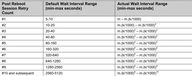
Beginning with the tenth post-reboot session retry attempt, the CPE MUST choose from the fixed maximum range shown in Table 3. The CPE MUST continue to retry a failed Session until it is successfully terminated or until the rules defined in the “Retry/Discard Policy” column within Table 8 take precedence. Once a Session terminates successfully, the CPE MUST reset the session retry count to zero and no longer apply session retry policy to determine when to initiate the next Session.
Table 3 – Session Retry Wait Intervals Post Reboot
Session Retry Count
Default Wait Interval Range
(min-max seconds) Actual Wait Interval Range (min-max seconds)
#1 5-10 m – m.(k/1000) #2 10-20 m.(k/1000) – m.(k/1000)2 #3 20-40 m.(k/1000)2– m.(k/1000)3 #4 40-80 m.(k/1000)3– m.(k/1000)4 #5 80-160 m.(k/1000)4– m.(k/1000)5 #6 160-320 m.(k/1000)5– m.(k/1000)6 #7 320-640 m.(k/1000)6– m.(k/1000)7 #8 640-1280 m.(k/1000)7– m.(k/1000)8 #9 1280-2560 m.(k/1000)8– m.(k/1000)9 #10 and subsequent 2560-5120 m.(k/1000)9– m.(k/1000)10
3.2.1.2 Use of random source port
Each time the CPE first connects to the ACS after rebooting, it SHOULD use a different ephemeral TCP source port in order to avoid the possibility of reusing the same port that it used last time. Reuse of the same port could cause the ACS to reject the connection if the elapsed time since the previous connection is less than the ACS’s configured TCP TIME_WAIT value.
In order to minimize the probability that the same ephemeral port number is used on successive occasions, the port SHOULD be selected using a strong randomization mechanism.
3 These symbols are used in Table 3.
3.2.2 ACS Connection Initiation
The ACS MAY at any time request that a CWMP Endpoint initiate a connection to the ACS using the Connection Request mechanism. Support for this mechanism is
REQUIRED in a CPE, and is RECOMMENDED in an ACS.
This mechanism relies on the CPE being reachable by the ACS. If the CPE is behind a firewall or if there is a NAT device between the ACS and CPE, the ACS might not be able to access the CPE at all. Annex K defines a mechanism that allows an ACS to contact a CPE that is not directly reachable by the ACS.
This mechanism relies on the ACS having had at least one prior communication with the CWMP Endpoint in a CPE-initiated interaction. During this interaction, if the ACS wishes to allow future ACS-initiated transactions, it would use the value of the
ManagementServer.ConnectionRequestURL Parameter (see [24], [31] , and [32]). If the URL used for management access changes, the CPE MUST notify the ACS via an Inform message.
Port 7547 has been assigned by IANA for the CPE WAN Management Protocol (see [17]), and the CPE MAY use this port in the Connection Request URL.
3.2.2.1 Generic Connection Request Requirements
The Connection Request mechanism has the following generic requirements (meaning that these requirements apply to any Connection Request communications independent of the transport protocol being utiilzed):
The CPE MUST accept Connection Requests from any source that has the correct authentication parameters for the target CPE.
The CPE SHOULD restrict the number of Connection Requests for a particular CWMP Endpoint that it accepts during a given period of time in order to further reduce the possibility of a denial of service attack. If the CPE chooses to reject a Connection Request for this reason, the CPE MUST respond to that Connection Request with a transport specific error.
If the CPE successfully authenticates and responds to a Connection Request for a particular CWMP Endpoint as described above, and if it is not already in a Session for the requested CWMP Endpoint, then it MUST, within 30 seconds of sending the response, attempt to establish a Session with the pre-determined ACS address (see Section 3.1) in which it includes the “6 CONNECTION REQUEST” EventCode in the Inform.
Note – in practice there mig