Analysis of Six Pulse Modulation High Frequency Three Phase
Inverter
Konam Ramesh1, Sridhar Konam2,
1M.Tech (power system), Department of Electrical and Electronics Engineering. Email:[email protected]
2M. Tech (power system), Department of Electrical and Electronics Engineering. Email: [email protected]
Abstract-Fuel cells have achieved global attention as alternative power sources due to the environmentalconcerns. The prime focus of this paper is to design a three phase inverter fed with hybrid modulationtechnique suitable for fuel cell applications. Hybrid modulation technique comprises two differentmodulation schemes. Unlike conventional sinusoidal pulse width modulated inverter this inverter needsonly one third modulation of switching devices reducing the switching losses.It reduces the control complexity owing to single-reference three-phase modulation as compared to conventional reference three-phase SPWM. In addition, it relives the necessity of dc-link capacitor reducing the cost and volume. Eliminating dc link capacitor helps in retaining the modulated information at the input of the three-phase inverter. At any instant of line cycle, only two switches are required to switch at HF and remaining switches retain their unique state of either ON or OFF. At the same time inverter devices are not commutated when the current through them is at its peak value. Drop in switching loss is very high in comparison with a standard voltage source inverter (VSI) employing standard three-phase sine pulse width modulation. This proposed work explains operation and analysis of the HF two-stage inverter modulated by the proposed modulation scheme. MATLAB 7.1 software is used for the analysis of the system.
Index Terms: Electric vehicles, fuel cell vehicles, high-frequency, six-pulse modulation, three-phase inverter
I. INTRODUCTION
In the future, many local energy sources, such as photovoltaic units, fuel cells,small turbines, small hydro electric plants, and other dispersed sources will become alarger fraction of our electrical supply”. A fuel cell uses the chemical energy ofhydrogen to cleanly and efficiently produce electricity, with water ad heat as byproducts. Fuel
alaptop computer. Fuel cells have several benefits over conventional combustion basedtechnologies currently used in many power plants and passenger vehicles. Output offuel cell is a variable dc hence a converter is needed to regulate the fuel cell outputvoltage and power flow. Both permanent magnet and induction motor machines forfuel cell generation require high voltage at high speed and high power. Thus to achievehigh speed and high power, the inverter and the motor must be oversized if only atraditional pulse width modulated (PWM) inverter is used as a power converter. Inaddition the fuel cell has a relatively slow response and unidirectional power flow.Therefore an energy storage device is always needed to handle load dynamics andregenerative braking. The present prototype has no energy storage device, battery orultra capacitor and thus cannot handle load dynamics and regeneration. Frequent startup of the fuel cell presents a huge challenge at low voltage, high current for successful
continuous generation of electricity. This is almost impossible for the traditional PWMinverter. The voltage boost function is particularly preferable during freeze start.Providing a large amount of boost was prohibitive due to the large device stresses andparasitic circuit elements. Therefore boot topology utilizing high frequency transformerwas considered.
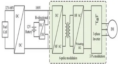
Fig. 1.Functional diagram of a fuel cell propulsion system.
time. It reduces the average switching frequency and limits the switching losses to 33% of the conventional value.Cascading does not affect the modulation implementation, or in other words the proposed SRSPM is applicable to single full-bridge unit too. Interleaving is shown to increases power transfer capacity [5].Fig.1. Functional diagram of a fuel cell drive system. Though a similar hybrid modulation technique for inverter control has been proposed earlier models, the front-end dc/dc converter essentially has minimum three full bridges employing standard three-phase SPWM with three references[9][10][13].. It results in complex control and has major issue of circulating current among the bridges conducted by semiconductor devices. If one bridge fails, the modulation fails, i.e., the However, the proposed modulation scheme works with single bridge too owing to single reference approach. Devices at symmetrical location in two bridges are operated by identical gating signals. The merit of this innovation is unique single reference that is developed to contain information of six-pulse waveform. Since, identical single reference is given to both the front-end bridges, in case of failure of one of the bridges; the other bridge still produces the same six-pulse pulsating waveform at the dc link and then the balanced three-phase inverter output voltage.
Therefore, single-reference modulation with interleaved or cascaded front-end offers higher reliability as compared to that proposed previously. This technique is used in the different applications like Fuel cell vehicles, Electrical vehicles, Uninterrupted power supply (UPS), PV Systems, Islanded microgrid, Solid state transformers. The circulating current between the bridges is eliminated. Conventional modulation [9], [10] suffers from circulating current between the bridges (i.e., through semiconductor devices) causing additional losses.This paper objective is to explain steady-state operation and analysis of the two stage HF inverter employing the proposed modulation scheme, reported in Section 2. The design of the converter has been illustrated in Section 3. The design and analysis have been verified by simulation results using MATLAB 7.12.0.635 in Section modulation scheme.Pulsating dc voltage does not contain six-pulse information anymore, and hence, the inverter is not able to produce balanced three-phase output. The proposed modulation has unique single
reference signal. Even if a bridge fails, the other will maintain six-pulse information in pulsating dc-link voltage and inverter is still able to produce balanced three-phase voltage. It is, therefore, robust and offers higher reliability.
The overall system has the following merits: 1) Elimination of dc-link electrolytic
capacitor: reduces volume of system and improves reliability
2) Reduced average switching frequency of inverter: at any instant of time, only one leg of inverter is modulated at HF keeping other two legs at same switching state. This reduces the switching losses and improves efficiency. Switching losses are further reduced because the devices are not commutated when current is at its peak.
3) Single reference front-end modulation: A single reference signal is used to implement sixpulse modulation to produce pulsating dc voltage at the dc link. The proposed inverter has better reliability compared to existing topologies owing to single-reference modulation.
II. RELATED WORK
Previously [9] and [10] having three full-bridges at front-end are used and standard three-phase SPWM is employed that uses three single phase sine references. Three single-phase HF transformers are connected to compute maximum line-to-line and generate pulsating dc voltage with six-pulse information. Modulations of three full-bridges are dependent mutually on each other to produce pulsating six-pulse waveform at the dc link of the inverter.
producing balanced three-phase sine output. Interleaving (two bridges at front-end) is done to increase the power transferring capacity [1].
III. OPERATION AND ANALYSYS OF THE CONVERTER
In this section explained the steady state operation and analysis of the modulation technique. Two full-bridge converters are cascaded or interleaved at front-end in parallel input series output to increase the power transfer capacity as shown in Fig.2. Both full-bridges are modulated using identical six-pulse modulation producing HF pulsating dc voltage Vdc, which is given to a standard three-phase inverter. Modulation of the two stages is planned, developed, and implemented, so as to reduce the switching losses of inverter while making dc link capacitorless. The three-phase inverter is modulated to shape this HF pulsating dc-link voltage to obtain balanced three-phase sine inverter output voltages of required frequency and amplitude after filtering.
The following assumptions are made for easy understanding of the analysis of the converter:
1) All semiconductor devices and components are deal and lossless.
2) Leakage inductances of the transformers have been neglected.
3) Dc/dc converter cells are switched at higher frequency compared to the inverter.
Therefore, current drawn by the inverter, idc remains approximately constant over one HF switching cycle of the dc/dc converter. Magnetizing inductances of the HF transformers are denoted as Lma and Lmb in Fig.2. one third of the line cycle. An important note is the devices do not commutate when current through them is at its maximum value
A) Modulation:
The switch pairsM1a−M2a and M3a− M4a are operated with complementary signals. Reference signal Vref is a six-pulse waveform that is obtained from the rectified output of three-phase line-line voltage as shown in Fig.2. As the name suggests, the reference voltage is having frequency of 6× ac line frequency. These six equal pulses are flagged as T1 to T6. During each of these pulses, only one leg of the inverter is modulated at HF whereas remaining two legs are steady at their switching state.
The modulating sequences of the inverter switches S1−S6 are given in Table 1, which are compared with carrier waveform to get gating pulses for the devices. During time interval T1, S4 and S5 are ON, and S3 and S6 are OFF. S1 and S2 are modulated at HF by using Vab/Vcb as modulating signal. It can be clearly observed from Fig.3 that only two (1 leg) of six devices (3 legs) are switched at HF resulting in reduction of number of switching instants in a line cycle. Similar procedure is followed for remaining five segments. In a complete line cycle, each semiconductor device is switched at HF only for This modulation technique is very easy to implement by using three-phase line–line voltages as This further reduces the switching losses lower than 33%. The modulation given in Table 1 produces a low harmonic distortion of the output waveforms as compared to previous method that gives an unsymmetrical wave shape. In the proposed method, exact modulating signals are calculated by considering variation in average dc-link voltage in six-pulse form references shown in Fig.3.
B) Steady State Operation:
The converter operation during different intervals of a HF switching cycle is highlighted by waveforms shown in Fig.4 Gating signals of dc/dc full-bridge converters are shown, where each switch is operated at 50% duty ratio and complementary to other switch in the same leg.
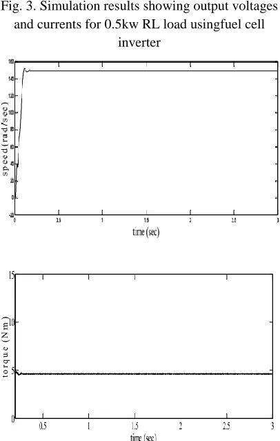
Fig. 3. Simulation results showing output voltages and currents for 0.5kw RL load usingfuel cell
inverter
Fig.4. Simulation results showing speed and torque 0.8kw induction motor load usingfuel cell inverter
Whenever the diagonal switch pairs are conducting, say M1a and M4a, input voltage Vin appears across
the transformer primary and nVin is reflected on the secondary side. On the other hand, when other diagonal pairM2a and M3a are conducting, −nVin is obtained across secondary terminals, where n is the turns ratio of the transformer. Another full-bridge unit is also operated in similar manner applying similar gating pulses to symmetrical devices. Bipolar pulsating voltage is converted to unipolar using full-bridge diode rectifier circuit. Rectifier outputs from two cells are connected in series to add the voltage level. The average value of the rectifier output voltage at dc link over a switching cycle is obtained as
VRa = VRb = 2D · n · Vin ……….(1)
Vdc = VRa+ VRb= 4D · n · Vin……….. (2)
Where D is the duty ratio of the converter.In the proposed modulation scheme, the duty ratio D is generated from Vref which is a six-pulse waveform. The duty ratio varies between its maximum Dmax and minimum values Dmin for required three-phase output voltages as the Vref varies at 300 Hz. The maximum value of voltage obtained at Vdc corresponds to the peak of line to line inverter output voltage is obtained at Dmax and is obtained as
VX Y,peak = 4Dmax · n ·
Vin………. (3)
Where VXY,peak is the peak of line-line output voltage. Magnitude of output voltage can be varied by varying the reference voltage Vref, which changes the range of operating duty ratio Dmin and Dmax.
C) Switching Losses:
around 7.5 times for the proposed modulation method as compared to the standard sine pulse width modulation (SPWM).
III. INVERTER DESIGNING
The design procedure is illustrated by a design example for the following specifications: Input voltage Vin = 100 V, output phase voltage VO = 110 V at fO = 50 Hz, rated power PO = 400 W, switching frequency of dc/dc converter fSC = 100 kHz, and of inverter fSI = 40 kHz.
1) Average input current is Iin = PO/(ηVin ). Assuming an efficiency η of nearly 95%, Iin = 4.21 A. Each full-bridge is sharing half of the load, Iina = Iinb = Iin /2 = 2.1 A.
2) Maximum value of average voltage at dc link should be above peak value of line–line output voltage Vdc =√3·√2 · Vo = 270 V
3) The turns ratio of the transformers are designed by considering the operating duty ratio of the full-bridge converter as 0.4– 0.425.
4) The turns ratio of 1.6 is selected allowing safe margin in case of decrease in input voltage below100V. Transformer primary needs to carry current of Iin /2 = 2.1 A. Rating of the full-bridge converter: Switches M1a−M4a and M1b−M4b are rated to conduct current of Iina = Iinb = 2.1 A and rated to withstand voltage of Vin = 100 V.
Fig.5. Waveforms showing gating signals of the
full-bridge converter.
IV. SIMULATION RESULTS
The given modulation scheme has been simulated using software package MATLAB 7.12.0.635 for the given specifications. Simulation results are illustrated in Figs. 7 to 8 matching closely with the theoretical predicted waveforms and results. The modulation for the inverter devices is derived by comparing modA, modB, and modC waveforms with the carrier signal of 40 kHz.
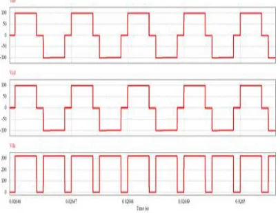
Fig.7. Simulation results showing references (Vab, Vbc, and V ca), output phase voltages (Vxn, Vyn, and Vzn) and output line current (Ix, Iy, and Iz) waveforms at rated load under the normal operating condition.
Fig. 8. Simulation output showing voltages VA B , VC D , and Vdc at rated load under the normal
operating condition.
The series connected rectifier output voltage is shown in Fig. 8 as explained in the analysis.
V. CONCLUSION
Fuel cells are becoming lucrative solution toward sustainable low carbon cleanmobility owing to zero emission .This paper proposes a novel modulation techniquenamed SRSPM to control front-end full-bridge converter to generate HF unipolarpulsating voltage waveform at dc link having six-pulse information if averaged at HFcycle over line frequency.. Six-pulse is meant for six-pulse waveform that results after rectification of three-phase balanced ac waveforms at 6×of line frequency. It permits the next three-phase inverter devices toswitch at HF during 33.33% (1/3 rd) of the line cycle and remains to stay at steady switching state of ON for 33.33% and OFF for rest 33.33% of line cycle. It results in low average switching frequency or 66.66% reduction inswitching transition losses and improved efficiency.Compared to three-phase inverter, reduction in switching loss up to 86.6% is accomplished. It is suitable for highpower applications like FCVs and EVs, three-phase uninterruptible power supply (UPS), islanded or standalone micro-grid, and solid-state transformer.
REFERENCES
[1]U.R.Prasanna and A.K.Rathore, “ A Novel Single reference six pulse modulationtechnique based interleaved high frequency three phase inverter”, IEEE Trans.Power Electron., vol. 28, pp. 5547–
5556,no. 12, dec.2013.
[2] S. J. Jang, C. Y. Won, B. K. Lee, and J. Hur, “Fuel cell generation system with a newactive clamping current-fed half-bridge converter,” IEEE Trans. Energy Convers.,vol. 22, no. 2, pp. 332–340, Jun. 2007.
[3] S. K. Mazumder and A. K. Rathore, “Performance evaluation of a new hybridmodulation scheme for high-frequency-ac-link inverter: Application for PV, wind,fuel-cell and DER/storage applications,” in Proc. IEEE Energy Convers. Congr. Expo., 2010, pp. 2529–2534.
[4] R. Huang and S. K. Mazumder, “A soft switching scheme for multiphasedc/pulsating-dc converter for three-phase high-frequency-link pulse widthmodulation (PWM) inverter,” IEEE Trans. Power Electron., vol. 25, no. 7, pp. 1761–1744, Jul. 2010.
[5] A. Khaligh and Z. Li, “Battery, ultra capacitor, fuel cell, and hybrid energy storagesystems for electric, hybrid electric, fuel cell, and plug-in hybrid electric vehicles:State of the art,” IEEE Trans. Veh. Technol., vol. 59, no. 6, pp. 2806–2814, Jul. 2010.
[6] A. Emadi, S. S.Williamson, and A. Khaligh, ―Power electronics intensive solutions for advanced electric, hybrid electric, and fuel cell vehicular power systems,” IEEE Trans. Power Electron., vol. 21, no. 3, pp. 567–577, May 2006.
[7] A. Emadi, K. Rajashekara, S. S. Williamson, and S. M. Lukic, ―Topological overview of hybrid electric and fuel cell vehicular power system architectures and configurations,” IEEE Trans. Veh. Technol., vol. 54, no. 3, pp. 763–770, May 2005. [8] A. Khaligh and Z. Li, ―Battery, ultra capacitor, fuel cell, and hybrid energy storage systems for electric, hybrid electric, fuel cell, and plug-in hybrid electric vehicles: State of the art,” IEEE Trans. Veh. Technol., vol. 59, no. 6, pp. 2806–2814, Jul. 2010.
[10] J. M. Miller, ―Power electronics in hybrid electric vehicle applications,” in Proc. 18th IEEE Appl. Power Electron. Conf., Miami Beach, FL, USA, Feb. 2003, vol. 1, pp. 23–29.
[11] J.-S. Kim, J.-M.Ko, B.-K. Lee, H.-B.Lee, T.- W. Lee, and J.-S. Shim, ―Optimal battery design of FCEV using a fuel cell dynamics model,” in Proc. Telecommun.EnergyConf., 2009, pp. 1–4.
[12] E. Schaltz, A. Khaligh, and P. O. Rasmussen, ―Influence of battery/ ultra capacitor energy-storage sizing on battery lifetime in a fuel cell hybrid electric vehicle,” IEEE Trans. Veh. Technol., vol. 58, no. 8, pp. 3882–3891, Oct. 2009.
[13] P. J. Wolfs, “A current-sourced dc-dc converter derived via duality principle form half bridge inverter,” IEEE Trans. Ind. Electron., vol. 40, no. 1, pp. 139–144, Feb. 1993.
[14] A. Averberg, K. R. Meyer, and A. Mertens, “Current-fed full-bridge converter for fuel cell
systems,” in Proc. IEEE Power Energy Society
General Meeting, 2008, pp. 866–872.
[15] S. J. Jang, C. Y. Won, B. K. Lee, and J. Hur, “Fuel cell generation system with a new active clamping current-fed half-bridge converter,” IEEE Trans. Energy Convers., vol. 22, no. 2, pp. 332–340, Jun. 2007.
BIODATA
Konam Ramesh completed M.tech (power system).