HOURANI, RAMSEY S. A Performance Analysis Framework for the Design of DSP Systems. (Under the direction of Professors Winser E. Alexander and W. Rhett Davis).
The competitive market for generating smaller and faster portable devices compels designers to meet stringent design requirements while keeping time-to-market as low as pos-sible. Application specific integrated circuits and field programmable devices are popular choices for implementing computationally intensive signal processing systems on hardware platforms due to their high speed and low power characteristics. However, the gap between the complex digital signal processing (DSP) algorithm and the efficient hardware implemen-tation continues to grow with the advances in technologies and stringent design constraints. This work presents a performance analysis framework as a method for bridging the gap between the DSP algorithm and the efficient hardware implementation.
The work presented in this dissertation focuses on refining a basic DSP algorithm, such as an FIR filter, to several hardware implementations that are closely matched in performance while meeting design constraints. The design methodology in this work uses CAD and EDA tools accepted by both industrial and academic venues. The framework refinement process invokes C++ scripts that efficiently generate and model the DSP algo-rithms and hardware designs at multiple levels of abstraction. Additionally, scripts within the framework invoke a Synopsys Design Compiler that accurately and efficiently estimates circuit-level performance metrics including area, throughput and power dissipation.
by
Ramsey S. Hourani
A dissertation submitted to the Graduate Faculty of North Carolina State University
in partial fulfillment of the requirements for the Degree of
Doctor of Philosophy
Electrical Engineering
Raleigh, North Carolina
2007
APPROVED BY:
Dr. William Edmonson Dr. Zhilin Li
Dr. Xun Liu
Dr. Winser E. Alexander Dr. W. Rhett Davis
Dedication
To my parents, Salim and Buran Hourani
my brother, Sammy
Biography
Acknowledgements
I would like to thank my advisor and mentor, Dr. Winser E. Alexander for his patience and perseverance, for his encouraging words, his invaluable knowledge, and price-less advice throughout my research. I would also like to thank Dr. W. Rhett Davis for taking the time to listen to my ideas and guide me in fine tuning my work. I also thank Dr. William Edmonson, Dr. Zhilin Li, and Dr. Xu Liu for their assistance throughout my dissertation research. I would also like to thank all my instructors who helped me in all aspects of my education.
I cannot neglect the brotherhood I developed among my fellow colleagues through the course of my research. I would like to thank Lalit Ponnala for reviewing my papers, Cranos Williams for his challenging games of racket ball, YoungSoo Kim for our countless discussions, Ishita Dalal for implementing a number of my ideas, Ravi Jenkal for his con-structive feedback regarding my work, and my close friend Senanu Ocloo for encouraging me through those days of despair. I would also like to thank Lisa McGee, Sandeep Hattangady, Maitrik Diwan, ChuanHua Xing, Julian Taylor, Treshauna Wright, Musaab Mohammedali and Gary Charles.
My life-long friends whom I have grown to respect more and more with every passing day always encouraged me to pursue this degree from the start. I would like to thank my close friend Clint Stanerson and his wife and children. I would also like to thank Mezyad Ammoura, Omar Masri, Mohammed Al-Najjar and their families. I also thank my dear friend Ayman Zohbi who has looked up to me and listened to my words of advice when he decided to pursue his PhD. All my friends have contributed in some part to the success of my work.
I would like to acknowledge and thank my parents Salim and Buran for their con-stant prayers for me. I would also like to thank my brother Sammy for his encouragements and my sister Eman (Mimi) for listening to me vent during my days of hardship. I would also like to thank my sister Leena, her husband Mathew, and her two sons Ramsey and Sammy for their kind words of encouragement. I also thank my sister May, her husband Samir and her precious son Ramsey for shining light into my days as a student. Last but not least, I thank all my extended family for wishing me luck throughout my studies.
Contents
List of Figures ix
List of Tables xi
List of Abbreviations xii
List of Symbols xiv
1 Introduction 1
1.1 Overview . . . 4
1.2 Motivation . . . 5
1.3 Contributions of This Work . . . 6
1.4 Organization . . . 8
2 Related Work: Refining DSP Algorithms to Hardware 10 2.1 Levels of Design Abstraction . . . 10
2.2 EDA Tools for Modeling Hardware Designs . . . 14
2.2.1 MATLAB . . . 16
2.2.2 SystemC . . . 16
2.2.3 Verilog Hardware Description Language . . . 19
2.2.4 Synopsys Design Compiler . . . 19
2.2.5 Synopsys DesignWare DSP IP Library . . . 20
2.3 Design Environments for DSP Hardware Blocks . . . 22
2.3.1 Synopsys Module Compiler . . . 23
2.3.2 HYPER . . . 24
2.3.3 FIR Compilers . . . 26
2.3.4 SystemC for Hardware Design and Verification . . . 26
2.3.5 AccelChip . . . 27
2.4 Commercial Tools for Hardware Synthesis . . . 30
2.4.1 AccelDSPTM Synthesis Tool by Xilinx . . . . 31
2.4.2 Catapult-C by Mentor Graphics . . . 31
2.5 Chapter Summary . . . 34
3 Performance Analysis Framework 36 3.1 Performance Analysis Framework Methodology and Flow . . . 37
3.1.1 EDA Tools used for the PAF . . . 38
3.1.2 Framework Methodology and Flow . . . 39
3.1.3 Hardware Design and Synthesis Process . . . 41
3.1.4 Design Space Reduction using Cost Functions . . . 44
3.2 Hardware Performance Metrics . . . 46
3.2.1 Area . . . 46
3.2.2 Critical Path Delay . . . 47
3.2.3 Hardware Latency . . . 48
3.2.4 Design Throughput . . . 49
3.2.5 Power Dissipation . . . 50
3.2.6 Computational Precision . . . 50
3.3 Design Cost Functions and Figures of Merit . . . 53
3.3.1 Power Density . . . 54
3.3.2 Power Efficiency . . . 54
3.3.3 Area Efficiency and Area-delay-product . . . 55
3.3.4 Additional Figures of Merit . . . 56
3.4 Design Options Applied at Different Levels Abstraction . . . 57
3.4.1 Algorithmic Level . . . 57
3.4.2 Architectural Level . . . 58
3.4.3 Arithmetic Level . . . 60
3.4.4 Circuit Level . . . 62
3.5 Chapter Summary . . . 64
4 Case Study I: Digital Finite Impulse Response Filters 66 4.1 Algorithmic Level . . . 67
4.2 Arithmetic Level . . . 69
4.2.1 Data-Type Representation . . . 69
4.2.2 Data Scaling . . . 70
4.2.3 Coefficient Scaling to Avoid Overflow . . . 71
4.3 Architectural Level . . . 76
4.3.1 FIR Filter Structures . . . 76
4.3.2 Second Order Sections . . . 78
4.3.3 Polyphase Structures for Multirate Signal Processing . . . 79
4.3.4 Symmetric FIR Filters . . . 80
4.3.5 Interleaving for Multi-Signal Processing . . . 82
4.3.6 Pipelining Types . . . 84
4.4 Circuit Level . . . 88
4.4.1 Circuit Architectures for Arithmetic Blocks . . . 88
4.4.2 Combined Pipelining and VDD scaling . . . 88
4.4.3 Performance Metrics and Cost Functions . . . 89
4.6 FIR Filter Applications and Design Examples . . . 92
4.6.1 High-Throughput Filters . . . 92
4.6.2 Area-Efficient and High-Throughput Filters . . . 96
4.6.3 Low-Power and High-Throughput Filters . . . 98
4.7 Chapter Summary . . . 101
5 Case Study II: Adaptive Channel Equalizers 103 5.1 Adaptive Equalizer using the LMS Algorithm . . . 104
5.2 Finite Word Length Effects . . . 108
5.3 Architectural Implementation . . . 109
5.4 Circuit-Level Performance Metrics . . . 112
5.5 Equalizer Applications and Design Space Analysis . . . 114
5.5.1 Area-Efficient Designs . . . 114
5.5.2 High-Throughput Designs . . . 117
5.5.3 Low-Power Designs . . . 119
5.6 Chapter Summary . . . 121
6 Case Study III: Discrete Wavelet Transforms 123 6.1 Discrete Wavelet Transform Algorithm . . . 124
6.2 Fixed-Point Algorithmic Analysis . . . 125
6.3 DWT Hardware Architectures . . . 126
6.3.1 Basic DWT Implementation . . . 126
6.3.2 Survey of DWT Architectures . . . 128
6.3.3 Efficient Filter Blocks Using the PAF . . . 129
6.4 DWT Design Space Analysis . . . 130
6.5 Performance Evaluation . . . 132
6.6 Chapter Summary . . . 134
7 Framework Evaluation 136 7.1 Synthesis Times Using Pre-Synthesized Blocks . . . 136
7.2 Estimating Performance Metrics Using Pre-Synthesized Blocks . . . 138
7.3 Validating PAF Architectures . . . 140
7.4 PAF versus Similar Frameworks . . . 144
7.4.1 Synopsys DesignWare IP Blocks . . . 144
7.4.2 High-Level Synthesis . . . 145
7.4.3 AccelDSP and FIR Compilers . . . 147
7.5 Chapter Summary . . . 147
8 Conclusions and Future Work 150 8.1 Conclusions . . . 150
8.2 Future Work . . . 153
8.2.1 Mapping DSP Algorithms onto FPGAs . . . 154
8.2.2 Additional DSP Functions and Algorithms . . . 155
8.2.3 Educational Venues . . . 159
List of Figures
1.1 Hardware refinement process: from algorithm to netlist. . . 3
1.2 Flexibility vs. efficiency . . . 5
2.1 System modeling graph . . . 11
2.2 Levels of design abstraction: from algorithm to hardware layout. . . 15
2.3 Synopsys DesignWare High-Speed Digital FIR Filter. . . 21
2.4 Synopsys DesignWare Area-Efficient Digital FIR Filter. . . 22
2.5 Cascade versus parallel structure for FIR filter example. . . 25
2.6 Simulation times for different levels of SystemC abstraction . . . 28
2.7 AccelChip Design Flow . . . 29
2.8 Catapult-C Synthesis Design Flow . . . 32
2.9 Sequential loop versus unrolled code for MAC algorithm . . . 33
3.1 Concept of the Performance Analysis Framework . . . 37
3.2 Performance Analysis Framework Flow . . . 40
3.3 Bottom-up modular design . . . 42
3.4 Architectural variations using computational cells . . . 43
3.5 Area versus word size for mathematical cores . . . 48
3.6 Pipelining to improve critical path and hardware utilization . . . 49
3.7 Binary representation for generalized fixed-point numbers . . . 52
3.8 Overflow Modes . . . 53
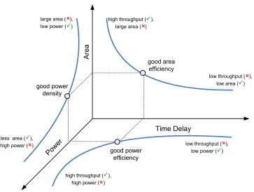
3.9 Trade-off curves for hardware designs . . . 54
3.10 Power-Delay trade-off curve . . . 56
3.11 Input/output word sizes for DSP hardware designs . . . 62
3.12 Quantization and rounding errors for DSP hardware models . . . 63
4.1 Lowpass FIR filter frequency response . . . 68
4.2 Input and output plots for an 12th order FIR filter . . . 75
4.3 SFG for DF and TF FIR filters . . . 77
4.4 SFG for additional FIR filters . . . 78
4.5 SFG for down-sampling filters . . . 80
4.7 Linear-phase FIR filter structures . . . 83
4.8 Pipelining hardware designs using cut-set retiming . . . 86
4.9 Pipelined computational modules . . . 87
4.10 Executing the PAF flow for analyzing FIR filters . . . 90
4.11 High-throughput filter options . . . 94
4.12 Pareto-optimal power-delay curves . . . 95
4.13 Comparison of high-throughput filter structures . . . 96
4.14 Comparison of area-efficient filter structures . . . 98
4.15 Low power, high throughput filter options . . . 100
5.1 Channel impulse response and eye diagram for corrupted signal . . . 105
5.2 Adaptive equalizer Filter taps vs SNR . . . 106
5.3 Convergence rate for non-pipelined filter structures . . . 108
5.4 Finite word length effects of adaptive equalizer algorithm . . . 109
5.5 SFG for adaptive equalizer hardware design . . . 110
5.6 Framework flow for analyzing adaptive equalizer designs . . . 112
5.7 Hardware structures for error estimator and coefficient update blocks . . . . 113
5.8 Design permutations for adaptive equalizer computational blocks . . . 113
5.9 Area-efficient equalizer design . . . 115
5.10 Design space for area-efficient equalizer designs . . . 116
5.11 Area-efficient equalizer design generated by PAF . . . 117
5.12 Low-power equalizer design . . . 120
5.13 Low-power equalizer design generated by PAF . . . 122
6.1 Three-stage, eight-channel subband decomposition . . . 127
6.2 PAF design options for efficient DWT filter blocks . . . 130
6.3 Efficient implementation for 1D DWT architecture . . . 132
6.4 Performance metrics for DWT design space . . . 133
6.5 Pipelined TFII FIR filter used in DWT design . . . 134
7.1 Synthesis methods employed by the PAF . . . 138
7.2 Comparison of accuracy in metric estimation . . . 141
7.3 Automated architectural verification process . . . 143
7.4 Xilinx LogicCORE T M FIR Compiler Symmetric FIR filter . . . 148
8.1 Summary of goals and contributions for the PAF flow . . . 151
8.2 Various hardware implementations for matrix-vector multiplication . . . 157
8.3 Modular design methodology applied to IIR filter . . . 158
List of Tables
2.1 Synopsys DesignWare IP DSP components . . . 20
3.1 Area for DesignWare mathematical cores . . . 47
4.1 Methods for scaling filter input and coefficients . . . 74
4.2 Effects of quantization on fixed-point FIR filter . . . 75
4.3 Performance metrics for 8th order SOS FIR filter . . . 79
4.4 FIR filter structures used for adaptive equalizer design . . . 91
4.5 High-throughput filter specification . . . 93
4.6 Performance results for high-throughput filters . . . 95
4.7 Area and throughput-efficient filter specifications . . . 97
4.8 Performance results for area and throughput-efficient filters . . . 98
4.9 Low-power, high-throughput filter specifications . . . 99
4.10 Performance results for low-power, high-throughput filters . . . 101
5.1 Area-efficient equalizer specifications . . . 116
5.2 Performance results for area-efficient equalizers . . . 117
5.3 High-throughput equalizer specifications . . . 118
5.4 Performance results for throughput-efficient equalizer . . . 119
5.5 Low-power equalizer specifications . . . 120
5.6 Performance results for low-power equalizers . . . 121
6.1 Quantization results for fixed point DWT implementation . . . 126
6.2 Performance results for 1D DWT Design Space . . . 131
6.3 Performance comparison for 16-tap, 3-level DWT Designs . . . 135
7.1 Synthesis times for different order FIR filters . . . 139
7.2 Comparison between Synopsys TF filter and PAF TF filter . . . 145
7.3 Behavioral FIR filter design versus framework filters . . . 146
7.4 Comparing Xilinx FIR Compiler to PAF FIR symmetric filters . . . 148
List of Abbreviations
ASIC Application Specific Integrated Circuit
BER Bit Error Rate
CDF Control Data Flowgraph
CLB Configurable Logic Block DCT Discrete Cosine Transform
DF Direct Form
DFF D-type Flip Flop
DSP Digital Signal Processing DWT Discrete Wavelet Transform EDA Electronic Design Automation FDA Filter Design and Analysis
FIR Finite Impulse Response
FFT Fast Fourier Transform
FPGA Field Programmable Gate Array
FSM Finite State Machine
GDS Graphic Data Systems
GUI Graphical User Interface
HLS High Level Synthesis
IC Integrated Circuit
IIR Infinite Impulse Response
IP Intellectual Property
ISI Inter-Symbol Interference
LMS Least Mean Square
MAC Multiply/Accumulate
MSB Most Significant Bit
MSE Mean Square Error
OSCI Open SystemC Initiative
PAF Performance Analysis Framework
PE Processing Element
QMF Quadrature Mirror Filter RTL Register Transfer Level
SFG Signal Flow Graph
SIR Signal-to-Interference Ratio SNR Signal-to-Noise Ratio
SoC System-on-Chip
SOS Second Order Section
TF Transpose Form
List of Symbols
α Switching Activity Factor
λ Technology Feature Size
A Silicon Area
AT Area Efficiency (Area-Delay Product)
AT2 Area-Delay Squared Product
C1 Filter Input Scale Factor
C2 Filter Coefficient Scale Factor
C3 Filter Output Scale Factor
Cswitch Switching Capacitance
D Filter Down-sample Rate
fop Design Operating Frequency
f Fixed-point fractional size
J Linear-phase FIR Filter Length
K Filter Signal Length
L Hardware Latency
M FIR filter order
N IIR filter order
Pdynamic Dynamic Power Dissipation
P/A Power Density
P T Power Efficiency (Energy)
P T2 Energy-Delay Product
R Design Throughput
T Unit-Sample Response
Td Design Delay
Td,max Critical Path Delay
U Filter Up-sample Rate
Vth Threshold Voltage
VDD Supply Voltage
ω Angular Frequency (rad/s)
w Fixed-point word size
Chapter 1
Introduction
Silicon process technology has greatly advanced since the discovery of the transistor in 1948 by John Bardeen and Walter Brattain at the Bell Telephone Laboratories [1]. In 1965, Gordon Moore predicted that the number of transistors per integrated circuit (IC) would continue to double every eighteen months or so [2]. Until recently, a system required multiple IC’s on a single board, each IC performing a certain application. Technology feature sizes have continued to decrease to the stage where what was once designed using several IC’s can now be designed on a single IC consisting of billions of transistors. The design of a system on a single chip is referred to as a System-on-Chip (SoC). The efforts of designing such complex digital circuits has also increased over the years, which paved the way for developing computer-aided design (CAD) and electronic design automation (EDA) tools and methodologies. These methodologies provide system designers the means for continuously refining abstract design specifications to realizable hardware and software blocks. The methodologies continue to increase in complexity as the functionality of the systems grow. Modifying the design methodologies and design tools may become impractical or inefficient to meet the implementation gap. Therefore, designers are forced to develop new and improved CAD tools to cater to complex designs.
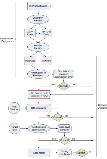
the system at multiple levels of design abstraction using extensions of C++, which is an important strategy for the successful design of a system [3]. System designs can be refined through different levels of abstraction. The design details become more visible as the design progresses from a higher level of abstraction to a lower level. This allows the system designers to either refine the design to meet the system specifications or to modify the specifications to meet realizable design performance constraints at any level of abstraction. Digital signal processing (DSP) algorithms are examples of computationally in-tensive systems that can perform better when mapped onto a hardware platform. A com-putationally intensive algorithm requires several iterative stages of coding, designing and simulation in order to refine it to a synthesizable hardware block as Figure 1.1 illustrates [4]. MATLAB,C/C++ or a combination of the two are commonly used as a high-level language
to describe a DSP algorithm. Designers use performance criteria set by the system spec-ifications to determine the partitioning of a DSP algorithm into software and hardware components. Parts of the algorithm that are refined to hardware components undergo rigorous design and analysis procedures in order to ensure that the hardware performance metrics meet the system specifications. Designers model the hardware algorithm at different levels of abstraction until the design is described at the synthesizable register transfer level (RTL). One of the bottlenecks in the hardware refinement process is manually designing the DSP hardware model while maintaining a high level of performance. Hardware designers manually and iteratively add design details to the point that commercial Synthesis tools, such as Synopsys Design Compiler [5], can further refine the design to a level suitable for IC fabrication. Refining all or parts of an algorithm to an efficient hardware implementation requires the efforts of several groups of designers. Each group tends to be proficient at describing the design at a particular level of abstraction. Designers that adopt the refine-ment process of Figure 1.1 are faced with the challenge of designing an efficient hardware implementation in a reasonable time frame. The expertise gap between the different groups of designers hinders the task of designing an efficient hardware architecture that meets both time-to-market constraints and system performance specifications.
synthe-!
"# # $
! %! &! '
%
# % ( % !
) %% * !
+ , -% !
+ %
% !
. .
)% ,
-% %
.
% %
/
0 % 1
/
/
/ 0 %
0 %
1
1
1
sizable hardware design. However, most of these tools overlook the importance of assessing the quality of the hardware design to determine it’s efficiency in performance. Designer either have to contend with the hardware designs generated by these tools, or take it upon themselves to seek that golden hardware design that stands out among the rest in the design space.
1.1
Overview
DSP algorithms can be refined to run on general purpose processors, digital sig-nal processors, field programmable gate arrays (FPGA), or application specific integrated circuits (ASIC). The choice of platform depends on cost and performance constraints set by the complexity of the algorithms and by the system designers who refine the algorithms. Figure 1.2 illustrates an overview for comparing the cost and performance for different plat-forms [6], where cost refers to the time and effort required to develop the final product and performance refers to throughput, area, and power dissipation of the design. An example of some performance numbers that support the trend in Figure 1.2 can be obtained from [7].
General purpose processors are highly flexible, allowing designers to conveniently implement all or parts of a system in a relatively short time frame. However, the efficiency at which these processors can implement the algorithms is generally low, accounting for low throughput and high energy dissipation. A DSP algorithm can be refined such that it is mapped onto on FPGA or fabricated into an ASIC. For such platforms, the hardware implementation generally exhibits higher performance than the general purpose processors, but at a cost of limited flexibility. Additionally, mapping a DSP algorithm to an application specific hardware block requires the efforts of several designers, which increases design cost and prolongs design times. Therefore, designers would like to achieve a compromise between design flexibility, refinement effort and hardware performance.
One approach to improve the efficiency and performance of DSP hardware blocks is to employ a design methodology that combines several programming languages and EDA tools capable of efficiently generating hardware blocks and assessing the performance. The main advantage of this approach is to minimize the gap between the high and low levels of abstraction. MATLAB and C/C++ seem to be the programming languages of choice
! "
" "
" " #" " # " "
! " " " # #
Figure 1.2: Flexibility vs. efficiency ,source [7]
an extension to C++ can be established to allow the system designers to use it at
mul-tiple levels of abstraction. SystemC has been developed and is supported by an industry consortium known as the Open SystemC Initiative (OSCI) [3]. It consists of a number of major EDA companies making SystemC attractive for system designers to progressively refine algorithms and systems to lower levels of design detail within a single environment.
1.2
Motivation
to support approaches for designing at the system-level [8]. Two important levels of this approach are system-level synthesis and Intellectual Property (IP) reuse. The cost and ef-fort for generating such tools and IPs are so great that they are not available to the general user. As a result, designers continue to create more tools that are specialized for a small user base. The resulting confusion in using these tools increases the design complexity and degrades the quality of the hardware implementations.
DSP algorithm developers, as well as hardware designers, concentrate their efforts on establishing methodologies that efficiently refine a DSP algorithm to a synthesizable hardware design. Architectural diversities expand the design space for a signal processing algorithm to tens of realizable hardware designs. Varying technology size and supply volt-ages further extends the design space to hundreds of possible design permutations, each with a unique set of area, throughput and power metrics. This leads to performance trade-offs in the design space with no accepted way of quantifying performance efficiency using a single cost function that combines area, throughput and power. Designers are therefore forced to exhaustively search the design space looking for hardware designs that perform well and meet final design specifications, a process which also prolongs design time and degrades productivity.
The goal is therefore to develop a framework that efficiently generates hardware designs for DSP applications while simultaneously minimizing area, delay and power for a given set of design constraints. An important consideration in the development of such a framework is to include both DSP algorithm developers and hardware designers as the primary users. This is accomplished through the use of EDA design tools and programming languages commonly utilized by both groups of designers. Selecting the appropriate tools is important in reducing the design gap between the different groups of designers.
1.3
Contributions of This Work
This work was developed into a design and performance analysis framework (PAF) that facilitated the refinement process of an algorithm to a set of synthesizable hardware blocks. The resulting framework can be used to guide the designer through selecting a hardware im-plementation that performs well for a specific application. The hardware designs generated by the framework are suitable for mapping DSP algorithms onto ASICs and FPGAs.
lim-ited hardware experience can use the framework to analyze low-level hardware optimizations earlier in the design process. This allows them to provide the hardware designers sufficient details for the appropriate low-level optimizations. Alternatively, hardware designers can use this framework for generating IP cores that are optimized for specific DSP applications while maintaining correct input/output behavior of the DSP algorithm.
This work was initially developed for designing and analyzing the performance of hardware structures for FIR filters. We then considered DSP applications that required FIR filters as a major component of the overall system such as adaptive equalizers and quadrature mirror filter (QMF) banks. The framework currently generates performance reports for metrics such as design area, critical-path timing, throughput, hardware latency, computational precision, and power dissipation. Additionally, the framework provides the user cost functions that evaluate and assess the performance of the hardware structures within the design space. The performance metrics and cost functions can be used to assist the designer in making architectural selections for hardware blocks when designing larger DSP systems.
1.4
Organization
Chapter 2 presents an overview for a subset of design flows, CAD tools, EDA tools, and frameworks used to support designers in constructing hardware architectures for DSP algorithms. It categorizes the different flows and tools, highlighting the merits of each and how our framework addresses some of their deficiencies.
Chapter 3 introduces our design and performance analysis framework, along with the design methodology we developed for generating synthesizable DSP hardware IP blocks. The performance metrics and cost functions we use as part of our framework are discussed in greater detail. The chapter also describes the process we adopted for efficiently estimat-ing the performance metrics and generatestimat-ing the pertinent cost functions for the hardware designs.
performance metrics and cost functions to guide a system designer in selecting a hardware implementation that performs well in the design space for specific performance constraints. Chapters 5 and 6 illustrate how we use our framework to generate and analyze hardware designs for other, more complex, DSP algorithms that require FIR filters as a major component of the design. Chapter 5 uses the case study of adaptive channel equalizers whereas Chapter 6 uses the case study of discrete wavelet transforms. Both chapters highlight the appropriate types of optimizations, such as pipelining, parallelism, and/or voltage scaling, that improve the performance of the hardware designs in terms of area, throughput and power dissipation.
Chapter 7 evaluates the effectiveness of utilizing our performance analysis frame-work. The chapter illustrates the pertinence of the performance metrics and the usefulness of the cost functions for analyzing the hardware design space. The chapter also analyzes the accuracy and efficiency for refining a DSP algorithm to a hardware block that performs well.
Chapter 2
Related Work: Refining DSP
Algorithms to Hardware
This chapter presents an overview of relevant work in refining high-level algorithms to low-level hardware implementations. The chapter begins by mentioning the important levels of design abstraction suitable for refining a computationally intensive DSP algorithm to a synthesizable RTL model. Next, the chapter discusses the importance of each level of abstraction and highlights the appropriate EDA tools for designing at that level. We present a survey of tools described in the literature for algorithmic refinement, and mention several commercial-based high-level synthesis tools that are used to generate hardware designs from high-level code descriptions.
2.1
Levels of Design Abstraction
The process of refining a DSP algorithm to a synthesizable hardware model is iterative, wherein the system level designer initially models the algorithm using a high-level language such asC++or MATLAB [12]. The algorithmic model forms the basis for verifying
overall signal processing application. These constraints ensure that the hardware designs are feasible in terms of IC cost, throughput performance, and power dissipation, especially since advances in technology are paving the way for smaller, more complex portable devices. Distinguishing between the data communication and the computational elements of a system facilities the process for refining a high-level algorithm to hardware. The complexity of the algorithms and their applications means that different designers require different methods for separating the details of a design. Cai et al. [13] separated the de-sign space into communication and computation axes, while establishing different levels of design abstraction. They defined six levels of design detail, four of which were classified as transaction level models (TLM). In the TLM, the details of computation are hidden from the details of communication. Figure 2.1 shows the system modeling graph and the transitions between the different levels of communication and computation defined by Cai.
Figure 2.1: System modeling graph,source [13]
design with limited communication and architecture detail. MATLAB andC/C++ are ap-propriate programming languages for efficiently modeling the behavioral functionality of a DSP design. Thebus-functional levelmodels cycle accurate communication of data, but approximates the execution time of the computational elements. SystemC is one example of a programming language that accurately models designs at that level of abstraction. The cycle-accurate levelincludes adequate details of the processing element in order to accu-rately estimate both execution times and communication cycles. The details at this level of design include pin accuracies between the computational elements, as well as bit accuracies for internal and external data communication. HDLs are appropriate design languages for detailing the components of this level of abstraction. The implementation levelmodels the computational elements at the RTL which are used as inputs to synthesis tools. The synthesized designs are used to estimate area, throughput and power measurements which are essential for assessing the quality of the refined design.
Baganneet al. [14] defined four levels of abstraction within the realm of SystemC which is an extension to theC++ class libraries [3]. The four levels of abstraction, initially described by Grotker et al. in [15], are:
1. Untimed Functional Level: Algorithms are modeled using high-level languages with as little code as necessary. The behavior of the algorithm is simulated in order to determine algorithmic optimizations. This level of abstraction is necessary for establishing reference models that are used to verify the functionality of low-level designs. Similar to Cai’s specification model, languages such as MATLAB andC/C++
can be used for modeling designs at this level of abstraction.
2. Timed Functional Level: Some of the functional models are designed with inherent processing or communication delays to analyze the latency effects on the behavior of the system. This analysis governs the allowable latencies and throughput when considering the final hardware implementation. SystemC originated with this level of abstraction in mind, and therefore is appropriately used for the timed functional level.
and more accurate clock latencies. This level of abstraction addresses the communi-cation of the system components, and therefore, C++-based design languages could be used for this level of abstraction.
4. Cycle Accurate Level: This is the lowest level of the design process before synthesis. It describes the modules of the system by means of a data transfer from sequential circuits through combinational logic. This level of abstraction is equivalent to the RTL. Any of the widely accepted HDLs, such as Verilog or VHDL, can be used for modeling designs at this level. However, SystemC has the capability of describing a system using a synthesizable subset of the SystemC language which include data-types that are used for RTL synthesis [16]. This eliminates the requirement for manually translating the high levels of the design fromC++to a HDL language, saving on time
and reducing interpretation errors.
Alternatively to Caiet al. and Baganne’s et al. definitions for the different levels of abstraction, Gemmeke et al. [17] also divided the design space but catered the design details more towards DSP algorithms. The algorithmic level can be as simple as a few lines of code that equate the output to a function of the input. The signal processing algo-rithm is initially implemented using floating-point computations for algoalgo-rithmic verification. MATLAB and C++ are attractive choices of tools for efficiently modeling signal
hardware performance of the algorithm is effected by the type of arithmetic blocks used. One of the lowest levels of abstraction is the circuit level which determines the depth of the combinational logic between sequential circuits. Designers utilize synthesis CAD tools, such as Synopsys Design Compiler [5], for generating the final chip layout from the HDL design which is described in Graphic Data System (GDS) format. The GDS or GDSII is a database format and is the standard format for fabricating an IC.
Figure 2.2 summarizes the levels of abstraction presented by Cai [13], Baganne [14] and Gemmeke [17] which we consider in our work for refining a DSP algorithm to hard-ware. The refinement process is generally iterative with design considerations made after each level of refinement. The separation between the algorithm developer and the hardware architect occurs when transitioning from the functional levels to the cycle accurate levels. This is similar to the hardware refinement process illustrated in Figure 1.1 of Chapter 1. The bottleneck in design productivity occurs at that critical transition where hardware de-signers typically explore multitudes of hardware implementations, seeking the most efficient structure in the design space.
2.2
EDA Tools for Modeling Hardware Designs
! "
# $ " % &
'
( $ '
)
* "
% ( $ "
( $
&
+ ! ' , , - --+ (
)
. (
!
! /
!
!
+( ! !
! +(
!
+( !
! -
!
+ !
2.2.1 MATLAB
The majority of DSP algorithm developers use MATLAB [12] as the initial stages for their system designs. MATLAB has gained popularity over the past several decades for modeling image and signal processing applications. MATLAB is an appropriate choice of tools for bridging the gap between the signal processing developers and hardware designers. The technological advances in digital systems permit complex signal processing algorithms to be implemented in hardware. As recent as a few years ago, MATLAB made it’s way in the design flow for algorithm refinement and hardware modeling of ASIC and FPGA based designs [21].
2.2.2 SystemC
SystemC is a C++ class library and a methodology that allows system designers to effectively create a cycle-accurate model for software algorithms, hardware designs, and interfaces for SoC and system-level designs. The designer utilizes SystemC to create a system-level model for the design and perform simulations in a relatively short time frame to validate and optimize the designs. Additionally, SystemC allows the designers to ex-plore various algorithms and provide the hardware and software designers an executable specification of the system. The SystemC class library provides the necessary constructs to model system architectures which include hardware timing, concurrency and reactive behavior that may not be found in standard C++. The C++ object-oriented
program-ming language provides the ability to extend the language through classes, without adding additional syntactic constructs.
SystemC Highlights
the RTL [3].
1. Modules:
Modules are the basic blocks for partitioning a design. They allow designers to break complex systems into smaller, more manageable components, and to hide internal data representations and algorithms from other modules. In SystemC, a module is a hierarchical entity that can have other modules or processes contained in it. Modules contain ports, constructors, data members, function members, and channels.
2. Processes:
Processes are used to describe the functionality and behavior of a module and are therefore contained inside modules. Processes are functions that contain a sensitivity list identified to the SystemC kernel. A process is executed when at least one of the signals in the sensitivity list changes it’s value or state. There are three types of processes: METHOD, THREAD, and CLOCKED THREAD process. We primarily focus on
METHODprocesses for the level of design abstraction we adopt in our SystemC hardware designs. TheMETHODprocess is equivalent to an alwaysblock in Verilog RTL code.
3. METHOD Processes:
AMETHODprocess is the simplest form of SystemC’s processes. Their execution is trig-gered by a signal event contained within the method’s sensitivity list. The method is invoked when a signal in the method’s sensitivity list changes state, i.e. an event occurs. Once the method is invoked, it continues running until a “return” is encoun-tered or the end of the method function is reached, after which control is then passed back to the simulation kernel.
4. Constructors:
5. Ports:
Ports provide modules with a means for communicating with their surroundings by transferring data from processes within a module to processes within other modules. There are three types of ports defined in SystemC:input,output, andbidirectional. Ports are created from pre-defined SystemC template classes. A type passed as a tem-plate argument defines the type of data exchanged within the ports. This particular feature provides an advantage of using SystemC as a HDL over other HDLs such as Verilog or VHDL. Designers have the option of abstracting bit-true accuracy from hardware designs by utilizing other C++ data-types or even user-defined data-types. 6. Signals:
SystemC signals are similar to ports. They are used to provide data paths for con-necting processes within a module. Signals are also used to connect modules at the top level of a design to modules at lower levels of the design hierarchy. Signals differ from ports in that they do not have a mode attribute and therefore cannot determine data flow through them. Direction of data flow is determined by the port to which they are connected.
7. Rich set of data-types:
With the multiple levels of abstraction come SystemC’s fixed precision data-types which allow for fast simulation, especially at the higher levels of abstraction. The arbitrary precision types can be used for computations with large numbers, and the fixed-point data-types can be used for bit-true DSP applications. Ports and signals may be defined using standardC++ data-types, SystemC data-types, or user-defined types. This specific SystemC highlight is critical in improving the architectural design and exploration process we discuss in Chapter 3.
8. Cycle-based simulation:
versus VHDL for different levels of abstraction [22].
2.2.3 Verilog Hardware Description Language
Verilog is a HDL with specific syntax and semantics used to accurately model designs at the RTL. It was first standardized in December of 1995 by the Standards Group for Verilog; IEEE 1364-1995 [23]. The design language is commonly used as the back-end for EDA tools that generate synthesizable hardware designs from high-level description languages, as well as the front-end for commercially used synthesis tools such as Synopsys Design Compiler. Designs described at the RTL using Verilog are typically implemented using integer data-types, which provides bit-true accuracy for the hardware implementation. The performance of a hardware design is governed by the style in which the Verilog code is written. “Behavioral Verilog” is a style of coding that uses Verilog constructs and syntax to model the behavior of a design with fewer detail than at the RTL [24]. The coding style is closer to using a high-level programming language such as C. The results of synthesizing Behavioral Verilog depends on the complexity of the design and the coding style, and in some cases, may not be synthesized. However, it is difficult to predict or even determine how the synthesis tools refine the behavioral code to a gate netlist.
2.2.4 Synopsys Design Compiler
We utilized Synopsys Design Compiler in conjunction with scripting techniques to specify design constraints and extract area, delay, and power measurements post synthesis. Our synthesis methodology, described in Chapter 3 was modeled using parts of the “Chip in a day flow” that automated the process for synthesizing hardware designs [25] [26]. We used Synopsys Design Compiler to determine the fastest allowable clock frequency by measuring the largest critical path delay in the design. We estimated the design area based on the standard cell blocks used to build the hardware model, and power was determined by simulating the synthesized hardware design and measuring the switching activity of the circuit netlist. Synthesis times depended primarily on the size and complexity of the hardware design. As a benchmark, a 32-tap, 16-bit direct form FIR filter synthesized for minimum delay required approximately 30 minutes using an Intel Pentium-4, 3 GHz CPU Linux machine. This design consists of 32 16×16-bit multipliers, 31 32-bit adders and 31 16-bit registers. We elaborate on the significance of synthesis times in Chapter 7.
2.2.5 Synopsys DesignWare DSP IP Library
Signal processing algorithms are refined to synthesizable hardware before they are mapped onto an ASIC. Synthesis tool makers, such as Synopsys, provide parameterized IP cores for basic DSP applications, examples of which include FIR and Infinite Impulse Response (IIR) filters [27]. Table 2.1 lists the DSP components in the DesignWare Building Block IP. The DesignWare DSP components primarily include FIR and IIR filters which are the basic building blocks for many signal and image processing applications.
Table 2.1: Synopsys DesignWare IP DSP components
DSP Components Description
DW fir High-Speed Digital FIR Filter
DW fir seq Sequential Digital FIR Filter Processor
DW iir dc High-Speed Digital IIR Filter with Dynamic Coefficients
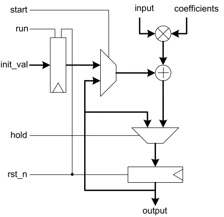
Parametrized IP cores reduces the overall design time. However, the Synopsys DSP IP cores lack additional optimization parameters that improve the performance of the design for certain applications. For example, the Synopsys DesignWare digital FIR filter components can be used for high-speed (DW fir) applications or area-efficient (DW fir seq) applications. The high-speed DesignWare FIR filter is implemented using a basic TF struc-ture shown in Figure 2.3 [28]. This strucstruc-ture uses N multipliers and N −1 adders in parallel to compute each output, where N is the number of filter taps. The data flow for this structure is one of the simplest forms to implement an FIR filter and requires minimal control logic. The coefficients are applied to the filter serially to reduce the input/output interconnects. This technique is useful for large order filters but may contribute to the overall initiation latency of the design. Alternative structures include a parallel input bus to supply the filter with the coefficients simultaneously.
The area-efficient DesignWare FIR filter is implemented using a single multiplier and adder shown in Figure 2.4 [28] and therefore requires additional control logic for correct signal synchronization and data transfer between the processing elements. This structure uses a multiply-accumulate (MAC) loop to perform the convolutional sum where each out-put sample is generated everyN clock cycles. Therefore, the throughput for this design is
N-times slower than the former DesignWare FIR filter.
Figure 2.3: Synopsys DesignWare High-Speed Digital FIR Filter.
De-Figure 2.4: Synopsys DesignWare Area-Efficient Digital FIR Filter.
signWare FIR filters to include additional optimizations such as pipelining, parallelism and interleaving. This would require the hardware designer to manually construct the basic fil-ter structure, and then proceed to ifil-teratively modify the structure to implement additional optimizations. Our work focused on expanding the basic filter structures to include archi-tectural optimizations that improve hardware performance based on the signal processing application. A detailed description of design optimizations is discussed in Chapter 4 where we explore the design space for different FIR filter structures.
2.3
Design Environments for DSP Hardware Blocks
applications include signal-to-noise ratio, signal-to-interference ratio, bit and symbol error rates, and probability of error [29] [30]. Establishing the algorithm parameters as early as possible is detrimental for efficiently designing the hardware components.
The system design process begins once the functionality of the signal processing algorithm is established. During this step, system designers discuss detailed specifications necessary to meet the functionality, performance, cost, and development time for the sys-tem. This step involves both the customers and designers in order to accurately reflect the customers requirements in a way that can be clearly followed by the designers during the refinement process. Examples of issues presented during the system specification are the integrity of the signals, size, weight, speed, power consumption and cost for the final overall system. All designers involved in the system development are constrained by time-to-market deadlines to ensure that the final product(s) hits the market at just the right time.
A large gap tends to exist between the signal processing algorithm and the efficient hardware implementation. Hardware designers seek EDA tools and design methodologies that attempt to bridge the gap between the algorithm and the hardware model. However, generating an efficient tool or methodology that spans the entire signal processing design space at its multiple levels of abstraction is almost unrealizable. Therefore, designers are compelled to create in-house tools and methodologies that cater to specific types of signal processing applications. Of the slew of tools and products available to DSP algorithm developers and hardware designers, only a handful have gained popularity in both academic and industrial venues. The following subsections provide an overview of EDA tools and methodologies catered towards refining signal processing algorithms to realizable hardware implementations.
2.3.1 Synopsys Module Compiler
the hardware performance subject to different mathematical operators. The synthesis tools returns the optimized mathematical implementations for a particular design.
The designer provides Module Compiler the hardware model for the DSP algo-rithm which requires a skilled hardware designer. Any variations at the architectural level may result in contradicting performance results. This requires the designer to use Mod-ule Compiler once more to optimize the mathematical operators for the modified hardware model. Module Compiler is an example of an EDA tool geared towards increasing produc-tivity by efficiently searching the design space for optimized designs, which is one of the highlights of our work. However, the user is burdened with having to manually model the various algorithms at the RTL in an attempt to obtain a design that has been optimized at both the architectural and circuit levels.
2.3.2 HYPER
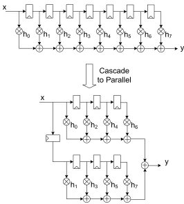
HYPER is an automated high-level synthesis system that applies architectural optimizations to minimize power dissipation while maintaining acceptable throughput and area measurements [32]. The approach is to explore the design space using flowgraph transformations that alter the performance of a design while preserving the input/output behavior. The tool is primarily utilized for exploring the effects of power dissipation subject to the architectural transformations. Power optimization is achieved using several hardware and signal processing techniques. This includes critical path reduction by transforming a single cascaded structure to a parallel structure, an example of which is illustrated in Figure 2.5 for the case of an FIR filter.
Figure 2.5: Cascade versus parallel structure for FIR filter example.
adder, then the critical path delay for the parallel structure is reduced by approximately
1
5 the original critical path delay. Therefore, to maintain the same throughput, the clock
frequency can only be reduced by 20%, which means that the supply voltage cannot be reduced by much.
2.3.3 FIR Compilers
Hawley et al. presented an FIR compiler for generating different hardware de-signs for FIR filters targeting ASICs [35]. Their work discussed methods for improving the throughput of a design, such as pipelining, and decreasing the hardware complexity, such as symmetry properties in linear-phase FIR filters. The compilers focused on optimizing the arithmetic blocks in the filter structures while providing limited variations at the architec-tural level. The filter structures generated by the FIR compilers analyzed the performance in terms of area and delay without considering the effects of power dissipation. While some optimization techniques improved throughput, their effect on reducing power dissipation was not as effective, which complicated the process for choosing an efficient filter structure. Utilizing the FIR filter compilers required the users to manually and exhaustively search the design space, a process which prolongs design time. While such tools employed useful hardware and throughput optimizations, most of these techniques required detailed signal processing and hardware design knowledge by the user to determine when to apply certain optimizations without altering the functionality of the design. Additionally, the FIR compilers have not made it into mainstream synthesis tools such as Design Compiler. The development and maintenance cost would be borne by the designers to optimize their filter structures rather than the EDA companies. The design optimizations discussed in Hawley’s work remain an important asset to the type of optimizations we consider in our work.
2.3.4 SystemC for Hardware Design and Verification
SystemC was developed with both system designers and hardware architects in mind. Baganne et al.[14] used a case study for a wavelet based compression system design to illustrate how the different levels of design abstraction effect the simulation speeds for a system. The DWT was implemented using custom-generated FIR filter blocks modeled using different coding styles: functional to RTL. The design flow used for this system was built around the four main SystemC abstraction levels discussed earlier: Untimed Functional, Timed Functional, Bus Cycle Accurate and Cycle Accurate levels.
speeds for each were recorded. As the level of abstraction progressed from the untimed functional level to the cycle accurate level, the synchronization detail required for proper block communication increased which resulted in an increase in simulation time. The sim-ulation results for the different image sizes and different levels of abstraction are tabulated in Figure 2.6 [14]. The results showed that simulation times increased linearly as image sizes increased, whereas the simulation times increased exponentially with lower levels of abstraction. The DWT system is similar to the level of design complexity for the appli-cations we consider in our work. Therefore, the results of Figure 2.6 provide us with a sense of simulation times we can expect depending on the level of abstraction we model our designs. We have verified, using the design example of adaptive equalizers, that SystemC modeled at higher levels of abstraction simulated faster than Verilog designs modeled at the RTL [36]. Synopsys provides a set of synthesizable data-types that permit designers to model SystemC designs at lower levels of abstraction and synthesize them, which reduces overall refinement effort [16]. Therefore, SystemC is useful in verifying the architectural variations for designs that are modeled at levels of abstraction equivalent to the Verilog RTL.
2.3.5 AccelChip
MATLAB is an attractive tool for verifying the functionality of signal process-ing designs at different levels of abstraction. Includprocess-ing MATLAB in the design flow for generating and analyzing hardware designs bridges the gap between algorithm develop-ment and IP core generation. Researchers at Northwestern University have provided design methodologies and EDA tools for translating algorithms described in MATLAB to hard-ware models described using an HDL such as Verilog or VHDL. Examples of this include the work of Banerjee et al.[37] [38] [39] [21]. They developed tools and integrated verifica-tion flows for automatically mapping certain MATLAB funcverifica-tions onto FPGAs and ASICs using directives embedded within the MATLAB code. Their work founded the Xilinx tool “AccelDSPTM Synthesis Tool” [40] (formally “AccelChip”). Such tools were able to explore
Abstraction Level
16385 100K 500K 1M
Untimed Functional (UT) 0.1s 0.6s 2.9s 5.8s
Timed Functional (TF) 2.4s 15.0s 70s 146s
Bus cycle Accurate (BCA) 52.7s 312s 1581s 3192s
Cycle Accurate (CA) 1H 23 3H 23 10H 50 17H 20
Image size (octets)
Simulation Times vs. Image size
0 10000 20000 30000 40000 50000 60000 70000
16385 100K 500K 1M
Image Size S im ul at io n Ti m e (s ec ) CA BCA TF UT
Figure 2.6: Simulation times for different image sizes at different levels of design abstraction,
source [14]
designers to manually describe alternative structures using MATLAB as a hardware de-scription language which may not be intuitive to hardware designers.
the translation effort, but at a cost of detailed hardware description using a language not in-tended for hardware design. Any architectural optimizations would need to be implemented by a skilled hardware designer that is also knowledgeable of how algorithmic modifications may effect the output integrity.
!
" # !$ #% !!
& '
$ "
( ! !
) ! ) #
! !
!!
# !
Figure 2.7: Automated design flow for MATLAB-to-hardware conversion,source [21].
algorithm in a relatively short time.
2.4
Commercial Tools for Hardware Synthesis
High-Level Synthesis (HLS) originated in the late 1980’s and early 1990’s as a means for generating data paths and finite state machines (FSM) from high-level sequential code. The goal for HLS is to produce a hardware design that implements the behavior of the high-level code while meeting specific latency and throughput constraints. The initial step in HLS is to generate a control data flowgraph (CDF) from sequential code which captures the data dependencies between operations in the program and gives an indication for the degree of concurrency between the available operations. The CDF is then modified to determine the best allocation of resources such as adders and multipliers, and finally resource binding determines which resources should be used to implement each specific operation. One important aspect for HLS is its sensitivity to algorithmic coding styles on performance, area and power.
2.4.1 AccelDSPTM Synthesis Tool by Xilinx
AccelDSPTM Synthesis Tool [40] is a high-level MATLAB-based tool used for
designing DSP blocks which are then synthesized and mapped onto FPGAs. As part of its design flow, the tool automatically converts the variables within the high-level code from floating-point to fixed-point values, taking the design from the algorithmic to the arithmetic level. Additionally, the tool generates synthesizable hardware code which is accompanied by testbenches for further architectural verification. The testbenches are necessary for verifying the design at the arithmetic level to make sure that design flaws, such as overflow and quantization errors, are addressed and adjusted by the designer. This requires the efforts of both the algorithmic developers and hardware designers to make sure that any modifications do not obstruct the behavior of the algorithm.
System Generator [41], along with Simulink, provide a graphical user interface (GUI) for capturing and verifying the designs components generated by AccelDSPTM Syn-thesis Tool. It also provides the designer with dozens of DSP hardware IP blocks for constructing all or parts of the system. Examples of these IPs include FIR filters, decima-tors and interpoladecima-tors from the DSP library. Most of these IPs are intended for general purpose DSP applications and provide limited means for any architectural modifications which may be applicable to specific applications. Therefore, any modifications to the hard-ware designs generated by the synthesis tool require a manual redesign of the architecture and reevaluation of its performance. This tool remains invaluable in the efforts of bridging the gap between the algorithmic and cycle-accurate levels of design when considering DSP algorithms.
2.4.2 Catapult-C by Mentor Graphics
Catapult-C [42] is a HLS tool from Mentor Graphics that generates cycle-accurate and synthesizable hardware code from an untimedC/C++ specification [43] [44]. This tool
allows the ASIC and hardware designers to rapidly produce efficient designs for computa-tionally intensive applications such as image and video processing blocks and communication systems. Figure 2.8 illustrates the synthesis design flow used in the Catapult-C tool.
! ! "
Figure 2.8: Catapult-C Synthesis Design Flow, source [42].
then added to the C++ code which allows the compiler to correctly generate a hardware model. The interface synthesis imposes a protocol in the transfer of data to and from the top level function. Scheduling exposes the parallelism that exists in the algorithm in order to extract concurrency. The coding style for the algorithm impacts the level of parallelism and concurrency for the hardware design. As an example, theforloop in Figure 2.9(a) maps to a sequential MAC type design in hardware, similar in structure to Figure 2.3. However, unrolling the loop of the algorithm, as in Figure 2.9(b), translates into a hardware structure similar to Figure 2.4. The data path control generator ensures that the data flow between the processing elements is functionally equivalent to the C++algorithm. The architectural analysis using Catapult-C returns estimated performance measurements for the hardware code generated by the translators and compilers. The synthesizable RTL code is finally synthesized and mapped to a hardware platform such as an FPGA or ASIC.
ex-(a) Sequential code (b) Concurrent code
Figure 2.9: Sequential loop versus unrolled code for MAC algorithm
plore different hardware implementations by adding to or removing details from the software algorithm. While the savings in design time are predominantly improved by the automatic generation of hardware designs from high-level code, the manual process for architectural exploration remains the responsibility of the designer. Additionally, algorithm developers may not acquire the necessary hardware skills to fully utilize hardware optimizations de-scribed at the algorithmic level. In cases where the hardware structure generated by the synthesis tool cannot meet system specifications, the design is transferred to the hardware design team who is required to decipher the automatically generated hardware code before any additional optimizations can be applied.
2.4.3 FIR Compilers for FPGAs
level reduces the design efforts and assists the user in arriving at a hardware structure designed for a specific application. However, the designer has to alter the parameters in order to analyze how various design options alter the hardware performance. This adds to the complexity of searching the design space for filter structures that perform well for specific design constraints.
2.5
Chapter Summary
Chapter 3
Performance Analysis Framework
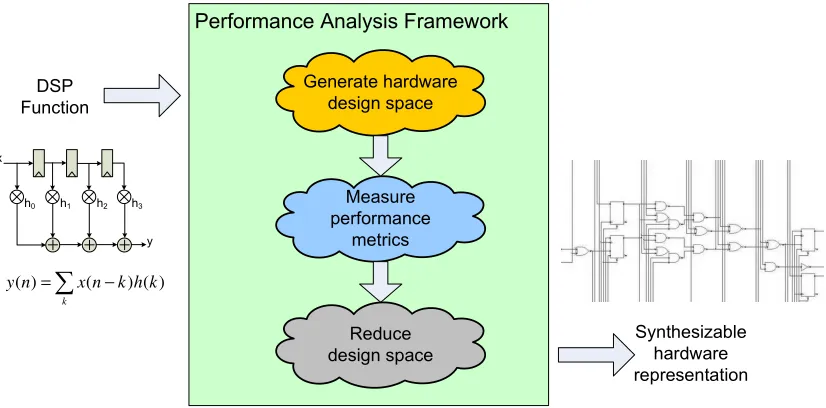
The goal of our performance analysis framework (PAF) is to efficiently generate, synthesize, and analyze the performance of different hardware representations for basic DSP algorithms. Additionally, our framework provides both algorithm developers and hardware designers cost functions that quantify the quality of a hardware design in terms of area, throughput, and power dissipation. The cost functions can be used to guide the designer in selecting a hardware implementation that performs well for certain design constraints. We accomplished these goals by defining a simplified user interface that paves a fast path to higher quality hardware designs for important DSP algorithms. We developed our method-ology for designing and analyzing computationally intensive hardware designs that target ASICs. The concepts introduced in the development of this work are extendible to other hardware platforms such as FPGAs. Figure 3.1 illustrates a top-level view for the fun-damental structure behind the development of our PAF in refining a DSP function to a synthesizable hardware design.
! " # $
− =
k
k h k n x n
y( ) ( ) ( )
Figure 3.1: Concept of the Performance Analysis Framework
wishes to refine and provides several high-level design parameters that guide the framework in generating application-specific architectures that meet design constraints. Additionally, we provided cost functions to the designer that assess the quality of hardware designs gen-erated using our framework. This is an advantage over other design tools and frameworks. This chapter presents the details of our PAF for generating the hardware design space for a computationally intensive DSP algorithm such as an FIR filter. We begin by introducing our PAF methodology and illustrate the steps involved in constructing hardware designs and guiding the designer through the process of searching the design space. We then describe the pertinent hardware performance metrics and highlight a subset of cost functions used for evaluating the quality of hardware designs generated by our framework. Finally, we identify the different design options provided for the designer when considering efficient hardware representations for DSP applications.
3.1
Performance Analysis Framework Methodology and Flow
overall design productivity by generating recognizable hardware structures that perform well while meeting specific design constraints defined by the user. Additionally, the goal of this work was to significantly reduce synthesis times, allowing the designer to explore the hardware design space in hours versus weeks. This allowed the designer to investigate alternate hardware structures in a relatively short time, should the designer change or enhance the system specifications.
We developed a method for estimating the performance metrics for the designs and included cost functions in our framework that can be used to evaluate trade-offs between area, throughput, power dissipation and hardware latency. The final output of our frame-work is a reduced set of synthesizable hardware designs with improved performance metrics compared to general purpose, “commercial off-the-shelf” designs. The structure of the de-signs generated by our framework allows proficient hardware designers to apply additional optimizations at multiple levels of design abstraction; a key advantage for further improving the design performance. The PAF reduces the number of designs to be considered by the designer by eliminating those that do not meet the specification.
3.1.1 EDA Tools used for the PAF
We combined well-known design tools and scripting languages accepted by both DSP algorithm developers and hardware designers. Our purpose in selecting common EDA tools was to facilitate the use of our framework, as well as allow designers to expand the set of hardware designs within the frameworks library. We chose MATLAB as the interface between the user and the hardware designs generated by our framework since algorithm developers are more comfortable using MATLAB for efficiently and accurately modeling their signal processing algorithms at the algorithmic level. The data generated by the MATLAB algorithmic models were used as reference data for validating the functionality of the low-level designs. Additionally, MATLAB is a good choice of tools for numerically and graphically analyzing the design space in search for hardware designs that perform well. We accomplished this through the use of cost functions that assess the quality the hardware designs using one or more performance metrics. Our framework provided the designers the freedom to select the cost functions they need to assist them in searching the design space for hardware structures that met design specifications.
work. SystemC extends the capabilities of C/C++ by providing a set of class libraries capable of modeling designs at different levels of abstraction: from the algorithmic to the logic level [3] [14]. The main advantage of using SystemC in our work was to model the DSP algorithms at the architectural level, while using high-level data-types and communication interfaces in order to expedite the simulation process for the hardware designs. Our choice for using Verilog to model the hardware designs at the synthesizable RTL allowed designers to use our framework as the front end tool to their synthesis CAD tools. We chose the Synopsys Design Compiler for synthesizing the designs generated by our framework.
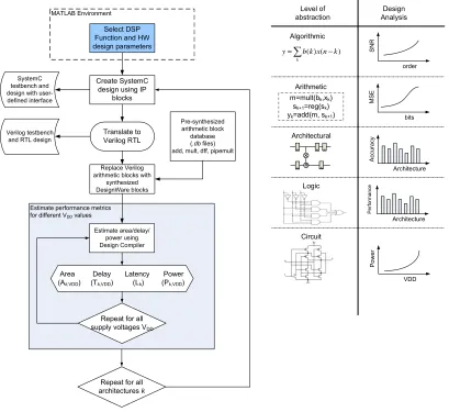
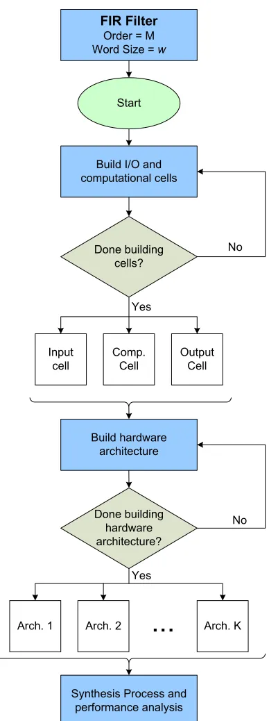
3.1.2 Framework Methodology and Flow
! " # $ ! % ! &
" #
' %' $
(
) % ! & ! " #
" * + , , , ( % ( -" # % ( " ! $ ! ) " ! % % % $ * , + * , + * + * , + ! " % ! ! ! ( − = k k n x k b
y ( )( )
. *"#,/#+ #01. *#+ %#. * , #01+
0 2 " ! % ! $
Figure 3.2: PAF Flow for refining a DSP algorithm and selecting an architecture
the signal processing algorithms considered in our work. We used the optimized Booth-recoded Wallace-tree multipliers and carry-look-ahead adders available in the Synopsys IP library. The same methodology can be used in cases where the user selects alternative circuits for the mathematical elements. The estimated performance results for the hardware designs obtained using the pre-synthesized cores were comparable to synthesizing the entire design [47]. The pre-synthesized cores significantly reduced synthesis times from tens of minutes to seconds for each design, depending on the complexity of the designs.
3.1.3 Hardware Design and Synthesis Process
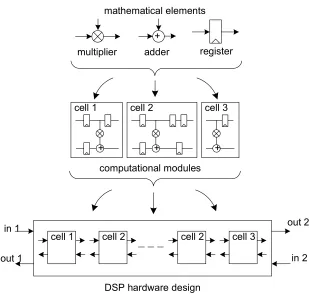
We employed a bottom-up, modular design methodology to construct the hard-ware structures included in our framework. Figure 3.3 illustrates a single iteration for constructing a hardware design using basic arithmetic hardware elements and processing modules. The designer initially selects the type of DSP function from our library of DSP functions in our framework. The user then selects high-level parameters from the options in our framework. As an example, a designer wishing to implement an FIR filter in hardware can select the filter order and word sizes from our framework GUI. The user presses a but-ton and our framework proceeds to generate each hardware design starting with common and well recognized filter structures. Scripts in our framework begin the design process by constructing the basic computational modules. The processing modules consist of the necessary instantiations of mathematical elements such as adders, multipliers and delay units.
Figure 3.3: Bottom-up modular design for a single hardware structure
! "
# $
% #
& '
(
)
&
(
)
![Figure 1.2: Flexibility vs. efficiency , source [7]](https://thumb-us.123doks.com/thumbv2/123dok_us/1633613.1203758/21.612.120.527.94.378/figure-flexibility-vs-eciency-source.webp)