calculation in characteristic three
T. Kerins1, W. P. Marnane1, E. M. Popovici2, and P.S.L.M. Barreto3 1
Dept. of Electrical and Electronic Engineering, University College Cork, Cork City, Ireland.
{timk,liam}@rennes.ucc.ie
2 Dept. of Microelectronic Engineering,
University College Cork, Cork City, Ireland. [email protected]
3
Dept. Computing and Digital Systems Engineering Escola Polit´ecnica, Universidade de S˜ao Paulo
S˜ao Paulo, Brazil. [email protected]
Abstract. In this paper the benefits of implementation of the Tate pair-ing computation in dedicated hardware are discussed. The main obser-vation lies in the fact that arithmetic architectures in the extension field
GF(36m) are good candidates for parallelization, leading to a similar
cal-culation time in hardware as for operations over the base fieldGF(3m).
Using this approach an architecture for the hardware implementation of the Tate pairing calculation based on a modified Duursma-Lee algorithm is proposed.
keywordsTate pairing, hardware, characteristic three, tower fields
1
Introduction
In recent years an ever increasing number of pairing based cryptosystems have appeared in the literature, see [1]. In turn this has driven research into efficient algorithms for the implementation of bilinear pairings on elliptic curves. To date the Tate pairing (originally introduced to cryptography by Frey and R¨uck in [2]) has attracted attention as the most efficiently computable bilinear pairing on elliptic curves and over supersingular elliptic curves it achieves its maximum security in characteristic three
as well as a triple-and-add algorithm in characteristic three greatly simplifies the pairing calculation. The utilization of so called tower fields of GF(3m) for arithmetic inGF(36m) was originally proposed by Galbraithet al.[4].
In 2003 further improvements in the implementation of the Tate pairing were described by Duursma and Lee in [7], leading the DL algorithm for Tate pair-ing computation. Here the pairpair-ing computation was extended to more general hyperelliptic curves. Also the distortion map was incorporated into the oper-ation of into the algorithm itself, as well as as well as modifying the loop of the BLKS/GHS algorithms, to yield a more efficient implementation. Further enhancements to the DL algorithm for supersingular elliptic curves over fields of characteristic three were described in [9], [10] and [11]. As will be described in this paper this modified DL (MDL) algorithm described in [9] is an excel-lent candidate for implementation on dedicated hardware. Further work on even more efficient general pairing algorithms of which the MDL algorithm is a special case appeared recently in [12]
Despite the large body of work accumulating regarding the improving algo-rithmic efficiency of the Tate pairing computation to date the hardware imple-mentation of such algorithms particularly over characteristic three has received scant attention in the literature. This is somewhat surprising given the well known speed and security advantages of dedicated cryptographic hardware [13]. The main contribution of this paper is the description of how the modified DL algorithm in characteristic three can be efficiently implemented in hardware and a number of conclusions are then derived about the expected calculation time of such an architecture.
This paper is organized as follows. Section 2 describes related work on the hardware implementation of Tate pairing and arithmetic circuitry in character-istic three. Section 3 describes the modified MDL algorithm for computation of the Tate pairing and issues related to its efficient the hardware implementation. Section 4 discusses feasibility and calculation time on dedicated hardware. The conclusions of this paper are presented in Section 5.
2
Related Work
performed in hardware by small combinational gate circuits using various two bit binary encoding of GF(3) elements and that the gate delay for these addi-tion and subtracaddi-tion architectures is low. This implies that additive operaaddi-tions in GF(3m) arithmetic hardware can be performed almost for free and will not significantly contribute to a processor’s calculation time. In hardware elements ofGF(3m) can be represented in 2mbits.
In [15] a digit serial multiplier overGF(3m) is described. This considers mul-tiplication over GF(3m) as a series of matrix-vector multiplications with coeffi-cients inGF(3). This can also be implemented efficiently in hardware assuming a low weight irreducible polynomialf(x)∈GF(3)[x] (trinomial or pentanomial) has been used to define arithmetic in GF(3m). Under this assumption cubing circuitry inGF(3m) can also be efficiently implemented in much less hardware than general multiplication and cubing can be performed in a single clock cycle. An efficient algorithm and hardware architecture for inversion inGF(3m) in 2m clock cycles based on the extended Euclidean algorithm appeared recently in [16] and [17].
Few full hardware processor architectures for Tate pairing calculation in char-acteristic three have appeared in the literature. However, the authors are aware of an FPGA implementation of a pairing based cryptosystem coprocessor archi-tecture based on the binary BLKS/GHS algorithm in [19].
3
Tate Pairing Calculation by Modified Duursma-Lee
Algorithm
This section presents an outline of the modified Duursam-Lee algorithm along with some observations regarding its efficient calculation in hardware.
3.1 The Tate Pairing
Following from [5], [8] and [12] the modified Tate pairing is defined on the su-persingular elliptic curve E± in affine coordinates defined over a Galois field
GF(3m) where in practicemis generally prime
E±:y
2
=x3−x±1 (1)
The set of points onE±along with the point at infinityOform a group of order
#E under the well known chord-tangent law of composition [20]. The curve (1) is chosen so that it contains a large cyclic subgroup of prime order l, i.e.
l = #E/n, wherenis small. Alsol2
does not divide #E but l divides 36m−1 and not any 3jm−1,j <6. In order to resist discrete logarithm solving attacks it is recommended that the binary representation of l is at least 150 bits long [21].
NowE±(GF(3m)) contains anl-torsion groupE±[l](GF(3m)) and similarly
E±(GF(36m)) contains an l torsion group E±[l](GF(36m)). Following [5] for
E±[l](GF(3m)) and E±[l](GF(36m)) to an element of the multiplicative
sub-group of GF(36m), i.e.GF(36m)∗
E±[l](GF(3m))×E±[l](GF(36m))→GF(36m) ∗
(2) It is only defined up tolthpowers of unity; to obtain a unique value inGF(36m) suitable for cryptographic applications it is necessary to raise it to the power
²= (36m−1)/l.
Now considerP = (xp, yp), R= (xr, yr)∈E±[l](GF(3m)), i.e.xp, yp, xr, yr∈
GF(3m). The pairing is efficiently computed in practice by considering the point
φ(R)∈E±[l](GF(36m)) where φ is a distortion map of the type introduced in
[6]. The distortion mapφis defined as
φ(R) =φ((xr, yr)) = (ρ−xr, σyr) (3) whereρ, σ∈GF(36m) such thatρ3−ρ∓1 = 0, (ρ3−ρ−1 = 0 forE
+ (1) and
ρ3−ρ+ 1 = 0 forE
− (1)) andσ2+ 1 = 0. Following [7–9] the the modified Tate
pairing is now defined on pointsP, R∈E[l](GF(3m)) as ˆ
e(P, R) =e33m−1(P, φ(R))²
1 =el(P, φ(R))²=τ ∈GF(36m) (4)
The calculation of (4) is performed in two stages :
– Evaluation of point φ(R) ∈ E±[l](GF(36m)) in the rational function fP onE±(GF(3m)) such that div(fp) ∼l((P)−(O)), i.e. e33m−1(P, φ(R)) =
fp(φ(R)) = t ∈ GF(36m)∗
This is performed by modified Duursma-Lee algorithm illustrated as Algorithm 1
– Raising the resultingt∈GF(36m) element to the Tate power²
1, i.e.τ=t²1. Tate power ²1 =²/33m = 33m−1 as the DL algorithm benefits from the equivalence property of the Tate pairing.
Algorithm 1: The Modified Duursma-Lee Algorithm (char 3) input:P = (xp, yp), R= (xr, yr)∈E±[l](GF(3m))
output:t=e33m−1(P, φ(R)))∈GF(3 6m)∗
01. initialize :t, γ,∈GF(36m),
α=xp, β=yp, x=x3r, y=y 3
r, µ= 0∈GF(3m)
d= (±m) mod 3∈GF(3) (* +m↔E+,−m↔E− *)
02. foriin 0 tom−1 loop
03. α=α9,β=β9 (* arithmetic inGF(3m) *) 04. µ=α+x+d (* arithmetic inGF(3m) *)
05. γ=−µ2−βyσ−µρ−ρ2 (* arithmetic inGF(36m) *) 06. t=t3 (* cubing inGF(36m) *)
07. t=tγ (* multiplication inGF(36m) *) 08. y=−y (* arithmetic inGF(3m) *)
09. d= (d∓1) mod 3 (* d=d−1↔E+,d=d+ 1↔E− *)
After the calculation of t = e33m−1(P, φ(R))) ∈ GF(3
6m) by Algorithm 1 this Galois field element must then be raised to the power²1. This can be effi-ciently performed by representing GF(36m) as an extension field ofGF(3m) as illustrated in Section 3.2.
3.2 A Tower field representation for GF(36m )
As discussed in Section 2, efficient hardware architectures exist for addition, sub-traction, cubing and multiplication in the base field GF(3m). However as seen from Algorithm 1 the principal complexity in performing the modified Tate pair-ing (4) lies in the implementation of efficient arithmetic inGF(36m) as well as
GF(3m). The suggestion of constructing the fieldGF(36m) as an extension field ofGF(3m) originally appeared in [4] and [5] and is prudent for hardware imple-mentation. In [11] much of the arithmetic developed in this section is explicitly described.
The choice of basis for construction forGF((36m)) fromGF(3m) is motivated by a desire to simplify as much as possible theGF(36m) elementsρandσused in the distortion map φ (3) appearing in steps 05. of Algorithm 1. Elements of a ∈ GF(36m) are represented as a = P5
i=0aiζi where ai ∈ GF(3m). The basis {ζ0
, ζ1
, ζ2
, ζ3
, ζ4
, ζ5
} = {1, σ, ρ, σρ, ρ2
, σρ2
} is equivalent to a tower field extension ofGF((3m)6
)∼=GF(((3m)2 )3
) whereσandρare zeros of σ2
+ 1 = 0 andρ3
−ρ∓1 as defined by the distortion map i.e.
GF(32m)∼
=GF(3m)[y]/g(y) (5)
whereg(y) =y2+ 1 is an irreducible polynomial overGF(3m) (provided that m and 2 are coprime) and
GF(36m)∼=GF(32m)[z]/h
±(z) (6)
whereh±(z) =z3−z∓1 is an irreducible polynomial overGF(32m). Polynomial
h+(z) =z3−z−1 is used forE+ andh−(z) =z3−z+ 1 forE− (1) provided
thatm and 3 are coprime.
In this basis the elementsGF(36m) elementsσandρrequired by the distor-tion map so that σ2+ 1 = 0 ∈ GF(36m) and ρ3−ρ∓1 = 0 ∈ GF(36m) are represented by
σ= 0ζ0 + 1ζ1
+ 0ζ2 + 0ζ3
+ 0ζ4 + 0ζ5
= (0,1,0,0,0,0)
and
ρ= 0ζ0 + 0ζ1
+ 1ζ2 + 0ζ3
+ 0ζ4 + 0ζ5
= (0,0,1,0,0,0)
Now implementation of multiplication byσand ρin steps 05. of Algorithm 1 now becomes much simpler in hardware. Consider calculation ofγ∈GF(36m)
γ=−µ2−βyσ−µρ−ρ2
Now calculation of γ involves only two multiplications of µ2
and βy in the
GF(3m) subfield which can be carried out in parallel. The GF(3m) negation operation does not need to be clocked can be carried out by a small amount of combinational gate circuitry. Calculation ofµ from step 04. of Algorithm 1. requires only addition over GF(3m) which can also be carried out un-clocked using a small amount of combinational logic. Multiplication of the respective
GF(3m) elements by ζ in (7) can be performed by a simple rewiring in hard-ware. As elements ofGF(3m) are represented by 2mbits in hardware elements ofGF(36m) are represented in 12mbits.
A further advantage of using this representation from a hardware perspective is that cubing and full multiplication in GF(36m) (steps 06., 07. Algorithm 1) can also be performed using only simpler cubing and multiplication operations respectively over the base fieldGF(3m) and similarly all these simpler operations can be carried out in parallel.
Multiplication Consider multiplicationc=abof two elementsa=P5i=0aiζ i
andb=P5j=0bjζj ofGF(3
6m) wherea
i, bj ∈GF(3m). In the equivalent tower field representation from (5) and (6) elements a∈GF(36m) are represented of triples of elements ofGF(32m)
a= (a0+a1σ)
| {z }
˜ a0
+ (a2+a3σ)
| {z }
˜ a1
ρ+ (a4+a5σ)
| {z }
˜ a2
ρ2
In this representation multiplication of GF(36m) elements a = P2
i=0˜aiρi and
b=P2j=0˜bjρ j, ˜a
i,˜bj∈GF(32m) is performed by Karatsuba multiplication [22] of a and b over GF(32m) to form a degree 4 polynomial d = P4
k=0d˜kρ k over
GF(22m)
˜ d0 ˜ d1 ˜ d2 ˜ d3 ˜ d4 = ˜
a0˜b0
(˜a1+ ˜a0)(˜b1+ ˜b0)−˜a1˜b1−˜a0˜b0 (˜a2+ ˜a0)(˜b2+ ˜b0) + ˜a1b˜1−˜a2˜b2−˜a0˜b0
(˜a2+ ˜a1)(˜b2+ ˜b1)−˜a2˜b2−˜a1˜b1 ˜
a2˜b2
(8)
Polynomial d from (8) is then reduced modulo the irreducible polynomial
h±(z) (6) over GF(32m) to form c=P
2 i=1˜ciρ
i as illustrated in (10) forh +(z) and (10) in forh−(z)
˜ c0 ˜ c1 ˜ c2 = ˜
d0+ ˜d3 ˜
d1+ ˜d3+ ˜d4 ˜
d2+ ˜d4
(9) ˜ c0 ˜ c1 ˜ c2 = ˜
d0−d˜3 ˜
d1+ ˜d3−d˜4 ˜
d2+ ˜d4
(10)
As seen from (8) the composition stage of multiplication inGF(36m) is performed in six multiplications, seven additions and six subtractions inGF(32m) while the reduction stage is performed in either five additions for h+(z) (10) or three ad-ditions and two subtractions for h−(z) in GF(32m). Addition and subtraction
hardware using arrays of simple gate circuits previously discussed. The hardware complexity inGF(36m) multiplications lies in the required six multiplications in
GF(32m). From the dataflow diagram for (8) illustrated as Figure 1 is is seen that the six requiredGF(32m) multiplications can be carried out in parallel.
Fig. 1. Dataflow for Karatsuba composition stage of multiplication in GF(36m) ∼
=
GF(32m)[z]/h±(z)
Multiplication ˜c = ˜a˜b ∈ GF(32m) (5) of two elements ˜a = a
0+σa1 and ˜
b=b0+σb1, a1, a0, b1, b0 ∈GF(3m) is performed by Karatsuba multiplication in three multiplications, two additions and three subtractions in GF(3m) as illustrated in (11)
·
c0
c1
¸
=
·
a0b0−a1b1
(a1+a0)(b1+b0)−a1b1−a0b0
¸
(11)
Here both the polynomial composition and reduction steps are performed simul-taneously by the observation that σ2 = −1 ∈ GF(22m) from g(y) (5). Again additive operations inGF(3m) are easily performed by simple gate circuits and multiplication inGF(3m) can be performed as discussed in Section 2. As illus-trated from Figure 2 the three requiredGF(3m) multiplications can be carried out in parallel.
This implies that by this method multiplication inGF(36m) requires eighteen multiplications in the base field GF(3m) plus a number of additive operations. The advantage of implementing this operation in dedicated hardware over serial general purpose processors lies in the fact that all eighteenGF(3m) multiplica-tions can be carried out in parallel. By parallelizing this operation the calculation time for multiplication in GF(36m) can be made very close to that for that in
Fig. 2.Dataflow for Karatsuba multiplication inGF(32m)∼
=GF(3m)[y]/(y2
+ 1)
an extra few clock cycles. So using the digit serial multiplier of Bertoni et al. [15] in hardware implementation of multiplication inGF(36m) can be performed in dm/De+nm clock cycles, wherenm is the relatively small number of extra clocks required for scheduling the additions/subtractions and register read/write operations.
Cubing Cubing c = a3
∈ GF(36m) ∼= GF(32m)[z]/h
±(z) (6) of an element
a =P2i=0˜aiρi,˜ai ∈ GF(3
2m) is performed by (12) for GF(36m) generated by polynomialh+(z) and by (13) forGF(36m) generated by polynomialh−(z).
˜ c0 ˜ c1 ˜ c2 = ˜ a3 0+ ˜a
3 1+ ˜a
3 2 ˜
a3 1−˜a
3 2 ˜ a3 2 (12) ˜ c0 ˜ c1 ˜ c2 = ˜ a3 0−˜a
3 1+ ˜a
3 2 ˜
a3 1+ ˜a
3 2 ˜ a3 2 (13)
Each involves three cubing operations, two additions and a subtraction in
GF(32m). As illustrated in Figures 3 and 4 in both cases the three GF(32m) cubing operations can be carried out in parallel.
Fig. 3.Dataflow for cubing inGF(36m)∼
=GF(32m)[z]/h +(z)
From (12) and (13) main complexity in cubing inGF(36m)∼=GF(32m)[z]/h
±(z)
Fig. 4.Dataflow for cubing inGF(36m)[z]∼
=GF(32m)[z]/h−(z)
wherea1, a0∈GF(3m). Now ˜c=c0+σc1= ˜a3∈GF(32m) is calculated by
·
c0
c1
¸
=
·
a3 0
−a3 1
¸
(14)
which involves two cubing operations inGF(3m) which again can be performed in parallel. So the cubing operation in GF(36m) can be efficiently calculated in hardware by performing six GF(3m) cubing operations in parallel as well as three GF(3m) negation operations and six addition/subtraction operations. Following from [15]GF(3m) cubing can be performed efficiently in a single clock cycle and the additive operations can be performed by simple combinational gate circuits. Using this type of parallel cubing architecture with six GF(3m) cubing circuitsGF(36m) cubing is performed in a single clock cycles and the six additive operations are performed by simple un-clocked gate circuits previously discussed.
Raising to Tate Power The basis{ζ0, ζ1, ζ2, ζ3, ζ4, ζ5}={1, σ, ρ, σρ, ρ2, σρ2} of GF(36m) over GF(3m) described by the distortion map as previously dis-cussed is converted to the other basis{ξ, ξi, ξ2, ξ3, ξ4, ξ5} = (1, ρ, ρ2, σ, σρ, σρ2) described by the distortion map by a simple rewiring in hardware as illustrated in Figure 5 . This is analogous to the tower field representation
Fig. 5.Hardware rewiring forGF(36m) basis change from{ζ
GF(33m)∼=GF(3m)[y]/h
±(y) (15)
where h±(y) = y3−y∓1 is an irreducible polynomial over GF(3m) (E+ ↔
h+, E− ↔h−)
GF(36m)∼=GF(33m)[z]/g(z) (16) whereg(z) =z2+ 1 is an irreducible polynomial overGF(33m).
In this basisa∈GF(36m) is represented a pair of elements ˇa
0,ˇa1∈GF(33m)
a= (a0+a1ρ+a2ρ 2
)
| {z }
ˇ a0
+ (a3+a4ρ+a5ρ 2
)
| {z }
ˇ a1
σ
As described in [11] raisinga =P5i=0aiξi ∈GF(36m) to the Tate power ²1 = 33m−1 in this basis can be performed in a much more efficient manner that typical multiply-and-accumulate methods of exponentiation by the observation that formodd
a33m
= (ˇa0+σˇa1) 33m
= ˇa0−σˇa1 (17)
asσ2=−1∈GF(33m). Thus (17) implies thatc=a²1∈GF(36m) is calculated
by
c= ˇc0+σcˇ1= ˇ
a0−σˇa1 ˇ
a0+σˇa1
=£1 + ˇa2 1ν
−1¤
+σ£1−(ˇa0+ ˇa1)2ν−1
¤
(18)
whereν = (ˇa2 0+ ˇa
2
1)∈GF(3
3m). Thus raising to the Tate power²
1 involves five multiplications, three additions and a subtraction and an inversion inGF(33m). Multiplication in the field GF(33m) (15) is carried out in a similar manner to that outlined in (8),(9) and (10) except in this case the base field is GF(3m). The six required GF(3m) multiplications can be carried out in parallel and the additive operations are carried out by the gate circuits previously discussed. The calculation time for multiplication inGF(33m) is given asdm/De+nm. Inversion in GF(33m) is carried out by arithmetic inGF(3m) as illustrated in Appendix A. As this operation is performed only once it does not require to be heavily parallelized.
4
A Hardware Architecture for Tate Pairing Calculation
based on Duursma-Lee Algorithm
This section considers a prospective hardware implementation for Tate pair-ing calculation ˆe(P, R) = τ (4) over elliptic curves (1) based on Algorithms 1 considering the observations from Section 3.2 on the efficient calculation time achievable by parallelizingGF(36m) arithmetic.
4.1 Observations on the Modified Tate Pairing Calculation
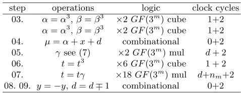
and six GF(3m) cubing circuits are available in parallel, along with a suitable amount of simplerGF(3m) arithmetic circuits for performing addition, subtrac-tion and negasubtrac-tion. Also required on such an architecture are 2mbit registers for storage of elements ofGF(3m) and 12m bit bus lines for elements ofGF(36m) elements. The calculation time for an iteration of Algorithm 1 using this type of architecture is illustrated in Table 1. An extra two clock cycles are added to the calculation time of each operation for register read/write operations.
Table 1.Number of clock cycles required for an iteration of the Modified Duursma-Lee algorithm implemented on a parallelGF(3m) hardware architecture
step operations logic clock cycles
03. α=α3,β=β3 ×2GF(3m) cube 1+2
α=α3
,β=β3
×2GF(3m) cube 1+2
04. µ=α+x+d combinational 0+2 05. γsee (7) ×2GF(3m) mul d+ 2
06. t=t3
×6GF(3m) cube 1 + 2
07. t=tγ ×18GF(3m) mul d+n m+2
08. 09. y=−y,d=d∓1 combinational 0+2
From Table 1 the modified Duursma-Lee Algorithm, Algorithm 1., can be performed on the type of dedicated hardware discussed in Section 3 in θDL =
m(2dm/De+ 17 +nm) clock cycles. Aftere33m−
1(P, φ(R)) =t∈GF(36m) has been performed by Algorithm 1. it is then necessary to raise thisGF(36m) element to the Tate power²
1 by (18) to generate the required unique resultτ=t²1 ∈GF(36m). This operation can be
efficiently performed on much of the same underlying hardware as required for Algorithm 1. The only operations required are multiplication, and additive oper-ations and a single inversion in the base field GF(3m). Performing theGF(3m) multiplications as required in parallel implies that (18) can be performed in
θT P = 9(dm/De+nm) + 2mclock cycles.
Assuming a worst case situation where the register read/write operations and scheduling through the simple gate circuits take the same number of clock cycles as a multiplication operation (i.e. nm ≈ dm/De) this implies that using this type of hardware architecture the number of clock cycles for calculation of (4) is given by
θT AT E≈ θDL + θT P
≈m(2dm/De+ 17 +nm) + 9(dm/De+nm) + 2m
≈ 3m(dm/De+ 17) + 18dm/De+ 2m
(19)
4.2 Implementation Aspects
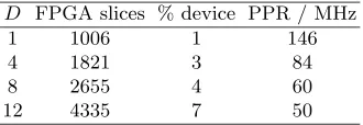
the main arithmetic units the GF(3m) multiplier and cubing cores were cap-tured in the VHDL hardware design language and prototyped on the Xilinx Virtex2Pro125 device [23] for the fieldGF(397)∼
=GF(3)[x]/x97+x16+ 2. The FPGA resource usage (in FPGA slices : total on device 55616) and the post place-and-route (PPR) clock frequency of theGF(397) digit serial multiplier are illustrated for digit sizesD= 1,4,8,12 in Table 2.
Table 2.PrototypeGF(397
) digit serial multiplier implementation results on the Xilinx Virtex2Pro technology
D FPGA slices % device PPR / MHz
1 1006 1 146
4 1821 3 84
8 2655 4 60
12 4335 7 50
The fastGF(397) cubing circuitry was also implemented on this target tech-nology and occupied 514 slices (0.5%) and had a post place-and-route clock frequency of 118 MHz. TheGF(3m) inverter architecture achieved a clock fre-quency of 62 MHz and occupied 2210 (4 % device) FPGA slices.
These preliminary results indicate that eighteen GF(397) multipliers with a digit size of D = 4 can be implemented on approximately 60% of the target device and the sixGF(397
) cubing circuits and inversion circuit on approximately 7% of the device. This leaves the remaining 33% of the target device for storage registers, control data-path and arrays of gate circuits for the simple GF(3m) addition and subtraction logic.
Using the pessimistic (19) for the required number of clock cycles this im-plies that calculation of (4) on E+ from (1) over GF(397) with a digit size of
D= 4 could be performed in 12,866 clock cycles. A conservative 10 MHz clock frequency on the target technology translates this into a calculation time of ap-proximately 1.3ms. This represents at least a three fold improvement over the calculation times of 4.05msand 4.33msreported recently for optimized software implementations of the same calculation on serial general purpose processors [11] [24].
5
Conclusions
In this paper the suitability of the modified Duursma-Lee (MDL) algorithm for implementation in dedicated hardware has been illustrated. Prudent choice of basis construction for the fields GF(36m) allows the efficient implementa-tion of multiplicaimplementa-tion and cubing operaimplementa-tions and only arithmetic in theGF(3m) subfield is required. Multiplication in GF(36m) can be performed by eighteen
with some combinational logic. This leads to a low number of clock cycles for arithmetic in GF(36m) compared to those required on serial processors. Mod-ern FPGA devices such as the Virtex2Pro currently have enough resources to contain an implementation of this type of parallel hardware for calculation of the MDL algorithm. Assuming pessimistic operating parameters this dedicated hardware is projected to at least third the calculation time currently possible using optimized software implementations.
References
1. R. Dutta, R. Barua and P. Sarkar. Pariring-based cryptography : A survey. Cryp-tology ePrint Archive, Report 2004/064 2004.http://eprint.iacr.org/2004/64. 2. G. Frey and H. R¨uck. A remark considering m-divisibility in the divisor class group
of curves.Mathematics of Computation,62:865-874, 1994.
3. V. S. Miller. Short Programs for functions on curves. Unpublished manuscript. 1986. http://crypto.stanford.edu/miller/miller.pdf.
4. S. Galbraith, K. Harrison and D. Soldera. Implementing the Tate pairing. In Al-gorithm Number Theory Symposium - ANTS V, volume 2369 of Lecture Notes in Computer Science, pages 324-337. Springer-Verlag 2002.
5. P.S.L.M. Barreto, H.Y. Kim, B. Lynn and M. Scott. Efficient implementation of pairing based cryptosystems. In Advances in Cryptology - CRYPTO’2002volume 2442 ofLecture Notes in Computer Science, pages 354-368. Springer-Verlag 2002. 6. E. R. Verheul. Evidence that XTR is more secure than supersingular elliptic curve
cryptosystems. InAdvances in Cryptology - Eurocrypt 2001volume 2045 ofLecture Notes in Computer Science, pages 195-210. Springer-Verlag 2001.
7. I. Duursma and H.-S. Lee. Tate pairing implementation for hyperelliptic curves
y2 = xp−x+d. In Advances in Cryptology - Asiacrypt 2003, volume 2894 of
Lecture Notes in Computer Science, pages 111-123. Springer-Verlag, 2003.
8. P. S. L. M. Barreto. The well-tempered pairing. Bochum, Germany 2004. 8th Work-shop on Elliptic Curve Cryptography - ECC’2004. Invited talk.
9. S. Kwon. Efficient Tate pairing computation for supersingular elliptic curves over binary fields. Cryptology ePrint Archive, Report 2004/303, 2004. http://eprint.iacr.org/2004/303.
10. M. Scott and P. S. L. M. Barreto. Compressed Pairings. In Advances in Cryp-tology CRYPTO’2004 volume 3152 of Lecture Notes in Computer Science, pages 140-156. Springer-Verlag, 2004. Updated version: Cryptology ePrint Archive, Re-port 2004/032.http://eprint.iacr.org/2004/303
11. R. Granger, D. Page and M. Stam. On Small Characteristic Algebraic Tori in Pairing-Based Cryptography. Cryptology ePrint Archive, Report 2004/132, 2004. http://eprint.iacr.org/2004/132
12. P. S. L. M. Barreto, S. Galbraith, C. O hEigeartaigh and M. Scott. Efficient Pair-ing Computation on SupersPair-ingular Abelian Varieties. Cryptology ePrint Archive, Report 375/2004. 2004.http://eprint.iacr.org/2004/375.
13. B. Schneier.Appplied Cryptographysecond edition. John Wiley & Sons, 1996. 14. D. Page and N. P. Smart. Hardware implementation of Finite Fields of
15. G. Bertoni, J. Guajardo, S. Kumar, G. Orlando C. Paar and T. Wollinger. Effi-cientGF(pm) Arithmetic Architectures for Cryptographic Applications. InTopics
in Cryptology - CT RSA 2003volume 2612 ofLecture Notes in Computer Science pages 158-175. Springer-Verlag 2003.
16. T. Kerins, E. Popovici and W. P. Marnane. Algorithms and Architectures for use in FPGA implementations of Identity Based Encryption Schemes. In Field Pro-grammable Logic and Applications- FPL 2004 volume 3203 of Lecture Notes in Computer Science, pages 74-83, Springer-Verlag 2004.
17. T. Kerins, W. P. Marnane and E. M. Popovici. Hardware Architectures for Arithemtic inGF(pm) for use in Public Key Cryptography. Preprint. 2004.
18. R. Granger, D. Page and M. Stam. Hardware and Software Normal Basis Arithemtic for Paring Based Cryptography in Characteristic Three. Cryptology ePrint Archive, Report 157/2004. 2004.http://eprint.iacr.org/2004/157. 19. T. Kerins, W. P. Marnane, E. M. Popovici and P. S. L. M. Barreto. A Hardware
Accelerator for Pairing Based Cryptosystems. Preprint. 2004.
20. J. H. Silverman.The Arithemtic of Elliptic Curves. Number 106 in Graduate Stud-ies in Mathematics. Springer-Verlag, Berlin, Germany, 1986.
21. I. Blake, G. Seroussi and N. Smart.Elliptic Curves in Cryptographyvolume 265 of London Mathemtatical Lecture Note Series, Cambridge University Press, 1999. 22. A. Karatsuba and Y. Ofman. Multiplication of Multidigit numbers on Automata.
Sov. Phys. Dokl (english translation), 7(7):595-596, 1963
23. Xilinx Inc. Virtex-2 Platform FPGAs : Complete Data Sheet. Ds031. 2004 http://www.xilinx.com/bvdocs/publications/ds031.pdf
24. P. S. L. M. Barreto. A note on efficient computation of cube roots in characteristic 3. Cryptology ePrint Archive, Report 035/2004 2004. http://eprint.iacr.org/2004/305.
Appendix A
Element ˇc=c0+c1ρ+c2ρ2= ˇa−1the inverse of ˇa=a0+a1ρ+a2ρ2∈GF(33m) is calculated efficiently by the observation that ˇcˇa= 1∈GF(33m). TheGF(3m) coefficients of ˇc ∈GF(33m) from defined by h
±(y) from (15) are calculated as
illustrated in (20) forh+(y) :
c0
c1
c2
=δ+−1
a2 0+a
2
2−a0a2−a1(a1+a2)
−a0a1+a22
a2
1−a0a2−a22
(20)
whereδ+= (a0−a2)a20+ (−a0+a1)a21+ (a0−a1+a2)a22and by (21) forh−(y)
:
c0
c1
c2
=δ−−1
a2 0−a
2
1+ (a1−a0)a2+a22
−a0a1−a22
a2
1−a0a2−a22
(21)
whereδ−= (a0−a2)a20+ (−a0−a1)a21+ (a0+a1+a2)a22∈GF(3m)
Calculation ofδ+ andδ−from (20) and (21) involves six multiplication
![Fig. 1. Dataflow for Karatsuba composition stage of multiplication in GF(36m) =∼GF(32m)[z]/h±(z)](https://thumb-us.123doks.com/thumbv2/123dok_us/1848097.1239811/7.595.182.434.187.328/fig-dataow-karatsuba-composition-stage-multiplication-gf-gf.webp)
![Fig. 2. Dataflow for Karatsuba multiplication in GF(32m) =∼ GF(3m)[y]/(y2 + 1)](https://thumb-us.123doks.com/thumbv2/123dok_us/1848097.1239811/8.595.223.394.481.582/fig-dataow-karatsuba-multiplication-gf-m-gf-m.webp)
![Fig. 4. Dataflow for cubing in GF(36m)[z] =∼ GF(32m)[z]/h−(z)](https://thumb-us.123doks.com/thumbv2/123dok_us/1848097.1239811/9.595.221.394.555.641/fig-dataow-for-cubing-gf-m-z-gf.webp)