A New Compact Microstrip UWB Power Divider with Triple
Notched Bands
Hai Zhang1 and Junding Zhao2, *
Abstract—In this paper, a novel compact ultra-wideband (UWB) power divider with triple-notched bands is investigated. Firstly, the initial UWB power divider is studied using a couple of square ring quad-mode resonators. Then, by embedding a pair of coupled triple-mode stepped impedance resonators (TMSIRs) into the initial UWB power divider, three desired notched bands are achieved. The central frequencies of the notched bands can be easily controlled by the electrical length of the TMSIRs. To validate the design theory, a novel compact UWB power divider with triple notched bands centered at frequencies of 3.7 GHz, 5.2 GHz and 7.8 GHz is designed and measured. The simulated and measured results indicate that it has a low insertion loss and good return loss performance at all the three ports and a high isolation between the two output ports across the UWB bandwidth from 3.1 to 10.6 GHz.
1. INTRODUCTION
Power dividers play an important role in communication systems, such as transceivers, phase arrays, and power amplifiers, due to its ease of design and good performance. The most popular power divider is the Wilkinson power divider, which obtains completely matched output ports with sufficiently high isolation between them. However, it has less than 20% fractional bandwidth. With the rapid growth of unlicensed use of ultra-wideband (UWB) for radar imaging system and indoor wireless communications systems, there has been tremendous interest in exploration of various UWB components allocated 3.1∼10.6 GHz band. To achieve this goal, a few typical methods to design UWB power dividers have been developed so far [1–5]. In [2], to obtain wider bandwidth, multi-section Wilkinson power dividers have to be cascaded, which increases the size and the insertion loss. In [3], the waveguide power divider with high power capacity and very low insertion loss is designed. However, the waveguide structure is large and inflexible. In [4], the parallel-coupled lines and stepped-impedance open-circuited stubs are directly cascaded to construct UWB power dividers, which will increase fabrication cost. In [5], the multilayer broadside-coupled structure is used to obtain a compact UWB performance, but the multi-layer structure is hardly compatible with the existing microwave-integrated circuit. What is more, the existing wireless networks such as 3.7 GHz WiMAX band, 5.2 GHz WLAN band, and 7.8 GHz satellite communication band systems can easily interfere with UWB users. Thus, the compact UWB power divider with multiple notched bands is emergently required to reject these interfering signals.
In this paper, a novel compact ultra-wideband (UWB) power divider with triple-notched bands is proposed and designed. Firstly, the basic UWB power divider is designed based on the previous works [6, 7]. Then, by embedding a pair of coupled triple-mode stepped impedance resonators (TMSIRs) into the basic UWB power divider three desired notched bands are achieved. The central frequencies of the notched bands can be easily controlled by the electrical length of the TMSIRs. To validate the design concept, a novel compact UWB power divider with triple notched bands centered at frequencies
Received 4 August 2018, Accepted 6 September 2018, Scheduled 19 September 2018 * Corresponding author: Junding Zhao ([email protected]).
1 College of Information Science and Engineering, Huaqiao University, Xiamen 361021, China. 2 Nanjing Changfeng Aerospace
of 3.7 GHz, 5.2 GHz and 7.8 GHz is designed and measured. Both simulation and experimental results are provided with good agreement.
2. INITIAL UWB POWER DIVIDER
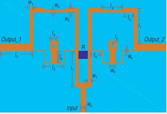
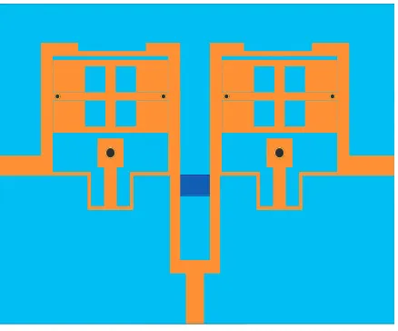
Figure 1 shows the layout of the proposed initial UWB power divider. All the dimensions are selected as follows: l0 = 6 mm, l1 = 5.7 mm,l2 = 2.9 mm,l3 = 4.4 mm,l4 = 2.1 mm,l5 = 4.1 mm,l6 = 2.0 mm, l7 = 5.7 mm, l8 = 1.5 mm, w0 = 1.1 mm, w1 = 0.7 mm, w2 = 0.7 mm, w3 = 0.5 mm, w4 = 0.1 mm, w6= 1.2 mm, w7 = 0.6 mm,r0 = 0.3 mm. The size of the whole circuit is 20 mm×30 mm.
Input
Output_1 Output_2
w
l
r
R
0 1
2 3 w
w
0
w0
4
5
6 7
w
w w l
l l
l
l
l l
2 3
6
7
4 8
l1
Figure 1. Layout of the proposed initial UWB power divider.
The measurement was carried out on the network analyser Agilent 85052D. The measured and simulated results are shown in Figure 2. As we can see from Figure 2, the fabricated UWB power divider has a passband from 2.1 GHz to 11.7 GHz. The return loss is under −10 dB and the insertion loss is close to 3 dB, which ensures the good transmission performance in the passband.
2 4 6 8 10 12
Frequency (GHz) 0
-10
-20
-30
-40
S
-parameters (dB)
Measured results Simulated results
3. TRIPLE-MODE SIR ANALYSIS
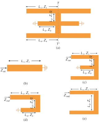
Figure 3(a) shows the geometry of the proposed TMSIR. It consists of two half-wavelength SIRs and two short-circuited stubs on its center plane. Since the resonator is symmetrical to theT-T′ plane, the odd-even-mode method is implemented. For odd-mode excitation, the equivalent circuit is one quarter-wavelength resonator with one end grounded, as shown in Figure 3(b). From the resonance condition of Yino = 0, the odd-mode resonant frequency can be deduced as:
fino= c
4L1√εeff
(1)
where fino is the center frequency of the notch band, εeff the effective dielectric constant, and c the
light speed in free space.
For even-mode excitation, the equivalent circuit is shown in Figure 3(c), which contains two resonant circuits: a quarter-wave-length resonator and a half-wavelength resonator, as shown in Figures 3(d)
(a)
(d) (e)
(b) (c)
T L , Z1 1
L , Z4 4 L , Z3 3
L , Z1 1
L , Z1 1
L , Z1 1 L , Z3 3
L , Z3 3
L , Z
/2
2
1
L , Z
/2
2
1
L , Z
/2
2
1
L , Z2
1
T '
Zin0
Zine1
Zine2 Zine
L , Z1 1
and (e). The even-mode resonant frequencies can be determined as follows:
fine1 =
c
4(L1+L2+L3)√εeff
(2)
fine2 =
c
(2L1+ 2L2+ 2L4)√εeff
(3)
where Z1 = Z3 = Z4 is assumed for simplicity. The resonance frequencies can be determined by the
electrical length.
The TMSIR can result in triple band-stop performance when being placed next to the microstrip line, and it can be equivalent to three shunt-connected series resonance circuits. The TMSIR can result
We3
(a) (b)
A
A '
Input Output
B '
B
w
L
e1
e1
Le2 Le2
we2
we4
Input Output
L
C
L L
C C
11 12 12
12 12
11
Figure 4. Geometry and equivalent circuit of the proposed coupled TMSIR.
(a) (b)
(c)
in triple band-stop (i.e., the triple notched-bands) performance when being placed next to the microstrip line, and it can be equivalent to three shunt-connected series resonance circuits, as shown in Figure 4. In this paper, the coupled TMSIR dimensions are selected as follows: we1 = 0.3 mm, we2 = 0.4 mm, we3= 1.1 mm,we4 = 0.1 mm,le1= 2.3 mm,le2 = 1.6 mm,le3= 1.5 mm.
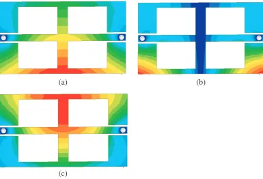
The figure shows that the current is more sparsely distributed as it nears the areas marked in blue, while its distribution grows denser in the red areas. Maximum and minimum values are set to be equal in order to allow an accurate comparison among Figures 5(a)–(c). Therefore, by appropriately adjusting the resonator dimensions, triple notched bands can be achieved at desired frequencies.
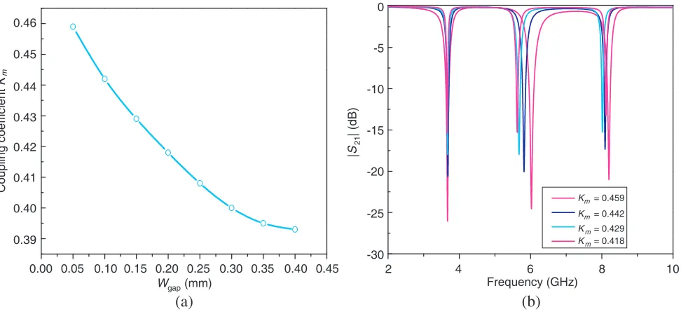
The bandwidth of the notched band can be controlled by tuning the coupling coefficientkm of the coupled TMSIR as illustrated in Figure 6. It should be mentioned that the coupling coefficient km is defined by:
km= f
2
notch-odd1−fnotch-even12
fnotch-odd12 +fnotch-even12 (4)
Referring to Figure 6(a), the coupling coefficient km decreases as increasing Wgap. Referring to
Figure 6(b), the stronger coupling between the TMSIR and the main transmission line is, the wider bandwidth of the notched band will be. Thus, the bandwidth of the notched band can be controlled by suitably shifting the coupling coefficient between the TMSIR and the main transmission line.
(a) (b)
0.00 0.05 0.10 0.15 0.20 0.25 0.30 0.35 0.40 0.45
W (mm)
gap
2 4 6 8 10
Frequency (GHz) 0.46
0.45
0.44
0.43
0.42
0.41
0.40
0.39
Coupling coefficient
K
m
0
-5
-10
-15
-20
-25
-30
|
S
| (dB)
21
K = 0.459
K = 0.442
K = 0.429
K = 0.418 m
m
m
m
Figure 6. (a) Simulated coupling coefficient km of the coupled TMSIR with different Wgap, (b)
simulated S-parameter of the bandwidth of notched bands with different coupling coefficient km of
the coupled TMSIR.
4. EXPERIMENTAL RESULTS
Figure 7. Layout of the proposed UWB power divider with triple notched bands.
2 4 6 8 10 12
Frequency (GHz) 0
-10
-20
-30
-40
S
-parameters (dB)
0 14
-50
|S |
|S |
|S |
|S |
|S |
|S |
11
21
31
22
23
33
Figure 8. Measured S-parameters of the designed UWB power divider with triple notched bands.
Figure 9. Photograph of the proposed UWB power divider with triple notched bands.
Figure 9 shows a photograph of the fabricated UWB power divider with triple notched bands. The overall size of the designed UWB power divider is only 20×30 mm2, which corresponds to a compact electrical size of 0.46λg×0.69λg. Comparisons with other reported UWB dividers with notched bands are listed in Table 1, demonstrates that the proposed UWB divider has good characteristics.
Table 1. Comparisons with other proposed UWB divider.
Ref. Circuit dimension Pass band (GHz) Insertion loss (dB) Notch Frequency (GHz)
[4] 3-D 3.5∼10.8 0.5 N/A
[5] 2-D 3.5∼10.1 0.4 N/A
[6] 3-D 3.1∼11.5 2.0 N/A
5. CONCLUSION
In this work, a high-performance UWB power divider with triple highly rejected notched bands using TMSIRs has been successfully implemented and investigated. Firstly, the initial UWB power divider is studied using a couple of square ring quad-mode resonators. Then, the characteristics of the proposed TMSIR are investigated by using even- and odd- mode analysis. Finally, by embedding a pair of coupled TMSIRs into the initial UWB power divider, three desired notched bands are achieved. The three notched-bands can be easily tuned to the desirable frequency location by controlling the parameters of the TMSIRs. The introduced TMSIRs is simple and flexible for blocking undesired narrow band radio signals appeared in UWB band. Using the advantage of small real estate, outstanding performance can be realised for broadband power divider, which is now widely demanded in UWB applications. To summarise, the proposed power divider is very useful for modern UWB wireless communication systems owing to its marked properties of simple topology, compact size, and excellent performance.
ACKNOWLEDGMENT
This work was supported by the Natural Science Foundation of Fujian Province, China (Grant No. 2017J01115), and the Undergraduate Education and Teaching Reform Project of Fujian Province, China (Grant No. FBJG20170151).
REFERENCES
1. Zhao, J. D., J. P. Wang, and J. L. Lin, “Compact UWB bandpass filter with triple notched bands using parallel U-shaped defected microstrip structure,” IET Electron. Lett., Vol. 50, No. 2, 89–91, 2014.
2. Lee, S. W., C. S. Kim, K. S. Choi, J. S. Park, and D. Ahn, “A general design formula of multi-section power divider based on singly terminated filter design theory,” IEEE MTTS-S Int. Microwave
Symp. Dig., Vol. 2, 1297–1300, Phoenix, AZ, USA, 2001.
3. Xue, Q. and K. Song, “Ultra-wideband coaxial-waveguide power divider with flat group delay response,” IET Electron. Lett., Vol. 46, No. 17, 1236–1237, 2010.
4. Wong, S. W. and L. Zhu, “Ultra-wideband power divider with good in-band splitting and isolation performances,” IEEE Microw. Wirel. Compon. Lett., Vol. 18, No. 8, 518–520, 2008.
5. Song, K.-J. and Q. Xue, “Novel ultra-wideband (UWB) multilayer slotline power divider with bandpass response,” IEEE Microw. Wirel. Compon. Lett., Vol. 20, No. 1, 13–15, 2010.
6. Wu, L., S. Wang, L. Li, and C. Tang, “Compact microstrip UWB power divider with dual notched bands using dual-mode resonator,” Progress In Electromagnetics Research Letters, Vol. 75, 39–45, 2018.