555-233-111
Comcode 108671405
Issue 2
June 2000
DEFINITY ONE
Communications System
Release 2.0
Notice
Every effort was made to ensure that the information in this book was complete and accurate at the time of printing. However, information is subject to change. Preventing Toll Fraud
Toll Fraud is the unauthorized use of your telecommunications system by an unauthorized party (for example, a person who is not a corporate employee, agent, subcontractor, or working on your company’s behalf). Be aware that there is a risk of toll fraud associated with your system and that, if toll fraud occurs, it can result in substantial additional charges for your telecommunications services. Lucent Technologies Fraud Intervention
If you suspect that you are being victimized by toll fraud and you need technical assistance or support, call the Technical Service Center’s Toll Fraud Intervention Hotline at 1-800 643-2353.
Providing Telecommunications Security
Telecommunications security (of voice, data, and/or video communications) is the prevention of any type of intrusion to (that is, either unauthorized or mali-cious access to or use of your company’s telecommunications equipment) by some party.
Your company’s “telecommunications equipment” includes both this Lucent product and any other voice/data/video equipment that could be accessed via this Lucent product (that is, “networked equipment”).
An “outside party” is anyone who is not a corporate employee, agent, subcontrac-tor, or working on your company’s behalf. Whereas, a” malicious party” is any-one (including someany-one who may be otherwise authorized) who accesses your telecommunications equipment with either malicious or mischievous intent. Such intrusions may be either to/through synchronous (time multiplexed and/or circuit-based) or asynchronous (character-, message-, or packet-based) equip-ment or interfaces for reasons of:
■ Utilization (of capabilities special to the accessed equipment)
■ Theft (such as, of intellectual property, financial assets, or toll -facility access)
■ Eavesdropping (privacy invasions to humans)
■ Mischief (troubling, but apparently innocuous, tampering)
■ Harm such as harmful tampering, data loss or alteration, regardless of motive or intent.
Be aware that there may be a risk of unauthorized or malicious intrusions associated with your system and/or its networked equipment. Also realize that, if such an intrusion should occur, it could result in a variety of losses to your company (including but not limited to, human/data privacy, intellectual property, material assets, financial resources, labor costs, and/or legal costs).
Your Responsibility for Your Company’s Telecommunications Security The final responsibility for securing both this system and its networked equipment rests with you - a Lucent customer’s system administrator, your telecommunications peers, and your managers. Base the fulfillment of your responsibility on acquired knowledge and resources from a variety of sources including but not limited to:
■ Installation documents
■ System administration documents
■ Security documents
■ Hardware-/software-based security tools
■ Shared information between you and your peers
■ Telecommunications security experts
To prevent intrusions to your telecommunications equipment, you and your peers should carefully program and configure your:
■ Lucent provided telecommunications system and their interfaces
■ Lucent provided software applications, as well as their underlying hardware/software platforms and interfaces
■ Any other equipment networked to your Lucent products
Rules. These limits are designed to provide reasonable protection against harmful interference when the equipment is operated in a commercial environment. This equipment generates, uses, and can radiate radio-frequency energy and, if not installed and used in accordance with the instructions, may cause harmful inter-ference to radio communications. Operation of this equipment in a residential area is likely to cause harmful interference, in which case the user will be required to correct the interference at his own expense.
Part 68: Network Registration Number. This equipment is registered with the FCC in accordance with Part 68 of the FCC Rules. It is identified by FCC regis-tration number AS593M-13283-MF-E. Refer to “Federal Communications Com-mission Statement” in “About This Book” for more information regarding Part 68.
Canadian Department of Communications (DOC) Interference Information
This digital apparatus does not exceed the Class A limits for radio noise emis-sions set out in the radio interference regulations of the Canadian Department of Communications.
Le Présent Appareil Nomérique n’émet pas de bruits radioélectriques dépassant les limites applicables aux appareils numériques de la class A préscrites dans le reglement sur le brouillage radioélectrique édicté par le ministére des Communi-cations du Canada.
Trademarks See “About This Book.” Ordering Information
Call: Lucent Technologies Publications Center
Voice 1 800 457-1235International Voice 317 361-5353 Fax 1 800 457-1764International Fax 317 361-5355 Write: Lucent Technologies Publications Center
P.O. Box 4100 Crawfordsville, IN 47933 Order: Document No. 555-233-111
Comcode 108671405 2, June 2000
For additional documents, refer to the section in “About This Book” entitled “Related Documents.”
You can be placed on a standing order list for this and other documents you may need. Standing order will enable you to automatically receive updated versions of individual documents or document sets, billed to account information that you provide. For more information on standing orders, or to be put on a list to receive future issues of this document, contact the Lucent Technologies Publications Center.
European Union Declaration of Conformity
The “CE” mark affixed to the DEFINITY ONE equipment described in this book indicates that the equipment conforms to the following European Union (EU) Directives:
■ Electromagnetic Compatibility (89/336/EEC)
■ Low Voltage (73/23/EEC)
■ Telecommunications Terminal Equipment (TTE) i-CTR3 BRI and i-CTR4 PRI
For more information on standards compliance, contact your local distributor. Comments
Contents
iii
Contents
Contents iii
About This Document xv
■ Purpose xv
■ Intended audience xv
■ Organization xvi
■ Conventions used in this book xvii
■ Typographic conventions xviii
■ Admonishments xix
■ Safety precautions xix
■ Security issues xx
■ Standards compliance xxi
■ Electromagnetic compatibility standards xxii
■ Trademarks and service marks xxiii
■ Related documents xxiv
■ Federal Communications Commission statement xxv
■ How to order documentation xxvii
■ How to comment on this book xxvii
■ Where to call for technical support xxviii
1
Maintenance Concepts forDEFINITY ONE 1-1
■ What’s New in DEFINITY ONE Release 2.0 1-1
■ Circuit packs 1-9
■ Maintenance objects 1-14
■ Alarm and error reporting 1-14
■ Maintenance testing 1-15
■ DEFINITY LAN Gateway maintenance 1-19
■ Processor C-LAN maintenance 1-23
■ Media processor 1-26
■ Accessing DEFINITY ONE™ for maintenance 1-26
■ Initialization and recovery 1-29
■ System reset (system shutdown on
demand from a bash session) 1-33
■ LED interpretation 1-33
Contents
iv
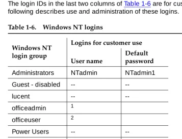
■ Customer access 1-42
■ Windows NT logins for the customer 1-43
■ DEFINITY logins for the customer 1-49
■ Comcodes for Release 2.0 1-53
2
Maintenance Procedures forDEFINITY ONE Compact Modular Cabinets 2-1
■ Preventive maintenance 2-1
■ Recovery from fatal errors 2-4
■ Resolving alarms 2-5
■ Reseating/replacing circuit packs 2-7
■ Replace the TN795 circuit pack 2-8
■ Replace the hard disk 2-9
■ Removing power 2-11
■ Restoring power 2-12
■ Setting neon voltage (ring ping) 2-13
■ Troubleshooting features 2-14
■ Install DS1 CPE loopback jack
(T1 only) 2-39
■ Multimedia call handling 2-52
■ TN760D tie trunk option settings 2-60
■ TN464E/F option settings 2-62
■ Troubleshooting multimedia call handling (MMCH) 2-63
3
Global Administration Subsystem Commands 3-1■ alarmorig 3-5
■ alarmstat 3-6
■ autobackup 3-6
■ cleargamalarm 3-7
■ backupparms 3-8
■ backupsource 3-9
■ d1backup 3-11
■ d1restore 3-13
■ d1stat 3-14
■ downloadboot 3-15
Contents
v
■ exit 3-17
■ fileversion 3-17
■ ftpserv 3-17
■ fwversion 3-18
■ gamalarmstat 3-19
■ identbackup 3-20
■ installconfig 3-21
■ lucent help 3-21
■ net user 3-21
■ oss 3-22
■ pcanywhere 3-23
■ post 3-23
■ productid 3-24
■ rasdrop 3-24
■ reboot 3-25
■ restartcause 3-25
■ schedbackup 3-26
■ serialnumber 3-27
■ setip 3-28
■ siteconfig 3-30
■ shutdown 3-30
■ start 3-33
■ swversion 3-34
■ terminate 3-35
■ versiondiff 3-36
4
Maintenance Commands for DEFINITY ONE 4-1■ System command structure 4-1
■ busyout access-endpoint 4-2
■ busyout adjunct-ip-link 4-4
■ busyout board 4-6
■ busyout cdr-link 4-7
■ busyout data-module 4-8
■ busyout link 4-10
■ busyout mis 4-11
Contents
vi
■ busyout pri-endpoint 4-13
■ busyout station 4-14
■ busyout tdm 4-15
■ busyout tone-clock 4-16
■ busyout trunk 4-17
■ cancel hardware-group 4-18
■ change circuit-packs 4-19
■ change synchronization 4-21
■ change system-parameters maintenance 4-22
■ clear audits 4-30
■ clear errors 4-30
■ clear isdnpri-testcall 4-31
■ clear mst 4-31
■ clear pkt 4-31
■ clear port 4-31
■ disable administered-connection 4-32
■ disable mst 4-32
■ disable suspend-alm-orig 4-32
■ disable synchronization-switch 4-33
■ disable test-number 4-33
■ display alarms 4-33
■ display capacity 4-38
■ display disabled-tests 4-48
■ display errors 4-49
■ display events 4-55
■ display initcauses 4-57
■ display port 4-59
■ display synchronization 4-60
■ display system-parameters maintenance 4-61
■ display time 4-69
■ enable administered-connection 4-70
■ enable mst 4-70
■ enable suspend-alm-orig 4-70
Contents
vii
■ enable test-number 4-72
■ list configuration 4-72
■ list config software-version 4-75
■ list disabled-mos 4-76
■ list history 4-77
■ list isdn-testcall 4-79
■ list marked-ports 4-80
■ list measurements 4-81
■ list suspend-alm-orig 4-84
■ list sys-link 4-85
■ list testcalls 4-86
■ mark port 4-90
■ monitor bcms 4-90
■ monitor health 4-95
■ monitor security-violations 4-98
■ monitor system 4-99
■ monitor traffic 4-105
■ monitor trunk 4-107
■ recycle carrier 4-108
■ release access-endpoint 4-109
■ release adjunct-ip-link 4-110
■ release board 4-112
■ release cdr-link 4-113
■ release data-module 4-114
■ release mis 4-115
■ release modem-pool 4-116
■ release port 4-117
■ release pri-endpoint 4-118
■ release station 4-119
■ release tdm 4-120
■ release tone-clock 4-121
■ release trunk 4-122
■ reset board 4-123
■ reset packet-interface 4-124
Contents
viii
■ reset system 4-125
■ reset tone-clock 4-126
■ resume hardware-group 4-128
■ save translation 4-129
■ set options 4-130
■ set signaling-group 4-135
■ set synchronization 4-135
■ set tdm 4-136
■ set tone-clock 4-136
■ status access-endpoint 4-137
■ status administered-connection 4-138
■ status asai/adjunct tcp/ip link 4-140
■ status attendant 4-142
■ status audits 4-143
■ status bri-port 4-151
■ status cdr-link 4-158
■ status cleared-alarm-notif 4-159
■ status conference 4-159
■ status data-module 4-195
■ status hardware-group 4-197
■ status health 4-199
■ status isdn-testcall 4-202
■ status link 4-204
■ status packet-interface 4-204
■ status periodic-scheduled 4-205
■ status pri-endpoint 4-206
■ status processor-channel 4-208
■ status remote-access 4-210
■ status signaling-group 4-211
■ status station 4-213
■ status synchronization 4-216
■ status sys-link 4-217
■ status system 4-219
Contents
ix
■ status tsc-administered 4-225
■ status tti 4-226
■ test access-endpoint 4-228
■ test alarms 4-230
■ test analog-testcall 4-235
■ test board 4-237
■ test cdr-link 4-240
■ test customer-alarm 4-241
■ test data-module 4-243
■ test ds1-loop 4-244
■ test eda-external-device-alrm 4-247
■ test environment 4-249
■ test hardware-group 4-251
■ test inads-link 4-256
■ test isdnpri-testcall 4-258
■ test led 4-260
■ test modem-pool 4-260
■ test packet-interface 4-261
■ test pkt 4-262
■ test port 4-264
■ test pri-endpoint 4-266
■ test pr-maintenance 4-268
■ test signaling-group 4-269
■ test station 4-271
■ test switch-control 4-273
■ test synchronization 4-274
■ test sys-link 4-276
■ test tdm 4-278
■ test tone-clock 4-280
■ test translation-store 4-281
■ test trunk 4-283
Contents
x
5
Maintenance Objects for DEFINITY ONE 5-1■ ABRI-PORT (ASAI ISDN-BRI Port) 5-2
■ ADJLK-IP (ASAI Adjunct IP Link) 5-2
■ ADM-CONN (administered connection) 5-13
■ ALARM-PT (ALARM port) 5-18
■ ANL-16-L (16-Port Neon Analog Line) 5-26
■ ANL-24-L (24-Port Analog Line) 5-44
■ ANL-BD (analog line circuit pack) 5-64
■ ANL-LINE (8-port analog line),
ANL-NE-L (8-port neon analog line) 5-65
■ AN-LN-PT (Analog Line Port) 5-88
■ ANN-BD (announcement circuit pack) 5-112
■ ANN-PT (announcement port) 5-133
■ ANNOUNCE (announce) 5-144
■ ASAI-BD (Multi-Application Platform Board) 5-148
■ ASAI-EPT 5-150
■ ASAI-PT 5-158
■ ASAI-RES/E-DIG-RES (TN800 reserve slot) 5-168
■ ATM-BCH (ATM B-channel trunk) 5-169
■ ATM-DCH (ATM D-channel port) 5-184
■ ATM-EI (Expansion Interface Circuit Pack) 5-187
■ ATM-INTF (TN2305/6) 5-239
■ ATM-NTWK (ATM Network Error) 5-243
■ ATM-SGRP (ATM signaling group) 5-251
■ ATM-TRK (circuit emulation service
circuit pack) 5-264
■ BRI-BD/LGATE-BD (ISDN-BRI Line Circuit Pack) 5-305
■ BRI-DAT (ISDN-BRI) 5-312
■ BRI-PORT (ISDN-BRI Port),
ABRI-PORT (ASAI ISDN-BRI Port) 5-312
■ BRI-SET, ASAI-ADJ, BRI-DAT 5-334
■ CABINET (Cabinet Sensors) 5-363
■ CDR-LNK (CDR Link) 5-371
■ CLAN-BD (Control LAN Circuit Pack) 5-378
■ CLSFY-BD (Call Classifier Circuit Pack) 5-394
Contents
xi
■ CO-BD (Central Office Trunk Circuit Pack) 5-401
■ CO-DS1 (DS1 CO Trunk) 5-402
■ CO-TRK (CO Trunk) 5-419
■ CONFIG (System Configuration) 5-445
■ CUST-ALM (Customer-Provided Alarming Device) 5-446
■ DATA-CHL (Data Channel) 5-449
■ DAT-LINE (Data Line) 5-466
■ DETR-BD (International Version) 5-474
■ DID-BD (Direct Inward Dial Trunk Circuit Pack) 5-474
■ DID-DS1 (DS1 DID Trunk) 5-475
■ DID-TRK (DID Trunk) 5-486
■ DIG-BD (Digital Line Circuit Pack) 5-501
■ DIG-LINE (Digital Line) 5-502
■ DIOD-DS1 (DS1 DIOD Trunk) 5-526
■ DIOD-TRK (DIOD Trunk), DIOD-BD
(DIOD Circuit Pack) 5-537
■ DIOD-TRK (DIOD Trunk) 5-537
■ DLY-MTCE (MO-DAILY) 5-548
■ DS1-BD (DS1 Interface Circuit Pack) 5-548
■ DT-LN-BD (Data Line Circuit Pack) 5-624
■ DTMR-PT [Dual Tone Multifrequency Port (TTR)] 5-624
■ E-DIG-BD (Multi Application Platform Board) 5-629
■ E-DIG-STA (Emulated Digital Line) 5-631
■ EMG-XFER 5-641
■ ERR-LOG (Error Log) 5-644
■ ETH-PT (Control LAN Ethernet) 5-645
■ ETR-PT (Enhanced Tone Receiver Port) 5-655
■ EXT-DEV ADMIN? N (External Device Alarm) 5-660
■ EXT-DEV ADMIN? Y (External Device Alarm) 5-663
■ GPTD-PT [General Purpose Tone
Detector Port (CPTR)] 5-667
■ H323-SGRP (H.323 Signaling Group) 5-668
■ HYB-BD (Hybrid Line Circuit Pack) 5-673
■ HYB-LINE (Hybrid Line) 5-674
Contents
xii
■ ISDN-PLK (ISDN-PRI Signaling Link Port) 5-699
■ ISDN-SGR (ISDN-PRI Signaling Group) 5-705
■ ISDN-TRK (DS1 ISDN Trunk) 5-722
■ LGATE-AJ 5-749
■ LGATE-BD 5-749
■ LGATE-PT 5-749
■ LOG-SVN (Login Security Violation) 5-749
■ MAPD-BD (MAPD Interface Circuit Pack TN802) 5-752
■ MEDPROPT (TN802 MED PRO DSP PORT) 5-782
■ MEM-BD (Memory) 5-788
■ MEMORY 5-794
■ MET-BD (MET Line Circuit Pack) 5-794
■ MET-LINE (MET Line) 5-795
■ MIS (Management Information System) 5-815
■ MMI-BD 5-818
■ MMI-LEV (Multimedia Interface Resource Level) 5-828
■ MMI-PT 5-831
■ MMI-SYNC 5-836
■ MODEM-BD (Modem Pool Circuit Pack) 5-838
■ MODEM-PT (Modem Pool Port) 5-838
■ M/T-ANL (Maintenance/Test Analog Port) 5-854
■ M/T-BD (Maintenance/Test Circuit Pack) 5-864
■ M/T-DIG (Maintenance/Test Digital
Port) [G3iV1-1.286, G3iV2-386] 5-865
■ M/T-PKT (Maintenance/Test Packet Bus Port) 5-877
■ OPS-LINE (DS1 OPS Line) 5-882
■ PDMODULE, TDMODULE (Data Module) 5-894
■ PE-BCHL (PRI Endpoint Port) 5-913
■ PI-LINK (Processor Interface Link) 5-934
■ PKT-BUS (Packet Bus) 5-950
■ PKT-INT (Packet Interface) 5-958
■ PMS-PRNT/JNL-PRNT (PMS Printer Link) 5-974
■ PPP-PT (Control LAN Packet/Port) 5-980
Contents
xiii
■ PR-AL-BD (Processor Alarm Board) 5-997
■ PR-MAINT (Maintenance Processor) 5-1000
■ PROCR (Processor Circuit Pack) 5-1008
■ PR-SSP (Processor Board - Scalable
Speech Processor) 5-1015
■ PR-TN-BD (TN795
Processor/Tone-Clock) 5-1023
■ PROC-SAN (Process Sanity Audits) 5-1035
■ RING-GEN (Analog Ring Generator) 5-1036
■ S-SYN-BD (Speech Synthesis Circuit Pack) 5-1040
■ S-SYN-PT (Speech Synthesis Port) 5-1041
■ SW-CTL (Switch Control) 5-1054
■ SYNC (Synchronization) 5-1063
■ SYS-LINK (System Links) 5-1070
■ SYSTEM (System) 5-1075
■ TBRI-BD (TN2185
ISDN Trunk-Side BRI) 5-1077
■ TBRI-PT (TN2185
ISDN Trunk-Side BRI Port) 5-1085
■ TBRI-TRK (TN2185
ISDN Trunk-Side BRI) 5-1105
■ TDM-BUS (TDM Bus) 5-1116
■ TDM-CLK (TDM Bus Clock) 5-1132
■ TDMODULE (Trunk Data Module) 5-1142
■ TIE-BD (Tie Trunk Circuit Pack) 5-1143
■ TIE-DS1 (DS1 Tie Trunk) 5-1144
■ TIE-TRK (Tie Trunk) 5-1161
■ TONE-BD (Tone-Clock Circuit Pack) 5-1184
■ TONE-PT (Tone Generator) 5-1204
■ TRANS-STO (Translation Storage) 5-1214
■ TSC-ADM (Administered Temporary
Signaling Connections) 5-1217
■ TTR-LEV (TTR Level) 5-1223
■ UDS1-BD (UDS1 Interface Circuit Pack) 5-1227
■ VC-BD 5-1315
Contents
xiv
■ VC-LEV (Voice Conditioner
DSP Port Level) 5-1328
■ VC-SUMPT 5-1331
■ WAE-PORT (Wideband Access Endpoint Port) 5-1336
■ XXX-BD (Common Port Circuit Pack) 5-1343
6
DEFINITY ONE NT Log Events and Alarms 6-1■ Introduction 6-1
■ Alarms for DEFINITY ONE Co-Resident Services 6-3
A
Summary of DEFINITY ONE Commands A-1■ LAC GAS Commands A-11
B
Access Security Gateway B-1■ Using the ASG Mobile B-1
About This Document
xv Purpose
About This Document
Purpose
This book contains the information needed to monitor, test, and maintain DEFINITY ONE
™
Communications System and covers many of the faults and troubles that can occur in the system. Most maintenance requirements are simple procedures due to the modular, self-testing nature of the system.Simple, traditional troubleshooting methods are sometimes sufficient to locate and clear faults. The traditional methods include terminal substitution, visual inspections, continuity checks, and clarification of operating procedures with end users.
DEFINITY ONE is a high-functionality communications system for customers in the 25-40 line size or smaller with growth potential to 168 stations. This offer provides DEFINITY® software, INTUITY® AUDIX® messaging, and DEFINITY Site Administration (DSA) on a single hardware platform
Intended audience
The information in this book is intended for use by:
■ A maintenance technician dispatched to a DEFINITY ONE site in response
to a trouble alarm or a user trouble report
■ A maintenance technician located at a remote maintenance facility ■ The customer’s assigned maintenance technician. The technician is
About This Document
xvi Organization
Each DEFINITY ONE System has a user-designated System Manager who is responsible for system administration and with whom the maintenance technician should work closely.
This book is not intended to solve all levels of troubles. It is limited to troubles that can be solved by using the Alarm Log, Error Log, trouble-clearing procedures, maintenance tests, and traditional troubleshooting methods. If the trouble still has not been resolved, it is the responsibility of the maintenance technician to escalate the problem to a higher level of technical support. Escalation should conform to the procedures in the Technical and Administration Escalation Plan.
Organization
Chapter 1, ‘‘Maintenance Concepts for DEFINITY ONE’’
Describes what’s new in DEFINITY ONE, the system design and maintenance strategy, reset and reboot processes, LED sequences, allowable circuit packs, and component comcodes.
Chapter 2, ‘‘Maintenance Procedures for DEFINITY ONE Compact Modular Cabinets’’
Describes the various maintenance procedures: powering up and down,
connecting to DEFINITY ONE, getting access to the system software, replacing
components, routine maintenance, troubleshooting advice.
Chapter 3, ‘‘Global Administration Subsystem Commands’’
Describes the commands available via the command line interface.
Chapter 4, ‘‘Maintenance Commands for DEFINITY ONE’’
Explains how to use the maintenance commands including specific command syntax, typical forms, and display output.
Chapter 5, ‘‘Maintenance Objects for DEFINITY ONE’’
Contains specific troubleshooting and repair instructions for every maintenance
component in the system. This chapter also contains repair procedures for
system-alarmed and user-reported troubles. For each Maintenance Object (MO), a table lists the alarm level, hardware error
About This Document
xvii Conventions used in this book
Conventions used in this book
Circuit pack codes (such as TN763D) are shown with the minimum acceptable alphabetic suffix (for example, the “D” in the code TN763D).
Generally, an alphabetic suffix greater than that shown is also acceptable. However, not every vintage of either the minimum suffix or a higher suffix code is necessarily acceptable.
NOTE:
Refer to Technical Monthly: Reference Guide for Circuit Pack Vintages and Change Notices for current information about usable vintages of specific circuit pack codes (including the suffix).
The following conventions describe the systems referred to in this document.
■ System is a general term encompassing Release 2.0 and includes
references to DEFINITY ONE.
■ Information is applicable for Release 2.0 unless otherwise specified ■ DEFINITY ONE Communications System is abbreviated as DEFINITY
ONE.
Physical dimensions in this book are in inches followed by metric centimeters (cm) in parentheses. Wire gauge measurements are in American Wire Gauge (AWG) followed by the cross-sectional area in squared millimeters (mm2) in parentheses.
Chapter 6, ‘‘DEFINITY ONE NT Log Events and Alarms’’
Describes alarms for each software
subsystem, listed by alarm number. Advice for resolving alarms is also provided.
Appendix A, ‘‘Summary of DEFINITY ONE Commands’’
Provides brief descriptions for the commands you encounter in using the DEFINITY ONE system.
About This Document
xviii Typographic conventions
Typographic conventions
This document uses the following typographic conventions:
■ Information you type at the management terminal is shown in the following
typeface: list system-parameters maintenance.
■ Information displayed on the management terminal screen is shown in the
following typeface: login.
■ Keyboard keys are shown in the following typeface: Enter.
The following conventions describe the systems referred to in this document.
■ Circuit pack codes (such as TN763D) are shown with the minimum
acceptable alphabetic suffix (like the “D” in the code TN763D).
■ An alphabetic suffix greater than that shown is also acceptable. However,
not every vintage of either the minimum suffix or a higher suffix code is necessarily acceptable.
NOTE:
Refer to Technical Monthly: Reference Guide for Circuit Pack Vintages and Change Notices for current information about usable vintages of specific circuit pack codes (including the suffix).
■ The word system is a general term encompassing Release 2.0 and
includes references to DEFINITY ONE.
■ Information in this book is applicable for Release 2.0 unless otherwise
specified
■ DEFINITY ONE Communications System is abbreviated as DEFINITY
ONE.
■ Physical dimensions in this book are in inches followed by metric
centimeters (cm) in parentheses. Wire gauge measurements are in AWG followed by the cross-sectional area in squared millimeters (mm2) in parentheses.
About This Document
xix Admonishments
Admonishments
Admonishments used in this book have the following meanings:
!
CAUTION:
This sign is used to indicate possible harm to software, possible loss of data, or possible service interruptions.
!
WARNING:
This sign is used where there is possible harm to hardware or equipment.
!
DANGER:
This sign is used to indicate possible harm or injury to people.
Safety precautions
When performing maintenance or translation procedures on the system, users must observe certain precautions. Observe all caution, warning, and danger admonishments to prevent loss of service, possible equipment damage, and possible personal injury. In addition, the following precautions regarding electromagnetic interference (EMI) and static electricity must be observed:
Electromagnetic interference
This equipment generates, uses, and can radiate radio frequency energy. Electromagnetic fields radiating from the switch may cause noise in the
customer’s equipment. If the equipment is not installed and used in accordance with the instruction book, radio interference may result.
!
WARNING:
About This Document
xx Security issues
Static electricity
To prevent or reduce electrostatic discharge (ESD), maintenance personnel must always attach wrist grounding straps before working on switch components or handling circuit packs.
!
CAUTION:
Electrostatic discharge can damage or destroy circuit packs containing integrated circuits (ICs).
The ESD wrist strap, cable assembly, and spare fuses are packed in a plastic bag and placed in the top of the system cabinet. Use the ESD wrist strap when troubleshooting, performing maintenance, or handling any circuit packs associated with the system.
Security issues
To ensure the greatest security possible for customers, Lucent Technologies offers services that can reduce toll-fraud liabilities. Contact your Lucent Technologies representative for more security information.
Login security is an attribute of the DEFINITY ONE software. Existing passwords expire 24 hours after installation.
For Software Copy Protection information, see Chapter 10, “Security and Copy Protection” in the DEFINITY ONE Communications System Release 2.0
Installation and Upgrades (555-233-109).
NOTE:
About This Document
xxi Standards compliance
Standards compliance
The equipment presented in this document complies with the following (as appropriate):
■ ITU-T (Formerly CCITT) ■ ECMA
■ ETSI ■ IPNS
■ DPNSS
■ National ISDN-1 ■ National ISDN-2 ■ ISO-9000 ■ ANSI
■ FCC Part 15 and Part 68 ■ EN55022
■ EN50081 ■ EN50082 ■ CISPR22
■ Australia AS3548 (AS/NZ3548) ■ Australia AS3260
■ IEC 825 ■ IEC950 ■ UL 1459 ■ UL1950
About This Document
xxii Electromagnetic compatibility standards
Electromagnetic compatibility
standards
This product complies with and conforms to the following:
■ Limits and Methods of Measurements of Radio Interference
Characteristics of Information Technology Equipment, EN55022 (CISPR22), 1993
■ EN50082-1, European Generic Immunity Standard ■ FCC Parts 15 and 68
■ Australia AS3548 NOTE:
The system conforms to Class A (industrial) equipment; voice terminals meet Class B requirements.
■ Electrostatic Discharge (ESD) IEC 1000-4-2 ■ Radiated radio frequency field IEC 1000-4-3 ■ Electrical Fast Transient IEC 1000-4-4 ■ Lightning effects IEC 1000-4-5
■ Conducted radio frequency IEC 1000-4-6 ■ Mains frequency magnetic field IEC 1000-4-8 ■ Low-frequency mains disturbance
The system conforms to the following:
■ Electromagnetic compatibility General Immunity Standard, part 1;
residential, commercial, light industry, EN50082-1, CENELEC, 1991
■ Issue 1 (1984) and Issue 2 (1992), Electrostatic-discharge immunity
requirements (EN55024, Part 2) IEC 1000-4-2
About This Document
xxiii Trademarks and service marks
European Union standards
Lucent Technologies Business Communications Systems declares that the DEFINITY equipment specified in this document bearing the “CE” mark conforms to the European Union Electromagnetic Compatibility Directives.
The “CE” (Conformité Europeénne) mark indicates conformance to the:
■ European Union Electromagnetic Compatibility Directive (89/336/EEC) ■ Low Voltage Directive (73/23/EEC)
■ Telecommunication Terminal Equipment (TTE) Directive (91/263/EEC) ■ i-CTR3 Basic Rate Interface (BRI) and i-CTR4 Primary Rate Interface (PRI)
as applicable.
The “CE” mark is applied to the following DEFINITY ONE product:
■ AC-powered Compact Single-Carrier Cabinet (CSCC) with 25-Hz ring
generator
Trademarks and service marks
The following are trademarks or registered trademarks of Lucent Technologies:
■ 5ESS
™,
4ESS™
■ Ascend®(A wholly owned subsidiary of Lucent Technologies) ■ AUDIX®
■ Callvisor® ■ Callmaster® ■ CentreVu™ ■ CONVERSANT® ■ DEFINITY® ■ DEFINITY ONE™ ■ DIMENSION® ■ MERLIN® ■ VOICE POWER®
The following are trademarks or registered trademarks of AT&T:
■ ACCUNET® ■ DATAPHONE®
■ MEGACOM®
About This Document
xxiv Related documents
The following are trademarks or registered trademarks of other companies:
■ Audichron® (registered trademark of the Audichron Company) ■ MS-DOS® (registered trademark of the Microsoft Corporation) ■ MicroChannel® (registered trademark of IBM Systems)
■ MULTIQUEST® (registered trademark of Telecommunications Service) ■ PagePac® (trademark of the Dracon Division of the Harris Corporation) ■ UNIX®
(
trademark of the Novell Corporation)■ Windows NT® (registered trademark of the Microsoft Corporation) ■ Internet Explorer® is a registered trademark of Microsoft Corporation ■ Netscape® is a registered trademark of Netscape Communications
Corporation
Related documents
■ BCS Products Security Handbook (555-025-600)
■ DEFINITY Enterprise Communications Server Release 8.2 Installation for
Adjuncts and Peripherals (555-230-125)
■ DEFINITY Enterprise Communications Server Release 8.2 Administrator’s
Guide (555-230-506)
■ DEFINITY Enterprise Communications System R 8.2 Administration for
Network Connectivity (555-233-501)
■ DEFINITY Enterprise Communications Server Release 8.2 System
Description Pocket Reference (555-230-211)
■ DEFINITY Communications System and System 75 and System 85
Terminals and Adjuncts (555-015-201)
■ DEFINITY ONE Communications System Release 2.0 Overview
(555-233-001)
■ DEFINITY ONE Communications System Release 2.0 Installation and
About This Document
xxv Federal Communications Commission statement
Federal Communications Commission
statement
Part 68: statement
Part 68: Answer-Supervision Signaling. Allowing this equipment to be operated in a manner that does not provide proper answer-supervision signaling is in violation of Part 68 rules. This equipment returns answer-supervision signals to the public-switched network when:
■ Answered by the called station ■ Answered by an attendant
■ Routed to a recorded announcement or music in queue that can be
administered by the CPE user
This equipment returns answer-supervision signals on all DID calls forwarded back to the public-switched telephone network, with these exceptions:
■ A call is unanswered ■ A busy tone is received ■ A reorder tone is received
This equipment is capable of providing users access to interstate providers of operator services through the use of access codes. Modification of this
equipment by call aggregators to block access dialing codes is a violation of the Telephone Operator Consumers Act of 1990.
This equipment complies with Part 68 of the FCC Rules. On the rear of this equipment is a label that contains, among other information, the FCC registration number and ringer equivalence number (REN) for this equipment. If requested, this information must be provided to the telephone company. The REN is used to determine the number of devices connected to the telephone line. Excessive RENs on the telephone line may result in devices not ringing in response to an incoming call. In most, but not all areas, the sum of RENs should not exceed 5.0. To be certain of the number of devices that can be connected to a line, as determined by the total RENs, contact the local telephone company.
NOTE:
About This Document
xxvi Federal Communications Commission statement
Means of Connection (U.S.)
Connection of this equipment to the telephone network is shown in the following table.
If the terminal equipment (DEFINITY system) causes harm to the telephone network, the telephone company may notify you in advance that temporary discontinuance of service is required. But if advance notice is not practical, the telephone company may notify the customer as soon as possible thereafter. Also, you will be advised of your right to file a complaint with the FCC if you believe it is necessary.
The telephone company may make changes in its facilities, equipment,
operations, or procedures that could affect the operation of the equipment. If this happens, the telephone company will provide advance notice so you can make the necessary modifications to maintain uninterrupted service.
If trouble is experienced with this equipment or for repair or warranty information, please contact the Technical Service Center at 1-800-248-1234. If the equipment causes harm to the telephone network, the telephone company may request that you disconnect the equipment until the problem is resolved.
It is recommended that repairs be performed by Lucent Technologies-certified technicians.
The equipment cannot be used on public coin-phone service. Connection to party-line service is subject to state tariffs. Contact the state public utility commission, public service commission, or corporation commission for information.
This equipment is hearing aid compatible if a telephone receiver is used.
Manufacturer’s Port
Identifier FIC Code
SOC/REN/
A.S. Code Network Jacks
Off- /On-Premises Station OL13C 9.0F RJ2GX,
RJ21X, RJ11C
DID Trunk 02RV2-T 0.0B RJ2GX, RJ21X
CO Trunk (ground start) 02GS2 0.3A RJ21X
CO Trunk (loop start) 02LS2 0.3A RJ21X
Tie Trunk TL31M 9.0F RJ2GX
1.544 Digital Interface 04DU9-B, C 6.0P RJ48C, RJ48M
1.544 Digital Interface 04DU9-BN, KN
6.0P RJ48C, RJ48M
About This Document
xxvii How to order documentation
How to order documentation
A complete list of DEFINITY ONE, DEFINITY, and AUDIX books is available in the
Business Communications System Publications Catalog, 555-000-010.
You can order this document and any other documentation directly from the Lucent Technologies Business Communications System Publications Fulfillment Center at 1-317-322-6791 or toll free at 1-800-457-1235.
How to comment on this book
Lucent Technologies welcomes your feedback. Please fill out the reader comment card at the end of this book and return it. Your comments are of great value and help us to improve our documentation.
About This Document
xxviii Where to call for technical support
Where to call for technical support
Telephone number
Streamlined Implementation (for missing equipment) 1-800-772-5409
USA/Canada Technical Service Center 1-800-248-1234
Technical Service Center (INADS Database Administration) 1-800-248-1111
Asia/Pacific Regional Support Center 65-872-8686
Western Europe/South Africa/Middle East 441-252-774-800
Business Communications Europe 441-252-391-789
Eastern/Central Europe 361-345-4334
ITAC 1-303-804-3777
Latin/Central America & Caribbean 1-303-804-3778
DEFINITY Helpline 1-800-225-7585
Lucent Technologies Toll Fraud Intervention 1-800-643-2353
Lucent Technologies Technical Care Center 1-800-242-2121
Lucent Technologies Corporate Security 1-800-822-9009
DEFINITY Site Administration (DSA) Domestic 1-800-242-2121
DEFINITY Site Administration (DSA) International Call Local Dealer
Maintenance Concepts for DEFINITY ONE
1-1 What’s New in DEFINITY ONE Release 2.0
1
1
Maintenance Concepts for
DEFINITY ONE
The maintenance subsystem is a part of the software that initializes and maintains the system. The software continuously monitors system health and keeps a record of errors detected in the system. The maintenance subsystem also provides a user interface for on-demand testing. This chapter provides a brief description of the Release 2.0 maintenance strategy and background information on the system’s overall functions.
What’s New in DEFINITY ONE
Release 2.0
■ ‘‘TN795 processor circuit pack’’ ■ ‘‘Virtual boards and devices’’ ■ ‘‘Windows NT platform’’
■ ‘‘pcAnywhere third-party software’’ on page 1-3 ■ ‘‘GUI operation’’
■ ‘‘New backup procedures’’ ■ ‘‘DEFINITY ONE™ design’’
■ “Connectivity and Access to DEFINITY ONE” see ‘‘Accessing DEFINITY
ONE™ for maintenance’’ on page 1-26
■ ‘‘DEFINITY LAN Gateway maintenance’’ on page 1-19 ■ ‘‘DLG release-from-busyout results’’ on page 1-22
Maintenance Concepts for DEFINITY ONE
1-2 What’s New in DEFINITY ONE Release 2.0
1
TN795 Processor circuit pack
The TN795 processor provides:
■ An on-board Pentium processor chip that runs Windows NT ■ A Motorola processor running application firmware
■ An NT-to-firmware interface ■ A tone clock
■ 1A12 alarm board
■ 1A11 and 1A13 virtual boards ■ A “virtual” AUDIX board
See ‘‘DEFINITY ONE™ design’’ on page 1-5 and the DEFINITY ONE™ Communications System Release 2.0 Overview (555-233-001), for more information regarding the TN795.
Virtual boards and devices
The TN795 processor circuit pack includes functions, (such as the tone clock) that had previously resided on separate circuit packs. Commands, tests, and maintenance objects that were valid for the separate circuit packs are still available.
A virtual AUDIX board (PR-SSP) resides in slot 1A12. The hardware for this board is located on the TN795 but the AUDIX ports on the board are administered as if they were physical ports on the virtual board. Virtual boards, designated1A11 and 1A13, reside in slots 11 and 13. The 1A11 board is used by DEFINITY to provide External Device Alarm contacts to indicate presence of any
non-DEFINITY alarms. See ‘‘PR-AL-BD (Processor Alarm Board)’’ on page 5-997. The 1A13 is a TN795 Processor Board.
Windows NT platform
Maintenance Concepts for DEFINITY ONE
1-3 What’s New in DEFINITY ONE Release 2.0
1
The following applications are installed or available on the DEFINITY ONE system:
pcAnywhere third-party software
If you have pcAnywhere application software installed on your laptop, on a PC, or the customer network, you can use it to access the DEFINITY ONE system just as if you had a monitor, keyboard, and mouse directly connected to the DEFINITY ONE cabinet location.
You can also get access to the DEFINITY ONE system using Telnet sessions. (See ‘‘Recovery from fatal errors’’ on page 2-4 for more information.)
These connections can be over a PCMCIA Network Connection, a RAS Modem Connection, or a customer LAN Connection.
GUI operation
DEFINITY ONE uses DEFINITY Site Administration (DSA) which has a graphical user interface (GUI) for all functions. See Chapter 2, “Connectivity and Access to DEFINITY ONE” in DEFINITY ONE™ Communications System Release 2.0 Installation and Upgrades (555-233-109).
New backup procedures
Since the DEFINITY ONE system combines DEFINITY, AUDIX and Windows NT on one platform, there is a new procedure to back up user information and translations.
Backup is performed in one of two ways:
■ Using the web browser
■ Using the UNIX-like bash shell, accessed via a Telnet session ■ DEFINITY ONE, with a series of global administration system (GAS)
commands (see Chapter 3, ‘‘Global Administration Subsystem Commands’’ for a list of GAS commands).
NOTE:
If a backup or restore operation is in progress, no other backup or restore command can be executed until the first one has finished.
■ DEFINITY Provides DEFINITY call processing features
■ AUDIX Provides voice mail.
■ pcAnywhere Must also be installed on the laptop or other
network PC. Alternatively use the web based pcAnywhere Java client.
Maintenance Concepts for DEFINITY ONE
1-4 What’s New in DEFINITY ONE Release 2.0
1
How backup works
The DEFINITY ONE system performs a backup by copying the files to be stored into a destination directory.
■ All files currently in the directory are removed prior to backup. ■ An identification file (ident file) is created for each backup, listing:
— Version of backup program
— Date and time the backup started
— Date and time the backup completed
— Code indicating successful completion or reason of failure
— Indication of full or partial backup
■ A global alarm is raised if an error occurs during a backup operation. ■ Checksum verification is performed on all translation files.
!
WARNING:
Saving translations through the hard drive does not constitute a system backup. The data can still be lost.
Maintenance Concepts for DEFINITY ONE
1-5 What’s New in DEFINITY ONE Release 2.0
1
Where to save translations and system user data
Once the data has been placed on the hard drive, it should also be saved on a backup drive. Data can be backed up to:
DEFINITY ONE™ design
This section describes major design highlights for DEFINITY ONE. For further information, see the DEFINITY ONE Communications System Release 2.0 Overview (555-233-001).
Three slots are reserved (2 slots for the processor and one slot for the tone detector circuit pack).
■ PCMCIA Flash
Disk
The flash disk is a nonvolatile storage device installed in a PCMCIA slot on the TN795.
A system backup to flash card will save only
— Windows system registry
— DEFINITY translations
— AUDIX translations
— Header information for AUDIX messages
!
WARNING:
Messages should not be saved on the flash disk, because there is limited space. If you want to save messages, you must back up the files to another device on the customer network.
■ Network
device
You can back up all applications and messages to any network device that has enough storage, and is accessible across the network by DEFINITY ONE. Such devices include:
— Network disk drives
— Servers
— Tape drives
Maintenance Concepts for DEFINITY ONE
1-6 What’s New in DEFINITY ONE Release 2.0
1
Compact modular cabinet
The DEFINITY ONE 10-slot Compact Modular Cabinet (CMC) includes:
■ Slots for circuit packs ■ Power supply
Slots
■ Two shelves of 5 slots each
■ The slots are numbered 1-5 (lower shelf), and 6-10 (upper shelf). NOTE:
The TN795 Processor circuit pack must be installed in slot 2 (due to width, slot 1 is unavailable).
■ See Figure1-1 on page1-8.
AC power supply unit (650A)
■ Multiple DC outputs: ± 5.1 VDC, -48 VDC, +8-14 VDC (fan speed control),
and -150 to -115 VDC (Neon bus)
■ Three switch-selectable AC ring outputs: 85 VAC @ 20 Hz (North
America), 72 VAC @ 25 Hz (international), and two 28 VAC @ 50 Hz (France)
■ For LED indicators and interpretation, see ‘‘Power supply LEDs’’ on page
1-41.
UPS
Use of an optional uninterruptable power supply (UPS) between the AC power source and the switch is recommended to maintain service without interruptions.
■ There is no battery backup available for the DEFINITY ONE switch. ■ If power is interrupted for more than 50 milliseconds, all calls are dropped
and dynamic memory is lost.
■ An external alarm is reserved for the UPS on the TN795 processor circuit
pack.
— If power is interrupted for more than one minute, a major alarm is raised.
Maintenance Concepts for DEFINITY ONE
1-7 What’s New in DEFINITY ONE Release 2.0
1
TN795 processor circuit pack
The TN795 Processor circuit pack is the heart of DEFINITY ONE. It uses Microsoft Windows NT as its operating system, allowing for graphical user interaction, network connections, standard applications, and coresidency and multitasking of applications. It is always found in slot 2 of the carrier (See Figure1-1 on page1-8).
The TN795 features include:
■ Dual processor complex consisting of an Intel Pentium and Motorola
processors
■ 16 Mbytes of FLASH PROM for software text
■ 128 Mbytes of DRAM for translations and other data. ■ RS232 port for the external modem
The DEFINITY ONE uses an external modem for alarm reporting to INADS and remote access. Approved modems include:
— U. S. Robotics Model 839 Sportster 33.6 Fax Modem (shipped with the DEFINITY ONE system)
This modem has a slightly different initialization string from other modems used with other DEFINITY products. Modem
administration is accomplished using Windows NT.
■ Connectors for local devices (keyboard, mouse, and monitor) ■ An interface for LAN connections
Features unique to the TN795 processor
■ The following LEDs are not provided on the TN795:
— WARNING LED (amber)
If there is a warning, consult the alarm log with the display alarms command. More details on the processor LEDs can be found in the
‘‘TN795 processor circuit pack LEDs’’ on page 1-34.
— ACK LED (green)
■ Processor and memory tests are no longer supported. Use the test board
Maintenance Concepts for DEFINITY ONE
1-8 What’s New in DEFINITY ONE Release 2.0
1
Reliability options
The DEFINITY ONE system does not support either high- or critical-reliability duplication or expansion options.
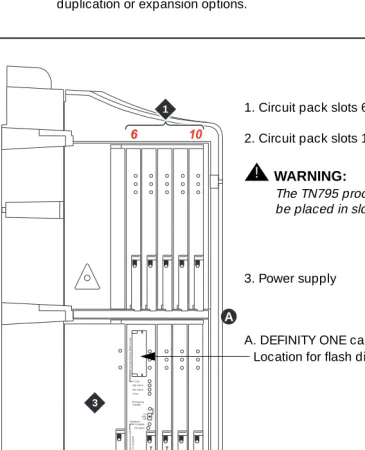
Figure 1-1. Compact Modular Cabinet (CMC) slot configuration scdmlft2 KLC 042699
5 10
1 2 3 4 6 Do No t Re mo ve W hen I n U s e Do No t Re mo ve Boar d U n til Shut do wn i s Co mp le te Emergency Transfer On AutoOff In Use Maj Alarm Min Alarm Clock Complete Shutdown Off switch 1 2 3 T N 7 9 5 T N 7 4 4 D A
1. Circuit pack slots 6 through 10
2. Circuit pack slots 1 through 5
!
WARNING:
The TN795 processor circuit pack must be placed in slot 2 (shown)
3. Power supply
Maintenance Concepts for DEFINITY ONE
1-9 Circuit packs
1
Circuit packs
All circuit pack slots in the Compact Modular Cabinet (CMC) are “universal slots.” That is, any slot can contain any type of circuit pack (port, control, or service), hence the absence of the purple and white slot coding found on other DEFINITY products. The only requirements for slot allocation are:
■ Service circuit packs listed in Table 1-1 are the only packs allowed in the
CMC. These “universal” service packs can be located in any slot numbered 3-10.
■ A TN744D Call Classifier/Tone Detector circuit pack is required in
DEFINITY ONE Release 2.0. This circuit pack can be installed into any slot, although slot 3 is preferred.
!
WARNING:
The TN795 Processor circuit pack must be located slot 2. Figure1-1 on
page1-8 also shows the PCMCIA disk drive location
Allowable and non-allowable circuit packs for
CMC
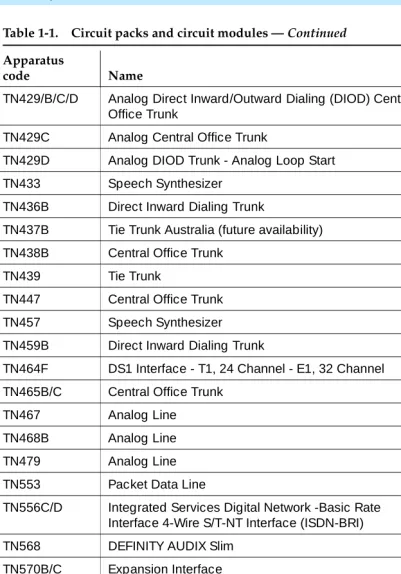
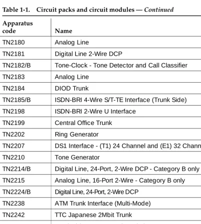
Table 1-1 lists the circuit packs allowable with DEFINITY ONE Release 2.0
Table 1-1. Circuit packs and circuit modules
Apparatus
code Name Allowable
650A AC Power Unit Yes
982LS Current Limiter No
CFY1B Current Limiter No
CPP1 Memory Expansion No
ED-1E546 (TN2208) (TN2170)
CallVisor Adjunct-Switch Application Interface (ASAI) over the DEFINITY (LAN) Gateway R1
No
J58890M-1 (TN801)
CallVisor ASAI/Call Visor PC/LAN over the DEFINITY LAN Gateway Release 2.0
No
NAA1 Fiber Optic Cable Adapter Circuit Pack Yes
TN417 Auxiliary Trunk Yes
TN419B Tone-Clock No
TN420B/C Tone Detector No
Maintenance Concepts for DEFINITY ONE
1-10 Circuit packs
1
TN429/B/C/D Analog Direct Inward/Outward Dialing (DIOD) Central Office Trunk
Yes
TN429C Analog Central Office Trunk Yes
TN429D Analog DIOD Trunk - Analog Loop Start Yes
TN433 Speech Synthesizer Yes
TN436B Direct Inward Dialing Trunk Yes
TN437B Tie Trunk Australia (future availability) Yes
TN438B Central Office Trunk Yes
TN439 Tie Trunk Yes
TN447 Central Office Trunk Yes
TN457 Speech Synthesizer Yes
TN459B Direct Inward Dialing Trunk Yes
TN464F DS1 Interface - T1, 24 Channel - E1, 32 Channel Yes
TN465B/C Central Office Trunk Yes
TN467 Analog Line Yes
TN468B Analog Line Yes
TN479 Analog Line Yes
TN553 Packet Data Line Yes
TN556C/D Integrated Services Digital Network -Basic Rate Interface 4-Wire S/T-NT Interface (ISDN-BRI)
Yes
TN568 DEFINITY AUDIX Slim No
TN570B/C Expansion Interface No
TN572 Switch Node Clock No
TN573B Switch Node Interface No
TN574 DS1 Converter - T1, 24 Channel No
TN577 Packet Gateway No
TN722B DS1 Tie Trunk Yes
TN725B Speech Synthesizer Yes
TN726B Data Line Yes
Table 1-1. Circuit packs and circuit modules — Continued
Apparatus
code Name Allowable
Maintenance Concepts for DEFINITY ONE
1-11 Circuit packs
1
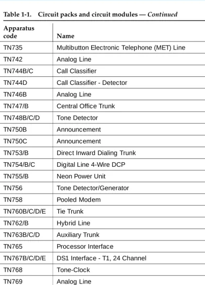
TN735 Multibutton Electronic Telephone (MET) Line Yes
TN742 Analog Line Yes
TN744B/C Call Classifier No
TN744D Call Classifier - Detector Yes
TN746B Analog Line Yes
TN747/B Central Office Trunk Yes
TN748B/C/D Tone Detector No
TN750B Announcement No
TN750C Announcement Yes
TN753/B Direct Inward Dialing Trunk Yes
TN754/B/C Digital Line 4-Wire DCP Yes
TN755/B Neon Power Unit No
TN756 Tone Detector/Generator No
TN758 Pooled Modem Yes
TN760B/C/D/E Tie Trunk Yes
TN762/B Hybrid Line Yes
TN763B/C/D Auxiliary Trunk Yes
TN765 Processor Interface No
TN767B/C/D/E DS1 Interface - T1, 24 Channel Yes
TN768 Tone-Clock No
TN769 Analog Line Yes
TN771/D Maintenance/Test No
TN772 Duplication Interface No
TN775/B/C Maintenance No
TN776 Expansion Interface No
TN777B Network Control No
TN778 Packet Control No
TN780 Tone-Clock No
Table 1-1. Circuit packs and circuit modules — Continued
Apparatus
code Name Allowable
Maintenance Concepts for DEFINITY ONE
1-12 Circuit packs
1
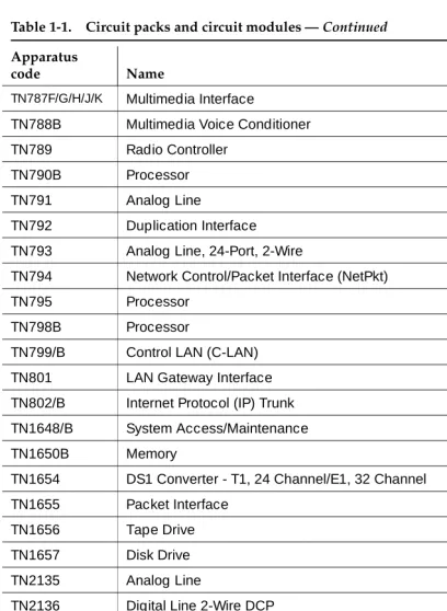
TN787F/G/H/J/K Multimedia Interface No
TN788B Multimedia Voice Conditioner No
TN789 Radio Controller Yes
TN790B Processor No
TN791 Analog Line Yes
TN792 Duplication Interface No
TN793 Analog Line, 24-Port, 2-Wire Yes
TN794 Network Control/Packet Interface (NetPkt) No
TN795 Processor Yes
TN798B Processor No
TN799/B Control LAN (C-LAN) Yes
TN801 LAN Gateway Interface No
TN802/B Internet Protocol (IP) Trunk Yes
TN1648/B System Access/Maintenance No
TN1650B Memory No
TN1654 DS1 Converter - T1, 24 Channel/E1, 32 Channel No
TN1655 Packet Interface No
TN1656 Tape Drive No
TN1657 Disk Drive No
TN2135 Analog Line Yes
TN2136 Digital Line 2-Wire DCP Yes
TN2138 Central Office Trunk Yes
TN2139 Direct Inward Dialing Trunk Yes
TN2140B Tie Trunk - Hungary, Italy Yes
TN2144 Analog Line Yes
TN2146 Direct Inward Dialing Trunk Yes
TN2147C Central Office Trunk Yes
TN2149 Analog Line Yes
Table 1-1. Circuit packs and circuit modules — Continued
Apparatus
code Name Allowable
Maintenance Concepts for DEFINITY ONE
1-13 Circuit packs
1
TN2180 Analog Line Yes
TN2181 Digital Line 2-Wire DCP Yes
TN2182/B Tone-Clock - Tone Detector and Call Classifier No
TN2183 Analog Line Yes
TN2184 DIOD Trunk Yes
TN2185/B ISDN-BRI 4-Wire S/T-TE Interface (Trunk Side) Yes
TN2198 ISDN-BRI 2-Wire U Interface No
TN2199 Central Office Trunk Yes
TN2202 Ring Generator No
TN2207 DS1 Interface - (T1) 24 Channel and (E1) 32 Channel Yes
TN2210 Tone Generator No
TN2214/B Digital Line, 24-Port, 2-Wire DCP - Category B only No
TN2215 Analog Line, 16-Port 2-Wire - Category B only No
TN2224/B Digital Line, 24-Port, 2-Wire DCP Yes
TN2238 ATM Trunk Interface (Multi-Mode) No
TN2242 TTC Japanese 2Mbit Trunk Yes
TN2301 Survivable Remote Logic Switch No
TN2305 Asynchronous Transfer Mode (ATM) Trunk Yes
TN2306 ATM Interface (Single-Mode) No
TN2308 Direct Inward Dialing Trunk No
TN2464 DS1 Interface - T1, 24 Channel - E1, 32 Channel Yes
TN2793/B Analog Line 24-Port Yes
Table 1-1. Circuit packs and circuit modules — Continued
Apparatus
code Name Allowable
Maintenance Concepts for DEFINITY ONE
1-14 Maintenance objects
1
Maintenance objects
The maintenance subsystem is partitioned into separate entities called maintenance objects (MOs). A maintenance object can be:
■ An individual circuit pack
■ A hardware component that is part of a circuit pack ■ An entire subsystem
■ A set of monitors
■ A process (or set of processes)
■ A combination of processes and hardware
Each MO is referred to by an upper-case, mnemonic-like name that serves as an abbreviation and for the MO. For example, “CO-TRK” stands for “Central Office TRunK.”
“Maintenance names” are recorded in the Error and Alarm logs. Individual copies of an MO are assigned an address that defines the MO’s physical location in the system. These locations display as the Port field in the Alarm and Error logs and as output of various commands such as test board, busy tdm-bus, and so forth.
Chapter 5, ‘‘Maintenance Objects for DEFINITY ONE’’ includes the complete set of DEFINITY ONE MOs and maintenance strategies.
Alarm and error reporting
During normal operations, software or firmware may detect error conditions pertaining to specific MOs. The system automatically attempts to either fix or circumvent these problems. Errors are detected in two ways:
■ For “in-line” errors, firmware on the component detects the occurrence of
an error during ongoing operations.
■ For other types of errors, a “periodic test” or a “scheduled test” started by
the software detects the error.
The technician can run periodic and scheduled tests on demand by using the maintenance commands described in Chapter 4, ‘‘Maintenance Commands for DEFINITY ONE’’, and the maintenance objects in Chapter 5, ‘‘Maintenance Objects for DEFINITY ONE’’.
Maintenance Concepts for DEFINITY ONE
1-15 Maintenance testing
1
Alarm classifications
Alarms are classified depending on their effect on system operation:
■ MAJOR alarms identify failures that cause a critical degradation of
service. These alarms require immediate attention.
■ MINOR alarms identify failures that cause some service degradation but
that do not render a crucial portion of the system inoperable. MINOR alarms require attention. However, typically a MINOR alarm affects only a few trunks, stations, or a single feature.
■ WARNING alarms identify failures that cause no significant degradation of
service or equipment failures external to the switch. These failures are not reported to INADS or to the attendant console.
■ ON-BOARD problems originate in the circuitry on the alarmed circuit
pack.
■ OFF-BOARD problems originate in a process or component that is
external to the circuit pack.
Chapter 6, ‘‘DEFINITY ONE NT Log Events and Alarms’’ describes all alarms.
Maintenance testing
Maintenance testing can reduce most troubles to the level of a field-replaceable component (usually a circuit pack). The affected circuits can be identified by:
■ LEDs on the circuit packs
■ Reports generated by the system software.
The background maintenance tests in the system are divided into three groups:
■ Periodic tests:
— Usually performed hourly by maintenance software
— Nondestructive (not service-affecting)
— Can be run during high-traffic periods without interfering with calls
■ Scheduled tests:
— Usually performed daily
— More thorough than periodic testing
— Destructive (service-affecting)
Maintenance Concepts for DEFINITY ONE
1-16 Maintenance testing
1
■ Fixed-interval tests:
— Performed at regular time intervals and cannot be administered
— Run concurrently with periodic maintenance
— The MOs that run fixed-interval testing are listed below:
Other kinds of maintenance testing are referred to as Demand tests:
■ Include periodic tests plus other tests required only when trouble occurs ■ Can be run by the system when it detects a need or by maintenance
personnel in trouble-clearing activities
■ Using the management terminal, maintenance personnel can “demand”
the same tests that the system initiates in periodic or background testing.
■ Some nonperiodic demand tests are destructive (service-disrupting) tests,
and are identified in boldface type.
Layers
The Open System Interconnect (OSI) model for data communications contains seven layers, each with a specific function. Communications to and through the system concern themselves only with layers 1 and 2 of the model.
Layer 1
The physical layer, Layer 1, covers
■ The physical interface between devices ■ The rules by which bits are passed
Examples of physical layer protocols are RS-232, RS-449, X.21, DCP, and DS1.
Maintenance Object Interval (min)
TDM-BUS 10
Maintenance Concepts for DEFINITY ONE
1-17 Maintenance testing
1
Layer 2
Layer 2, the data-link layer, refers to code created and interpreted by the DCE.
1. The originating equipment sends blocks of data appended with the necessary codes for:
■ Synchronization ■ Error control ■ Flow control
2. The destination equipment:
■ Checks the physical-link reliability ■ Corrects any transmission errors ■ Maintains the link
3. When a transmission reaches the destination equipment, it strips any layer-2 information the originating equipment may have inserted. The destination equipment only passes to the destination DTE equipment the information sent by the originating DTE equipment.
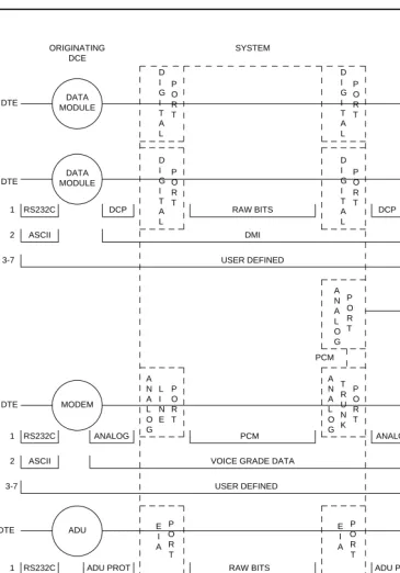
The originating DTE equipment can also add layer-2 code to be analyzed by the destination DTE equipment. The DCE equipment treats this layer as data and passes it along to the destination DTE equipment as it would any other binary bits. Refer to Figure 1-2.
Layers 3 to 7
Maintenance Concepts for DEFINITY ONE
1-18 Maintenance testing
1
Figure 1-2. Data transmission states DCE
ORIGINATING
DCE DESTINATION SYSTEM
RS232C DCP RAW BITS DCP RS232C
1 DTE
2 ASCII DMI ASCII
3-7 USER DEFINED
D I G I T A L P O R T D I G I T A L P O R T D I G I T A L P O R T D I G I T A L P O R T DATA MODULE DATA MODULE DATA MODULE DATA MODULE DTE DTE DATA MODULE DS1 PORT 1 D I G I T A L P O R T RAW BITS
RS232C DCP DS1 FORMAT
DMI ASCII 2 P O R T D S 1 DTE T R U N K P O R T A N A L O G ADU ADU DTE E I A P O R T E I A P O R T DTE DMI
ASYNCH ASCII ASYNCH ASCII
2
3-7 USER DEFINED
RS232C ADU PROT ADU PROT RS232C
1 RAW BITS
3-7 USER DEFINED
VOICE GRADE DATA
ASCII ASCII
2
ANALOG ANALOG
1 RS232C PCM RS232C
P O R T A N A L O G L I N E A N A L O G P O R T DTE DTE MODEM POOLING CABLE MODEM MODEM MODEM PCM
Maintenance Concepts for DEFINITY ONE
1-19 DEFINITY LAN Gateway maintenance
1
DEFINITY LAN Gateway
maintenance
The DEFINITY LAN Gateway (DLG) provides connectivity for ASAI to CentreVu CT without using the C-LAN board. Connectivity is provided between DEFINITY ONE and CentreVu CT using the interface on the TN795 Circuit Pack or
(optionally) the C-LAN TN799 Circuit Pack.
A CLAN board is normally used only if a private LAN is required for security reasons. For this release of the DLG feature, only one of the interfaces (TN795 or C-LAN) can be used on the same system.
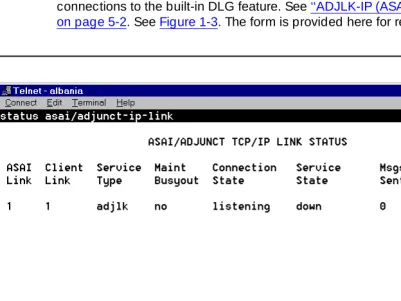
The status asai/adjunct-ip-link form is used to obtain a summary of the
connections to the built-in DLG feature. See ‘‘ADJLK-IP (ASAI Adjunct IP Link)’’ on page 5-2. See Figure 1-3. The form is provided here for reference only.
Maintenance Concepts for DEFINITY ONE
1-20 DEFINITY LAN Gateway maintenance
1
When a service is administered on the ip-services form, the service type and link number are combined into a single keyword entry, for example, ADJLK1.
However, on the above form the link number (1 in ADJLK1) is shown separately from the link or service type (ADJLK in ADJLK1). The client’s link number is also shown for convenience. When using the TN801, this value is administered in DEFNITY as well as in the ASAI client. When using the DLG function, the client link number, assigned only in the client, is obtained by DEFINITY from the protocol and displayed on this form. It is not administered within DEFINITY.
DLG test
A test of these links is supported. The test causes a TCP-Tunnel Heartbeat message to be sent from DEFINITY and a Heartbeat Reply message to be returned from the client. See Figure 1-4. The form is provided here for reference only.
Maintenance Concepts for DEFINITY ONE
1-21 DEFINITY LAN Gateway maintenance
1
Busyout and release
Both busyout and release-from-busy commands are supported. The busyout command causes a message to be sent to the client to stop using the link. See
‘‘busyout adjunct-ip-link’’ on page 4-4.
The Release commands cause a message to be sent to the client indicating that link can again be used. See‘‘busyout adjunct-ip-link’’ on page 4-4. These commands do NOT busy out the TCP/IP connection. See Figure 1-5.
Maintenance Concepts for DEFINITY ONE
1-22 DEFINITY LAN Gateway maintenance
1
Maintenance Concepts for DEFINITY ONE
1-23 Processor C-LAN maintenance
1
Processor C-LAN maintenance
The Processor C-LAN provides TCP/IP connectivity to DEFINITY ONE using the Ethernet interface on the TN795 Processor Board. This is similar to the use of the C-LAN Board, except that the processor interface is specified. The Processor C-LAN connectivity is an option for specified applications, such as TCP/IP, DCS, EMS, and the DLG feature.
Administration and maintenance
Before the LAN interface on the TN795 processor card can be used, it must be enabled on the customer options form. See Figure 1-7.The form is provided here for reference only.
Figure 1-7. Processor ethernet customer option entry
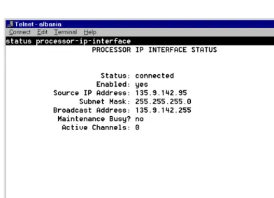
The status, busy, and release-from-busy commands are available for the Processor Ethernet interface.
For the status command, see ‘‘status asai/adjunct tcp/ip link’’ on page 4-140. See
Maintenance Concepts for DEFINITY ONE
1-24 Processor C-LAN maintenance
1
Figure 1-8. Processor interface status
For the busyout command, see ‘‘busyout adjunct-ip-link’’ on page 4-4. See
Maintenance Concepts for DEFINITY ONE
1-25 Processor C-LAN maintenance
1
Figure 1-9. Processor busyout command results
For the release-from-busy command, see ‘‘busyout adjunct-ip-link’’ on page 4-4. See Figure 1-10. This form is provided here for reference only.
Maintenance Concepts for DEFINITY ONE
1-26 Media processor
1
Media processor
The MedPro board is the TN802B version of the MAPD circuit pack, when operating as a media processor. See ‘‘MEDPROPT (TN802 MED PRO DSP PORT)’’ on page 5-782.
Accessing DEFINITY ONE™ for
maintenance
There are several ways to connect to the DEFINITY ONE system.
■ Web browser interface ■ Telnet session
■ pcAnywhere
■ DEFINITY Site Administration
This section describes these types of interfaces and when it is appropriate to use them. For more information, see Chapter 2, “Connectivity and Access to
DEFINITY ONE” in DEFINITY ONE Communications System Release 2.0 Installation and Upgrades (555-233-109).
Web browser interface
You can perform basic maintenance and administration functions on the DEFINITY ONE from a standard web browser (such as Netscape Navigator).
■ Backup ■ Restore ■ Restart
■ Start pcAnywhere host and client applications. ■ Download software
— DEFINITY Site Administration (DSA)
— DEFINITY Message Manager
Figure

Related documents
While DEFINITY switch Version 4, Version 5, and Release 6 recognized earlier DEFINITY AUDIX system releases’ TN566 or TN567 circuit packs as belonging to the DEFINTY AUDIX
In addition, this chapter contains technical descriptions important to the general maintenance of High and Critical Reliability systems, such as a list of the appropriate
If an A500 port to which a DEFINITY port network is attached is not listed in this display, it is likely that the port was administered incorrectly as having no UNI signaling
If the ISDN-PRI trunk is of type "cbc," make sure the TestCall Service field on the Trunk Group Administration Form indicates the correct service so that a network
Destination Port This number must match the Interface Channel number assigned on the Switch-1 Processor Channel screen Session - Local For each connection, the Local Session number
Warning alarms are generated (error type 18) on each maintenance object busied out, so that INADS can access the state of the objects. The
Type configure tape spe-a large and press Enter to reconfigure the removable media in control carrier “A” for 2 TN1650B Memory circuit packs.. Type configure tape spe-b large
A printer, personal computer or tape unit (Data Terminal Equipment) — An MPDM to a port on a TN754 digital line circuit pack or a 212A- type modem to a port on a TN742 analog
