Performance Analysis of ZF Pre-Coder and Extended Joint
Channel Estimation Method in Downlink CDMA with HPA
S. Ghavami* and B. Abolhassani*
Abstract: In the down link scenario of CDMA systems, Linear De-Correlating Detectors
(LDDs) provide satisfactory Symbol Error Rates (SERs), but they require all active users’ spreading sequences, which is impractical from privacy perspective. To overcome this impracticality, a simple matched filter receiver is considered in this paper. However, this receiver degrades the SER due to Multiple Access Interference (MAI). So, a Zero Force (ZF) pre-coder is employed in the transmitter to improve the SER. Moreover, we consider the Non-Linear Distortion (NLD) caused by the High Power Amplifier (HPA) of the Base Station (BS) due to large Peak to Average Power Ratio (PAPR) of the composite of CDMA signals. We analyze the down link of the proposed system to derive an equation for its SER. Theoretical analysis and numerical results show that the ZF pre-coder increases the total degradation of the link significantly compared with that of the LDD. So, as a solution, rather than ZF pre-coder, we propose a new method called extended joint channel estimation in which joint estimation of channel gains and LDD operator are used by the mobile station (MS). In this case, the BS transmits row k of LDD operator to MS k. Simulation results show that the SER of this new proposed method is close to that of the LDD in Additive White Gaussian Noise (AWGN) channel with the added advantage of no need for spreading sequences of all co-users.
Keywords: High Power Amplifier, Nonlinearity, Distorter, PAPR, CDMA, ZF
Pre-Coder.
1 Introduction1
Code division multiple access (CDMA) is employed in the third generation of mobile networks to provide multimedia services with required qualities. A multi-user detector (MUD) is used to detect the desired signal and to simultaneously cancel out the interferences coming from co-users [1]. To do this, a non blind MUD requires the user's, as well as all co-users’ spreading sequences. Furthermore using MUDs in the receiver increases the complexity of the mobile station (MS). Moreover, knowledge about spreading sequences of co-users reduces the privacy and security of the CDMA networks. Traditionally, a zero force (ZF) pre-coder in the downlink scenario to be used in the transmitter of the base station (BS) with a simple matched filter as the receiver for the MS, in this case the knowledge about spreading sequence of co-users is not necessary in the receiver. Moreover, there is a major drawback in the downlink of a CDMA network, which is high peak to average power ratio (PAPR) of transmitted signal. This
Iranian Journal of Electrical & Electronic Engineering, 2013. Paper first received 10 Jul. 2012 and in revised form 2 Feb. 2013. * The Authors are with the Department of Electrical Engineering, Iran University of Science and Technology, Tehran, Iran.
E-mails: [email protected] and [email protected].
PAPR results in nonlinear distortion (NLD) due to using an HPA in the transmitter, which degrades the performance of the MS receiver. Furthermore, low PAPR transmission has more consistency with new technologies in the wireless communication such as cognitive radio technology, which needs limited level of interference in the in-band and out-band to provide spectrum opportunity for transmission of secondary users. Moreover, one of new paradigm in telecommunications is green power communication, in which the limitation on peak power of signals has important role in providing constraints of green power communication.
Conti and Dardari analyzed the effects of the HPA on the SER of downlink scenario in CDMA systems using matched filter detectors in AWGN channels [2]. In [3], Rugini and Banelli performed a similar work to that of [2], but for MUDs. In [4] and [5], we studied the SER performance of MUDs in terms of output back off (OBO) in the HPA over AWGN plus flat fading channels. In [6] we studied effects of non-ideal pre-distorter HPAs on the performance of MUDs in WCDMA systems. In [7], nonlinear multiuser receiver for optimized chaos-based DS-CDMA systems is proposed. In [8] convolutional spreading CDMA has
been used for MAI cancellation and limiting the PAPR of transmitted signal. A pre-distorter can alleviate NLDs of the HPA. When the input back off (IBO) is very high, the output signal experiences no saturation at the expense of being power inefficient. For this reason, Ryu in [9] analyzed the SER of a predistorted orthogonal frequency division multiplexing (OFDM) system over AWGN channels. In [10], the SER performance of a system using MMSE pre-coder in the transmitter and a matched filter in the receiver was analyzed and compared with that of a similar system using an ideal pre-distorted transmit amplifier and a MUD. As well, in [12] the performance of the ZF and MMSE pre-coder system without considering HPA was investigated through computer simulations. Also, in [11] the performance of linear precoding and linear MUD have been compared in the downlink of time division duplex-CDMA (TDD-duplex-CDMA) systems and show that precoding can outperform the more complex MUD. But, [12] consider ideal HPA (no NLD) in the performance analysis of the linear pre-coder such as ZF precoding.
In this paper, the SER performance of the downlink scenario with ZF pre-coder is analyzed in the presence of HPA nonlinearity, and this SER is validated over AWGN plus flat fading channels using simulations. Furthermore, these results are compared with those of a linear de-correlating detector (LDD), and a minimum mean square error (MMSE) detector of CDMA systems, which were studied in [13] precisely. By deriving the SER of this link, we will see that using a ZF pre-coder in the transmitter with a simple matched filter as the receiver increases the total degradation of the system, which is a key performance index measuring quality of communication systems in the presence of NLD. As a solution for this problem, we propose a new strategy which is called extended joint channel estimation method. It is based on joint estimation of channel gains and LDD operator by the BS. In this new strategy, the multiplication of the row k of the cross correlation matrix of the spreading sequences with the spreading sequence of user k have been sent to each active user by the BS. This new strategy avoids increasing the PAPR of transmitted signal. So, there is no need to using the ZF pre-coder in transmitter when a simple receiver is used. In the proposed strategy, calculation of the inverse cross correlation matrix of the spreading sequences now can be done in the BS. As well, this strategy requires only the spreading sequence of the desired user. The performance of our proposed strategy is evaluated using computer simulations. Moreover, the number of required pilot symbols for the proposed strategy is derived using computer simulations. Finally, loss in the spectral efficiency due to transmitting pilot symbols is analyzed in terms of traffic load variations.
The remainder of this paper is organized as follows. In Section 2, the system model is described. In Section 3, we analytically derive the SER of the system using
ZF pre-coder in the base station and a simple matched filter receiver in the MS and the derived SER is validated using computer simulations. In Section 4, a method for joint estimation of channel gains and LDD operator is proposed to limit the level of PAPR of the transmitted signal, the performance of the proposed method is evaluated in the presence of HPA in the transmitter, also performance of that is compared with similar scenario, in which LDD is used in the receiver. Finally, in the last section, conclusions are presented.
2 System Model
We consider the downlink of a CDMA system; the composite of active users’ signals in the base station is given by
1
1 0
( ) 1 [ ] [ ] ( ),
K N
k k k c
k j m
z t A d j m p t mT jT
N
+∞ − = =−∞ =
=
∑∑∑
c − − (1)where N is the processing gain; K is the number of active users; Ak, [ ]d jk and [ ]ck m denote, respectively
the amplitude, data symbol j, and chip m of the spreading sequence (ck[ ] 1m = ) for user k; ( )p t is the chip pulse shaping waveform with unit energy, T denotes symbol time, and Tc =T / N is the chip time. Data symbols
{
dk[ ]j}
of different users are independent and identically distributed (i.i.d.). In the following of this paper, a bold capital letter denotes a matrix (A), abold small letter denotes a vector (a), and letters not
bolded denote scalar values (A, a). The symbol l of the transmitted signal in the matrix form is given by
[ ]
[ ]l = l ,
z CAd (2)
where C=[ , ...c1T , cTK], ck =
[
]
0.5 [0],..., [ 1]
− −
k k
c c
N N , A=diag( ,...,A1 AK) and
[ ] [
1[ ], [ ],..., [ ]2 K]
Tl = d l d l d l
d . For MAI cancellation in
the downlink scenario, the pre-coding techniques in the transmitter can be good candidates for replacing instead of multi-user detectors. So, the pre-coder matrix and the corresponding transmitted signal is computed in the transmitter. Using linear pre-coder for the data vector, the pre-coded data vector can be computed as:
[ ]
l =[ ]
l ,b Td (3)
where T is the coder matrix. By spreading the
pre-coded data, the transmitted symbol l, i.e. x
[ ]
l , is given by:[ ]l = [ ],l
x CAb (4)
hence, pre-coded transmitted signal can be computed as:
1
1 0
( ) 1 [ ] [ ] ( ).
K N
k k k c
k j m
x t A b j c m p t mT jT
N
+∞ − = =−∞ =
=
∑∑∑
− − (5)The signal x t( ) is entered to the HPA, whose output is denoted by ( )y t . The characteristics of a HPA are given in [14] by its amplitude to amplitude (AM/AM) and amplitude to phase (AM/PM) distortion functions, which are denoted by GHPA( )⋅ and ϕHPA( )⋅ ,
respectively.
Using these two functions, the base-band output of the HPA is given by:
(
)
( ) ( ( ) ) exp( ( ) ),
y t =G x t jϕ x t (6)
where ϕ
(
x t( ))
=ϕHPA(
x t( ))
+ x t( ), and x t( ) denotes phase of ( )x t . A pre-distorter amplifier may be used for the alleviation of the HPA nonlinearity. The amplitude transfer function L( )
⋅ and the phase transfer function ψ(.) of a pre-distorter are:( )
( )
( )
( )
-1 HPA
,
HPA
L G
ψ ϕ
⎧ ⋅ = ⋅
⎪
⎨ ⋅ = − ⋅
⎪⎩ (7)
in which, -1
( )
HPAG ⋅ is the inverse of GHPA( )⋅ in the
non-saturated region of the amplifier. If the pre-distorter works ideally, the combination of the HPA and pre-distorter can be modeled by a linear amplifier and a soft limiter. This model, which is called ideal pre-distorted amplifier (IPA), given by GHPA(| |) | |x =x for | |x A≤ sat,
(| |)
HPA sat
G x =A , for | | x >Asat and ϕHPA(| |) 0x = ,
is considered in next section for the SER analysis. In Chapter 12 of [15], it has been noted that if ( )x t has Gaussian distribution, ( )y t may be decomposed into a linear amplification of ( )x t plus a nonlinear distortion noise based on Bussgang Theorem. In the mathematical language, it can be expressed by:
( 0 )
arg ( ) 0
( ) j t ( ) d( ),
y t =αe α x t +n t (8)
where α0 and n td( ) are linear amplification gain and
nonlinear distortion, respectively. The output of the channel ( )r tk to the input ( ),y t is given by:
,
( ) ( , ) ( ) ( )
( ) ( ),
k k k k k
sig k k
r t h t y t d n t
r t n t
τ τ τ
+∞
−∞
= − +
= +
∫
(9)where ( , ) ( ) jk( )t
( )
k k k k
h τ t =β t eθ δ τ is the channel impulse response to the impulse applied at t−τk,
( )
, ( ) ( ) 0 k ( )
j t
sig k k
r t =β t α eθ x t denotes the useful signal,
, ,
( ) ( ) ( )
k NL k AWGN k
n t =n t +n t , where
( )
, ( ) ( ) k ( )
j t
NL k k d
n t =β t eθ n t is the nonlinear distortion
noise and nAWGN k, ( )t is AWGN with zero mean and variance of 2
AWGN
σ .
In this paper demodulation is considered coherent, also time and frequency synchronizations are assumed perfect. The channel phase θk and the mean HPA
phase-shift arg( )α0 are also considered to be perfectly
known to the receiver. Samples of channel are considered to be constant for any symbol; such that for symbol l, the channel gain is defined by βk
[ ]
l =βk( )lT .By defining r[ ]l =
[
r l1[ ],..., [ ]r lK]
T,[
1]
[ ]l = n l[ ],...,n lK[ ]T
n , it can be shown that the output
of the code-matched filter, which is the cascade of a chip-matched filter and a de-spreader, is given by:
[ ]
[ ]
( 0 )
[ ]
,
2 arg ( ) 0
[ ]
[ ] [ ] ,
k sig k k
j lT H
k k
l l l
e α l l l
α β
= +
= +
CAb
r r n
C n
(10) where nk
[ ]
l = βk[ ]l 2C nH d[ ]
l +C nH AWGN k,[ ]
l , in which nd[ ]
l =⎣⎡n lTd( ) L nd N, −1(lT +(N−1) )Tc ⎤⎦,[ ]
, , ( ) , (
AWGN k l =⎡⎣nAWGN k lT nAWGN k lT +
n L
]
(N−1) )Tc and ( )⋅H stands for conjugate transpose
operation. The ZF solution is:
1
−
=
T R , (11)
The main drawback of using pre-coder is boosting the transmit power [10]. Hence, the transmitted signal is scaled at the transmitter. The scaling factor is determined based on available transmit power, so that the average transmit power with and without pre-coder become equal [10, 16]. The average transmit power without pre-coder can be computed as:
[ ]
[ ] [ ]
2 (without precoding)
( ) ( )
t
H H
H
H
P l
l l
tr tr K =
=
=
=
Cd d C
CC
C C
x
=
. (12)
where tr( )⋅ stands for trace operation. The average transmit power with pre-coder can be computed as:
[ ]
[ ] [ ]
2 (with precoding)
=
= Cb b C
x
t
H H
P l
l l
[ ] [ ]
(
)
1 1
1
{ }
{ }
− −
−
=
= =
CTd d T C
CR CR
R
H H H H
l l
tr
tr
.
(13)
The signal scaling factor which is denoted by αZF,
satisfy the:
2
(with precoding) (without precoding).
ZFPt Pt
α = (14)
From Eq. (14) and using Eqs. (12, 13), the scaling factor αZF is obtained as:
1 .
{ }
ZF
K tr
α = −
R (15)
The other drawback of using pre-coder is increasing the PAPR of the transmit signal, which generates nonlinear distortion at HPA output and degrades the SER of the system. This effect is considered precisely in next section of this paper.
Some definitions which are used in the remainder of this paper are defined as follows, the peak to average power ratio (PAPR) for the input signal ( )x t is defined as PAPR=max{ ( ) }x t 2 E x t{ ( ) }.2 For a HPA, the input back-off (IBO) is defined as
2 , { ( ) }, x sat
IBO P= E x t where Px sat, is the minimum
input power that saturates the HPA. Similarly, the output back-off (OBO) is defined as
2
, [ ( ) ]
y sat
OBO P= E y t , where Py sat, is the maximum output power of the HPA. The nonlinear distortion is generated at the transmitter should be considered in the conventional SNR. For this purpose, the conventional SNR is defined as the apparent signal-to-noise ratio SNRapp measured at the receiver input, which is
(
2 2)
2app SIG NL AWGN
SNR = σ +σ σ [2]. In this equation,
[ ]
22 { }
NL E NL l
σ = n and σAWGN2 =E{nAWGN
[ ]
l 2}. Inthis equation, nonlinear distortion is added to the signal power, hence SNRapp is not a proper definition for the
SNR. For this reason, in [2] SNR that is eff
(
)
2 2 2
SIG AWGN NL
σ σ +σ is used rather than SNRapp.
The total degradation (TD) in a target SER is key performance measure in communication systems with HPA, which is defined as [2].
[ ]
TD dB =(
⎡⎣SNRapp⎦⎤dB−[
SNReff]
dB)
+[
OBO]
dB, (16)where the difference of the terms inside the parentheses indicates the power penalty and the OBO indicates the power penalty with respect to the saturating output power of the amplifier. There is a trade-off between these two power penalties, since an increase in OBO results in a smaller distortion.
3 SER Analysis in Nonlinear Channels
In this section, first we derive the SER of the system using ZF pre-coder in the base station and a simple matched filter receiver in the MS analytically in
subsection 3.1. Then and the derived SER is validate using computer simulations in subsection 3.2.
3.1 Analytical Results
In the downlink scenario, if signals are transmitted with the same power, then the signal received from each user has equal amplitude. This guarantees that the average signal-to-interference ratio (SIR) received by each MS is the same. Moreover, by considering equal average amplitude for the signal and each MAI and by having a large number of users, (e.g., K >7), it is possible to approximate ( )x t by a Gaussian-random process [1].
By periodic considering the spreading waveforms of all MSs, the HPA input composite signal ( )x t can be approximated by a cyclostationary Gaussian random process. In this case, the linear component α0x t( ) and
the nonlinear one n td( ) in Eq. (8) are mutually uncorrelated [2]. So, the autocorrelation function of the HPA output signal, ( )y t can be evaluated as
2 0
( ) ( ) ( ),
y x nd
R τ = α R τ +R τ where all the quantities are averaged over the cyclostationary period T and
2 2
0 0 x
α =γ σ . Using [17] it can be shown that
(
)
2 12 1
( ) ( ) i
nd i i x x
R τ +∞γ R τ σ +
=
=
∑
in which thecoefficients γis, i≥0, depend on the HPA function
and the HPA input power 2 x
σ . In [17], in case of IPA model, closed from expressions for γis are given by
considering Gaussian approximation for input signal. In the NLD analysis of the ZF pre-coder output, we cannot include PAPR increment of ZF pre-coder technique in our analysis since PAPR varies due to variation in the distribution of the input signal while we approximated input signal by a cyclostationary Gaussian process for simplicity of our analysis, with a given input power 2
x
σ . Therefore, to overcome this problem in analysis, we define a new parameter for the IBO of the amplifier in which the effect of PAPR increment is excluded, and its effect is considered in the pre-coded signal. For this purpose, we define a new parameter,
Virtual HPA
IBO for the IBO, which is given by:
Virtual HPA
Real HPA effective ,
dB
dB
IBO
IBO PAPR
=
⎡ ⎤
⎣ ⎦
−
⎡ ⎤
⎣ ⎦ , (17)
where all above variables are expressed in terms of dB. In (17), IBOReal HPA is the actual value of the IBO for
the HPA and PAPReffective is defined as:
effective Increment,
PAPR =κPAPR (18)
in whichPAPRIncrement is the PAPR increase due to
using the ZF pre-coder and κis a constant regulator whose value depends on both coded and non pre-coded signal distributions and is defined by:
{
}
{
} {
}
{
}
{
}
2 2 2 2 2Pr ( ) 0,
Pr ( ) Pr ( )
Pr ( )
Pr ( ) 0,
0, Sat Sat Sat Sat Sat input input input input input
if x t P
x t P z t P
x t P
if x t P
κ
⎧ > ≠
> − >
= > > = ⎪ ⎪ ⎪ ⎪⎪ ⎨ ⎪ ⎪ ⎪ ⎪ ⎪⎩ (19)
In which, Pr
{}
⋅ denotes probability function,⋅ stands for absolute value and PSatinput is the saturatedinput power of HPA. Using PAPReffective makes our
analysis robust against instantaneous sparks of the signal amplitude, which occur with low probability values and has no significant effect on the average SER. It is probabilistic weighting for PAPRIncrement. The
power of NLD without pre-coder is given by:
2 2 1
,
1
(0) nonprecode (0)i ,
NL nonprecode nd i z
i
R R
σ +∞γ +
=
= = ∑ (20)
where, nonprecode i
γ is the calculated γi without considering effect of pre-coder with real HPA characteristics, 2
NL
σ with pre-coder is obtained as:
2 2 1
,
1
(0) precoded (0)i ,
NL precoded nd i x
i
R R
σ +∞γ +
=
= = ∑ (21)
where, precoded i
γ is calculated with pre-coder with virtual HPA characteristics by substituting IBOVirtual HPA
instead of IBO . Also, the transmit power of ( )x t is equal to that of ( )z t by power scaling, i.e.
(0) (0)
x z
R =R . In this case, the operation of pre-coder is correlation eliminating of different users’ spreading sequences, hence it causes PAPR of input signal increases. Therefore, IBOReal HPA is reduced to
Virtual HPA
IBO , it causes signal to nonlinear distortion ratio (SNDR) decreases, which is given by:
0 2 1 1 (0) . (0) x i i x i R SNDR R γ γ +∞ + = =
∑
(22)Hence, SER performance of pre-coded signal degrades in comparison with that of un-pre-coded signal due to reduction in the SNDR; in the following, both our theoretical and numerical results confirm this conjecture.
Now, the SER of the system in nonlinear channels (due to using HPA) is analyzed over AWGN and flat fading plus AWGN channels for a simple matched filter along with ZF pre-coder in the transmitter. The SER can be expressed in a closed form by modeling both the MAI and the nonlinear distortion noise in the output of HPA as Gaussian random variables. In this case, for the QPSK modulation, we can obtain the SER of the desired user to be as [18].
, ,AWGN detector,
2
detector,
2 ( SNR )
( SNR ),
e k k
k
P Q
Q
=
− (23)
where 2
(
2 2 2)
detector, , , , ,
SNR k =σSIG k σMAI k+σNL k+σAWGN k ,
in which 2 ,
σSIG k and
2 ,
σMAI k are power of linear amplified signal and power of MAI, 2 2
,
σNL k =σNL and
2 2
,
σAWGN k=σAWGN for ZF pre-coder in the transmitter and matched filter in the receiver.
The SER, conditioned toβ, can be approximated as [18].
, ( ) 2 ( SNRdetector, ( )),
e k k
P β ≈ Q β (24)
where SNRdetector,k( )β =
(
)
2 2 2 2 2 2 2
, , , ,
β σSIG k β σMAI k+β σNL k+σAWGN k . For practical symbol-error probabilities (i.e., when 2
, ( ) 10 e k
P β ≤ − ).
The average SER, Pe k, ( )β is obtained by averaging
over the probability distribution function (PDF) of the channel gain i.e. Rayleigh distribution, is given by:
2
2 2
2
, , 2 2 2
0
2 ( ) ,
( ) 1
k e k Flat
k
P Q β γ βe β dβ
β η δ
+∞ − ≈ + +
∫
(25) where 2 2 0 2 2 k k AWGN A α γ σ = , 2 2 2 MAI k AWGN σ δ σ = , 2 2 2 NL AWGN σ η σ = .This integral is calculated in [19] and the final SER can be expressed as:
(
)
2
, , 2 2
2
2 2 2 3/ 2
0
2 2 1
2
1 exp( )
2 2( )
2 1
( )
! ( )
3
( , 2,( ) ),
2
k
e k FLAT k
k m k m k m k P m
U m m
γ γ η δ γ η δ η δ +∞ + = − − = − + × + × + + +
∑
(26)where U is confluent hyper geometric function which is given by relation 13.1.3 in [20]. In this paper, this integral includes effects of ZF pre-coder on the SER.
In [12], effect of nonlinear distortion is considered when linear multi-user detectors i.e. LDD and MMSE detector are used in the receiver. We compared our
analytical results for the ZF pre-coder with matched filter in the receiver with these results, and our analytical results are confirmed using computer simulations in the following subsection. The power of nonlinear distortion and AWGN of the output of the LDD, MMSE and matched filter are obtained in [12].
3.1 Simulation Results
To confirm the validity of Eqs. (23, 26), derived in our analysis, we use computer simulations. We consider an IPA model for the HPA. A rectangular pulse shaping waveform ( )p t is used. The type of modulation is QPSK. The base station transmits data with equal amplitudes for each of K = 25 users. Gold-sequences with length of 63 have been used for short spreading codes of all active users. Computer simulations are done for two different channels: AWGN and AWGN plus flat fading.
Table 1 shows the PAPR of the transmitted signal with and without pre-coder for 25 equal power active users. It is obvious that there is 1.38 dB increament for the PAPR value in the transmitted signal due to using pre-coder.
Table 1. PAPR of the transmitted signal with and without pre-coder for 25 active users employing Gold spreading sequences
Scenario Without pre-coder With pre-coder
PAPR [dB] 12.46 13.84
Fig. 1 shows the SER of the ZF pre-coder and matched filter in the receiver as a function of SNRapp
over AWGN channels. Our theoretical results of ZF pre-coder in transmitter with matched filter in receiver have good agreements with those of simulations, which validate Eq. (23).
Fig. 2 shows the SER of the ZF pre-coder and matched filter in the receiver as a function of SNRapp over AWGN plus flat fading channels. Our theoretical results for ZF pre-coder in the transmitter and a matched filter receiver have good agreements with simulations results, which validate Eq. (26). In the legends of Figs. 1 and 2, “S” and “A” are related to the SERs, which are obtained using computer simulations and analytical results, respectively.
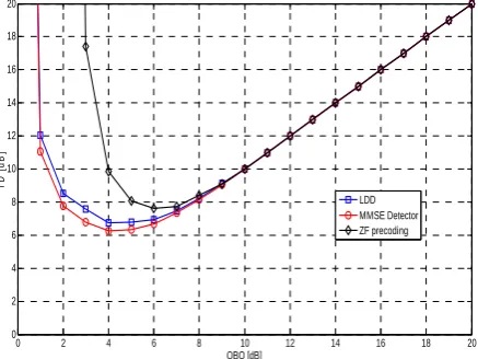
Fig. 3 shows TD in dB over AWGN channel for SER = 10-3. It is obvious that the TD in ZF pre-coder is
the worst case, it is result of PAPR increment, which is consequence of using ZF pre-coder, and it confirms our theoretical analysis in previous subsection. Fig. 4 shows the TD in dB over AWGN plus flat fading channel for SER = 10-3. It is obvious that the TD in ZF pre-coder is
the worst case, it is result of PAPR increment, which is consequence of using ZF pre-coder, which is confirmed our theoretical analysis in previous subsection.
Fig. 4 shows the total degradation (TD) in dB over flat fading channel for SER = 10-3. Similar to the
AWGN channel, the TD in ZF pre-coder is the worst
case. In flat Rayleigh fading scenarios, increasing useful signal power increases the NLD noise. It can be seen in Figs. 3 and 4, the TD in flat fading channels is less than that of AWGN channels for all receivers. It is notable that curves in Figs. 3 and 4 have two parts. In the first part, by increasing the OBO, the TD decreases until it reaches to its minimal value, and then in the second part it starts increasing.
The TD can be derived theoretically using Eqs. (23, 26) in the AWGN and flat Rayleigh fading channels, respectively, for a given value of SER. Hence, the minimal TD calculated by using theoretical results can be used as the optimal OBO for the HPA in the designing of HPA.
Our simulation results have shown that using the ZF pre-coder results increasing the PAPR and more TD relative to the case of without ZF pre-coder, which is confirmed by both analytical and simulation results. It results due to cancellation of the correlation among spreading codes in the transmitter. In the next section, a method for MAI cancellation is proposed without PAPR increment. It is based on a joint estimation of channel gains and the rows of the LDD operator. The proposed method does not increase the PAPR of the transmit signal unlike the ZF pre-coder. As well, it can cancel MAI in the down link without knowledge about both spreading sequences of all active users and calculations of R−1, which are required for multi-user detection.
4 Joint Estimation of Channel Gains and LDD Operator
As shown in the previous section, the ZF pre-coder increases the PAPR of transmitting signals; it degrades the TD, which is shown by analytical and simulation results. In this section, a method is proposed for MAI cancellation of MSs in the downlink scenario. This method overcomes the problem of PAPR increase due to using linear pre-coder in the transmitter. It is notable; a simplified version of this method has been used partly by authors for the CDMA systems, which uses transmitter with multiple antennas and without presence HPA in [21].In this paper, the channel gains are estimated in the MSs with a period less than the coherence time periodically. The proposed method is based on a new joint estimation of channel gains and the rows of the LDD operator. In the down-link scenario, each MS knows only its own spreading sequence and doesn’t have any knowledge about spreading sequences of any other MSs, but the LDD operator which is given by:
1
LDD = − T
D R C , (27)
requires the knowledge of spreading sequences of all other active users. Furthermore, even if a MS knows the code matrix of all users (e.g.C) yet it needs to calculate
the inverse cross correlation matrix of spreading sequences of all active users (i.e. -1
R ), which has high
computational complexity. Moreover, the MS has
permission to detect only its own data while based on Eq. (27) all the elements of the DLDD can be calculated
in the MS, which jeopardize the communications security for other users. As well, the user k requires only row k of the DLDD, which is denoted by
(
DLDD)
k,:, indetected data symbol l of user k , which can be seen in the following equation:
Fig. 1 SER performance of the ZF pre-coder in AWGN channels for different values of OBO
Fig. 2 SER performance of the ZF pre-coder in flat fading channel for different values of OBO
Fig. 3 TD in dB for three receivers in AWGN channels
Fig. 4 TD in dB for three receivers in flat fading channels
(
)
2,:[ ] ,: [ ] [ ] [ ],
k l = LDD k βk l b l + ′l
v D CA n (28)
where n′ =[ ]l
(
DLDD)
k,:n[ ]l . To obtain(
DLDD)
k,: in the receiver, a new method is proposed in this paper, in which the base station sends(
DLDD)
k,: to the MS through a pilot signal periodically, whose period is much greater than the symbol time since the number of MSs varies much slower than the symbol time. Moreover, the base station spreads the pilot signal for transmitting(
DLDD)
k,: using kth spreading sequence.
This strategy cancels out the MAI, without any PAPR increase in the transmitted signal due to the ZF pre-coder. This strategy maintains the system security since only the kth MS can obtain the
(
LDD)
,:k
D for detecting its
data. The received pilot symbol is as follows,
[ ] [ ] [ ],
pilot
k k
l =A l ⊗ k+ ′′l
r β c F n (29)
where r [ ]= ⎣⎡0 [ ],..., −1[ ]⎤⎦
pilot N
T pilot pilot
l r l r l , Fk =ck
(
DLDD)
k,:,[ ]
[ ]
′′ k⊗
n l = c n l and ⊗ denotes element by element multiplications of two vectors. If Ak =1 then r [ ]
pilot
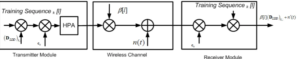
l will be equal to [ ]βlFk+n′′[ ]l . The MAI in the receiver can be cancelled out and channel gain effect can be compensated by knowing [ ]βlFk. Fig. 5 shows the block
diagram of the proposed strategy for joint channel estimation and LDD operator, in which Training sequencek [l] denotespilot symbol l of user k. The pilot
symbols, which can be used for estimation of the LDD operator, have been sent in non-overlapping time slots. Data sequences of active users have not been sent during the transmission of pilot signals, hence each pilot signal doesn’t have high PAPR, and so the pilot signal is amplified linearly. Furthermore, the MAI is not generated due to the transmission of pilot signals in non-overlapping time slots.
0 5 10 15 20 25 30 35 40
10-5
10-4 10-3 10-2
10-1 100
SNRapp [dB]
SER
ZF Precoding
OBO = 0 dB, S OBO = 1 dB, S OBO = 2 dB, S OBO = 3 dB, S OBO = 4 dB, S OBO = 5 dB, S OBO = 6 dB, S OBO = 7 dB, S OBO = 8 dB, S Linear, S OBO = 0 dB, A OBO = 1 dB, A OBO = 2 dB, A OBO = 3 dB, A OBO = 4 dB, A OBO = 5 dB, A OBO = 6 dB, A OBO = 7 dB, A OBO = 8 dB, A Linear, A
0 10 20 30 40 50 60
10-5 10-4 10-3 10-2 10-1 100
SNRapp[dB]
SE
R
ZF Precoding
OBO = 0 dB, S OBO = 1 dB, S OBO = 2 dB, S OBO = 3 dB, S OBO = 4 dB, S OBO = 5 dB, S OBO = 6 dB, S Linear, S OBO = 0 dB, A OBO = 1 dB, A OBO = 2 dB, A OBO = 3 dB, A OBO = 4 dB, A OBO = 5 dB, A OBO = 6 dB, A Linear, A
0 2 4 6 8 10 12 14 16 18 20 0
2 4 6 8 10 12 14 16 18 20
OBO [dB]
T
D
[d
B
]
LDD MMSE Detector ZF precoding
0 2 4 6 8 10 12 14 16 18 20 0
2 4 6 8 10 12 14 16 18 20
OBO [dB]
TD
[
d
B
]
LDD MMSE Detector ZF precoding
SER
SNRapp[dB] 100
10-1
10-2
10-3
10-4
10-50
5 10 15 20 25 30 35 40
SNRapp[dB]
SER
100
10-1
10-2
10-3
10-4
10-5
0 10 20 30 40 50 60
If the number of pilot symbols for each user increases, the variance of n′′ in Eq. (29) is reduced,
hence a better estimation of
(
DLDD)
,:k can be exploited.
Estimation error of
(
DLDD)
k,: is reduced with theexpense of increasing the training duration from KT to qKT, where q is the number of pilot symbol repetition for the desired user. The number of pilot symbol is repeated with period of variation number of users in the network, which is much less than coherent time of channel.
It is notable that the LDD causes noise enhancement in the receiver side but this performance degradation is negligible for SNR greater than 20 dB. As a result, the SER performance of the LDD matches to that of MMSE detector in high SNR region approximately. Whereas,
the SER performance degradation of ZF pre-coder due to the increase of σ2
NL is observed in all values of SNR,
hence it is not negligible even in high SNR region. So finding a solution is necessary for requirements of using the LDD in the downlink scenario, which is need to the knowledge of spreading sequences of co-users in the MSs and simple receiver in MS side. The proposed method in this section presents a solution for these requirements. Furthermore, using the structure of LDD avoids form PAPR increment due to using the ZF pre-coder. The overall solution is using joint channel estimation and LDD. Both LDD and ZF require spreading sequences of co-users, while in the proposed method need to the spreading sequences of co-users is not necessary.
Fig. 5 Block diagram of proposed joint estimation of channel gains and LDD operator
The receiver estimates the channel gains in simulation based on minimum mean square (MMSE) estimator. Fig. 6 shows the SER performance of the LDD receiver and our proposed strategy for joint estimation of channel gains and the LDD operatorfor different values of q over AWGN channel without using HPA in the transmitter. It can be seen the performance of the proposed method has only 0.3 dB loss in comparison with the performance of the LDD in SER = 10-5 with number of pilot symbol repetition of
q = 4. Figs. 7 and 8 show the SER performance of our proposed strategy, which is joint estimation of channel gains and LDD operator,with q = 1 and q = 8, respectively, for different values of OBO over AWGN channel. It can be seen, in the presence of HPA, the proposed method with q = 8 has the same performance of LDD for different values of OBO over flat fading channels.
Fig. 9 shows the TD in dB of joint estimation of channel gains and LDD operator method with q = 1 and 8 over AWGN channel on SER = 10-3. It can be seen the
TD of the proposed method is matched with TD of LDD operator for q = 8. It is notable; TD performance shows only effect of nonlinearity and do not show accuracy of LDD operator estimation.
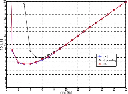
Fig. 10 is similar to Fig. 7, but the channel model has been considered flat fading. It can be seen, the proposed method in the presence of HPA with q = 1 has
the same performance of the LDD for different values of OBO over flat fading channels. Therefore, the multi-user detection using LDD can be performed without knowledge about spreading sequences and without PAPR increase of the transmitted signal in comparison with using ZF pre-coder.
Fig. 11 shows the TD in dB over flat fading channel on the SER = 10-3 for our proposed strategy with joint
estimation of channel gains and LDD operator and with q = 1. It can be seen the TD of proposed method is similar to the TD of the LDD.
The mean square error (MSE) of the proposed joint estimation of channel gains and the LDD operator is defined as,
(
)
,:( )
ˆ ,: 2 ,⎡ ⎤
= ⎢ − ⎥
⎣ DLDD k DLDD k ⎦
MSE E (30)
where
( )
,:
ˆ
DLDD
k is k
th row of the estimated LDD
operator, {}E⋅ denotes expectation operator and 2 denotes square norm of matrix . Fig. 12 shows MSE of the proposed joint estimation of channel gains and the LDD operator over AWGN in terms of number of pilot repetition q, for different values of SNR. It is obvious that by increasing q, MSE of
(
DLDD)
,:k estimation is
reduced.
Fig. 6 SER performance of LDD receiver and our proposed strategy for joint estimation of channel gains and LDD operatorfor different values of q over AWGN channel without using HPA in the transmitter
Fig. 7 SER performance of our proposed strategy for joint estimation of channel gains and LDD operator for q = 1 and different value of OBO over AWGN channel
Fig. 8 SER performance of our proposed strategy for joint estimation of channel gains and LDD operator for q = 8 and different value of OBO over AWGN channel
Fig. 9 TD in [dB] for joint estimation of channel gain and LDD operator, LDD and ZF pre-coder in AWGN channel
Fig. 10 SER performance of our proposed strategy for joint estimation of channel gains and LDD operator for q = 1 and
different value of OBO over flat fading channel
Fig. 11 TD in [dB] for joint estimation of channel gain and LDD operator, LDD and ZF pre-coder in flat fading channel
0 2 4 6 8 10 12 14 16 10-5
10-4 10-3 10-2 10-1 100
SNR [dB]
SE
R
q = 1 q = 2 q = 3 q = 4 LDD
0 5 10 15 20 25 30 35 40
10-5
10-4
10-3
10-2
10-1
100
SNRapp
SE
R
Joint channel estimation and LDD operator, q = 1
OBO = 0 dB OBO = 1 dB OBO = 2 dB OBO = 3 dB OBO = 4 dB OBO = 5 dB OBO = 6 dB OBO = 7 dB OBO = 8 dB OBO = 9 dB Linear
0 5 10 15 20 25 30 35 40 10-5
10-4 10-3 10-2 10-1 100
SNR
app
SER
Joint channel estimation and LDD operator, q = 8
OBO = 0 dB OBO = 1 dB OBO = 2 dB OBO = 3 dB OBO = 4 dB OBO = 5 dB OBO = 6 dB OBO = 7 dB OBO = 8 dB OBO = 9 dB Linear
0 2 4 6 8 10 12 14 16 18 20 0
2 4 6 8 10 12 14 16 18 20
OBO [dB]
T
D
[d
B
]
q = 1 q = 8 ZF precoding LDD
0 10 20 30 40 50 60 10-6
10-5 10-4 10-3 10-2 10-1 100
SNR
app
SE
R
Joint channel estimation and LDD operator
OBO = 0 dB OBO = 1 dB OBO = 2 dB OBO = 3 dB OBO = 4 dB OBO = 5 dB Linear
0 2 4 6 8 10 12 14 16 18 20 0
1 2 3 4 5 6 7 8 9 10 11 12 13 14 15 16 17 18 19 20
OBO [dB]
TD
[
d
B]
q = 1 ZF precoding LDD
SNRapp[dB]
SER
0 5 10 15 20 25 30 35 40 100
10-1
10-2
10-3
10-4
10-5
Fig. 12 Mean Square error of joint estimation of channel gains and the LDD operator in terms of training length over AWGN channel
Fig. 13 Mean Square error of joint estimation of channel gain and the LDD operator in terms of training length over Rayleigh flat fading channel
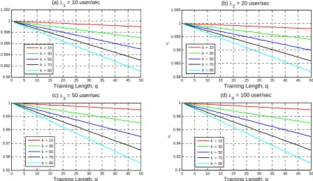
Fig. 14 Spectral efficiency in terms of required number of pilot symbol repetition for different number of active users in cell with (a) variation of input traffic of λ1=10user/sec, (b) λ2=20user/sec, (c) λ3=50user/sec and (d) λ4=100user/sec
Fig. 13 is similar to Fig. 12 but the channel model is considered Rayleigh flat fading, it can be seen in this Figure, by increasing the SNR, MSE has error floor, which is due to fading effect.
Now, the spectral efficiency of joint estimation of channel gains and LDD operator method is defined, which is:
1 ,
b
TIB qK
TTB R
λ
η= = − (31)
where TIBand TTBare transmitted information bit and total transmitted bit, respectively, also λ and Rb are
variation rate of number of arriving user to the cell and bit rate, respectively. Fig. 14(a) shows the η in terms of the used number of pilot symbolrepetition for different values of active users in the cell with traffic variation of
10 user / sec
λ= and Rb=5 Mbps. It is obvious even with q = 50 bits and k = 90 users, the spectral efficiency is greater than 0.99. Fig. 14(b) is similar to Fig. 14(a) with λ=20 user / sec, it can be seen with q = 50 bits and k = 90 users, the spectral efficiency is greater than 0.98. Fig. 14(c) and 19(d) are similar to Fig. 14(a) with
50 user / sec
λ= and λ=100 user / sec, respectively.
1 2 3 4 5 6 7 8 9 10 10-7
10-6 10-5 10-4 10-3 10-2 10-1 100
MS
E
SNR = 0 dB SNR = 3 dB SNR = 6 dB SNR = 9 dB SNR = 12 dB SNR = 15 dB
1 2 3 4 5 6 7 8 9 10 10-3
10-2 10-1 100
MS
E
SNR = 0 dB SNR = 3 dB SNR = 6 dB SNR = 9 dB SNR = 12 dB SNR = 15 dB
0 5 10 15 20 25 30 35 40 45 50
0.99 0.992 0.994 0.996 0.998 1 1.002
Training Length, q
η
(a) λ1 = 10 user/sec
k = 10 k = 30 k = 50 k = 70 k = 90
0 5 10 15 20 25 30 35 40 45 50
0.98 0.985 0.99 0.995 1 1.005
Training Length, q
η
(b) λ2 = 20 user/sec
k = 10 k = 30 k = 50 k = 70 k = 90
0 5 10 15 20 25 30 35 40 45 50
0.95 0.96 0.97 0.98 0.99 1
Training Length, q
η
(c) λ3 = 50 user/sec
k = 10 k = 30 k = 50 k = 70 k = 90
0 5 10 15 20 25 30 35 40 45 50
0.9 0.92 0.94 0.96 0.98 1
Training Length, q
η
(d) λ4 = 100 user/sec
k = 10 k = 30 k = 50 k = 70 k = 90
Training Length, q
Training Length, q
5 Conclusions
In this paper, the SER was derived analytically considering the transmitter nonlinearity in a CDMA system using a ZF pre-coder in the transmitter and a simple matched filter in the receiver for AWGN and slow flat Rayleigh fading channels. Eqs. (23, 26), derived analytically for the SER have good agreements with the simulation results, hence the validity of both equations is confirmed. Performance of the ZF pre-coder was compared with that of LDD and MMSE detectors without any pre-coder; the simulation and mathematical analysis showed that for any value of the SER the total degradation (TD) of the ZF pre-coder is more than those of both the LDD and MMSE detectors. Furthermore, an extended channel estimation method was proposed. It is based on joint estimation of channel gains and LDD operator, which can be used in the down-link scenario of the CDMA system without knowledge about spreading sequences of all active users. The proposed method keeps constant the PAPR of the transmitted signal, hence the SER performance is similar to that of LDD. Moreover, our analysis showed the loss in spectral efficiency of the proposed method is negligible for practical values of the traffic variation.
References
[1] Verdù S., Multiuser Detection, Cambridge Un.Press, 1998.
[2] Conti A., Dardari D. and Tralli V., “An analytical framework for CDMA systems with a nonlinear amplifier and AWGN,” IEEE Trans. on Communication., Vol. 50, pp. 1110-1120, July 2002.
[3] Rugini L., Banelli P. and Cacopardi S., “Theoretical analysis and performance of the decorrelating detector for DS-CDMA signals in nonlinear channels,” IEEE Trans. on Wireless Communication., Vol. 3, pp. 367-372, Mar. 2004. [4] Abolhassani B., Ghavami S. and Kahaei M. H.,
“Effects of transmitter nonlinearity on the performance of the decorrelating and MMSE detectors in CDMA cellular networks”, In Proc. of IST, Shiraz , pp. 585-590, Sep. 2005.
[5] Ghavami S. and Abolhassani B., “Performance of Decorrelating and MMSE Detectors with Transmitter Non-Linearity over Non-Flat Fading Channels”, In Proc. of ICTTA, Vol. 2, pp. 2297-2302, April 2006.
[6] Ghavami S. and Abolhassani B., “Effects of Non-Ideal Pre-Distorter High Power Amplifiers in WCDMA Using Multi-User Detectors,” Iranian Journal of Electrical & Electronic Engineering, Vol. 6, No. 3, pp. 149-155, Sept. 2010.
[7] Shaerbaf, S., Seyedin, S. “Nonlinear Multiuser Receiver for Optimized Chaos-Based DS-CDMA Systems,” Iranian Journal of Electrical & Electronic Eng., Vol 7, No. 3, pp. 149-160, Sep. 2011.
[8] Weerasinghe N. S. and Hasimoto T.,
"Convolutional spreading CDMA and comparison with the DS-CDMA with RAKE receiver," IEEE Trans. onCommunications, Vol. 54, No. 11, pp. 1918-1922, Nov. 2006.
[9] Ryu H. G., Sok Park J. and Park J. S., “Threshold IBO of HPA in the Predistorted OFDM Communication System”, IEEE Trans. on Broadcasing, Vol. 50, No. 4, pp. 425-428, Dec. 2004.
[10] Ghavami S. and Abolhassani B., “Performance Analysis of Linear MUDs and MMSE Pre-coder in WCDMA over Nonlinear channels", In Proc. of ICEE, Iran, May 2007.
[11] Vojcic B. R. and Jang W. M., “Transmitter pre-coder in synchronous multiuser
communications”, IEEE Trans. on
Communications, Vol. 46, pp. 1346-1355, Oct. 1998.
[12] Berenguer I., Wang X., Donaire M., Reynolds D. and Host-Madsen A., “Linear Precoding Versus Linear Multiuser Detection in Downlink TDD-CDMA Systems”, IEEE Trans. on Wireless. Comm., Vol. 6, No. 3, pp. 780-786, March 2007. [13] Rugini L., Banelli P. and Cacopardi S., "SER
performance of linear multiuser detectors for DS-CDMA downlink with transmitter nonlinear distortions," IEEE Trans. on Veh. Technol., Vol. 53, pp. 992-1000, July 2004.
[14] Kaye A. R., George D. A. and Eric M. J., “Analysis and compensation of bandpass nonlinearities for communications,” IEEE Trans. on Comm., Vol. 20, pp. 965–972, Oct. 1972. [15] Papoulis A., Probability, Random Variables and
Stochastic Processes, 4th ed. New York: McGraw-Hill, 2001.
[16] Hons E. S., Khandani A. U. and Tong W., “An optimized transmitter pre-coder scheme for synchronous DS-CDMA”, In Proc. of IEEE ICC, Vol. 25, No. 1, pp. 1818-1822, April 2002. [17] Banelli P. and Cacopardi S., “Theoretical analysis
and performance of OFDM signals in nonlinear AWGN channels,” IEEE Trans. on Comm., Vol. 48, pp. 30-44, March 2000.
[18] Proakis J. G., Digital Communications, 4th ed. New York: McGraw-Hill, 2001.
[19] Rugini L., Banelli P. and Cacopardi S., "An analytical upper bound on MMSE performance using approximated MMSE multiuser detector in flat Rayleigh fading channels," European Wireless (EW 2002), Florence, Italy, Vol. 2, pp. 952-956, Feb. 2002.
[20] Abramowitz M., Stegun I., Handbook of mathematical Functions, Dover Public, New York, 1970.
[21] Ghavami S., Feghhi M. M. and Abolhassani B., “Performance Analysis of Downlink MIMO WCDMA Systems Using Antenna Selection in
Transmitter and MRC plus LDD in Receiver over Correlated Nakagami-Fading Channels,” Journal of Wireless Sensor Network, Vol 2. No. 7, pp. 555-561 July 2010.
Siavash Ghavami received the BS and MS degrees both in electrical engineering from the Iran University of Science and Technology (IUST), Tehran, Iran, in 2006 and 2009, respectively; he is currently a PhD candidate in school of electrical and computer engineering of university of Tehran. His research interests include, network information theory, molecular communications, neuroscience and wireless communications.
Bahman Abolhassani received the BS degree from Iran University of Science and Technology, Tehran, Iran, in 1980, the MS and the PhD degrees from the University of Saskatchewan, Saskatoon, Saskatchewan, Canada, in 1995 and 2001, respectively, all in electrical engineering. In 2002, he joined as an assistant professor to the Department of Electrical Engineering, Iran University of Science and Technology, Tehran. He served as the Head of the Electrical Engineering Department. His research interests are in the areas of wireless communications, interference cancellation for CDMA systems, spread spectrum, wireless sensor networks and cognitive radio networks.