Brachiation is a highly specialized form of suspensory locomotion in which the animal uses its pectoral limbs to support the full weight of its body in suspension beneath a superstratum as it moves. Gibbons and siamangs are the prototypical brachiators (Carpenter, 1976; Hollihn, 1984; Takahashi, 1990). In brachiation, the relationship between an animal’s locomotory limbs and the direction of gravitational acceleration are reversed from those of walkers and runners. Therefore, brachiation provides a novel opportunity to test general features of locomotion that are determined by gravitational factors, but are independent of limb orientation. Currently accepted models simulate brachiation in gibbons (Hylobates sp.) as a passive simple pendulum (Avis, 1962; Fleagle, 1974; Preuschoft and Demes, 1984; Yamazaki, 1990). However, quantitative data with which to evaluate the mechanics of brachiation and the functional considerations of limb design in brachiators do not exist (Parsons and Taylor, 1977; Swartz, 1993).
In order to understand the dynamics of brachiation in more detail, it is necessary to quantify the mechanical interaction between the animal and its supporting environment (i.e. the superstratum under which it locomotes). Force platforms have been used extensively to investigate the dynamics of locomotion in terrestrial animals (Alexander and Jayes, 1980; Biewener and Full, 1992; Blickhan and Full, 1992; Cavagna, 1975; Cavagna et al. 1977; Heglund, 1981; McMahon, 1984). From dynamic force records, it is possible to calculate the momentum, velocity and position changes of the center of mass or, when combined with an adequate model of the limb system and kinematic information, to
estimate joint moments and forces within the limbs (Winter, 1990; Paul, 1966).
The present study describes a system for quantifying the dynamic interactions that occur between a gibbon and its superstratum during brachiation. Unlike their terrestrial counterparts, brachiating gibbons are able to grip their supporting superstratum actively. As a result, they are able to impart free moments to their superstratum, as well as both positive and negative forces in all directions. Therefore, the brachiation analysis system we describe includes provision for measuring and analyzing six dynamic load components. These forces are in the direction of travel (fore–aft, F), perpendicular to the direction of travel (medio-lateral, M) and vertical (V), and moments (couples or torques) are applied around each of these axes.
Materials and methods Transducer design and construction
The transducer was built from aluminum box beams machined to use double-cantilevers as transducing elements (Biewener and Full, 1992; Heglund, 1981) (see Figs 1, 2). An endmill was used to cut windows into the sides of four aluminum box beams (3.8 cm×3.8 cm o.d., 3.18 mm wall thickness) leaving a double-cantilever of appropriate length (7.9 mm). The outside surfaces of the cantilevers were milled to a thickness (1.2 mm) which provided an appropriate deflection for the animal studied (body mass 7.95 kg). Four machined beams were welded together to form a cross-shape with the cantilevers near the distal ends. The final length of the JEB1317
We describe a transducer system and analysis strategy that allows the determination of dynamic forces and moments applied by an arm-swinging animal during locomotion. We have employed readily available technology and analysis procedures to produce a low-cost but effective system. The solutions to several problems in the design of the system are provided, and the functional
characteristics of the system are demonstrated using both an inert pendulum and an actively brachiating gibbon (Hylobates lar).
Key words: force transducer, dynamic force, moments, brachiation, gibbon, Hylobates lar.
Summary
Introduction
A DYNAMIC FORCE AND MOMENT ANALYSIS SYSTEM FOR BRACHIATION
Y. H. CHANG,1, JOHN E. A. BERTRAM2,* ANDANDY RUINA3
1Department of Human Biodynamics, University of California, Berkeley, CA 94720-4480, USA, 2Department of Anatomy, College of Veterinary Medicine, Cornell University, Ithaca, NY 14853, USA and 3Theoretical and Applied Engineering, College of Engineering, Cornell University, Ithaca, NY 14853, USA
Accepted 15 September 1997
transducer was 54.61 cm from the end of one arm to the end of the opposing arm.
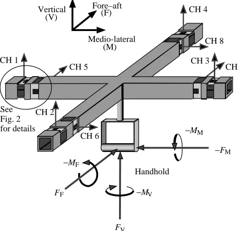
A single-element foil strain gauge (Micro-Measurements) was bonded to the surface of each cantilever (Heglund, 1981; Biewener and Full, 1992). The two gauges from each double-cantilever (top and bottom double-cantilevers) were wired into a Wheatstone half-bridge circuit. The other half of the circuit was completed within an external signal-conditioning module (National Instruments SCXI-1121). The radial configuration of these independent double-cantilevers allowed each end of the four arms to detect a horizontal load (in the plane of the transducer) and a vertical load (perpendicular to the plane of the transducer). Thus, eight channels of strain data are produced for a single load applied at the handhold (Fig. 1). The handhold was suspended from the center of the transducer with a reinforced shaft (3.81 cm in length) consisting of a tubular collar surrounding a quarter-inch threaded rod. The threaded rod was used to compress the collar, which provided a robust support of minimal mass.
The entire transducer was mounted beneath an aluminum baseplate (53.34 cm×53.34 cm×0.95 cm) using thin aluminum support blades located at the ends of each transducer arm (Fig. 2). The side of each support blade was milled to approximately the thickness of the cantilevered sensor beams. This flexible support blade allowed the orthogonal arms of the
transducer to resist the applied load in that orientation. This arrangement provided the maximum sensitivity for horizontal loads (Fig. 2). A perfectly rigid support for each arm of the transducer would restrict the deflection of the transducing elements on the orthogonal arms.
The fundamental resonant frequencies of the transducer for the vertical, fore–aft and medio-lateral directions were 170 Hz, 85 Hz and 65 Hz, respectively. These frequencies were excited by hammer impacts to the handhold in line with the three axes of orientation. The difference between the latter two frequencies presumably represents the stray sensitivity of compliance for the machined metal thickness.
Brachiation runway
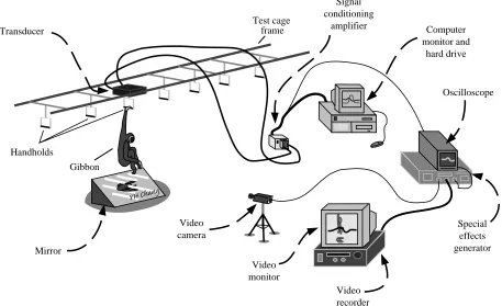
To provide a rigid mounting surface for the transducer, the frame of the test cage to which it mounted was solidly reinforced against the sides of the concrete walls and ceiling of a room using a series of posts and autojacks. The test arrangement and acquisition equipment are shown in Fig. 3. Although only a single transducer was used, it was assumed that the action of each limb was symmetrical. This assumption was verified by comparing records from different runs in which alternate hands were used for support on the transducer handhold.
The handhold of the transducer and six identical uninstrumented handholds were made from 3.8 cm o.d. aluminum tubing (0.3 cm thick). Handholds were suspended rigidly from the ceiling of the test enclosure in line with each other and positioned at the same height. A plastic tarpaulin camouflaged the transducer apparatus among the uninstrumented handholds. The transducer was positioned as the fourth handhold of the series. The test subject was an adult, female, white-handed gibbon (Hylobates lar Chivers, 7.95 kg, 11 years of age).
Vertical Fore–aft
Medio-lateral
CH 1
CH 2
CH 3 CH 4
CH 5 CH 7
CH 8
CH 6 See
Fig. 2 for details
(V) (F)
(M)
−MM
−FM
−MV
−MF
F
F
FV
Handhold
Fig. 1. The superstratum force transducer showing milled sensor cantilevers with attached foil strain gauges. For an applied load at the handhold, the transducing element at the distal end of each arm is able to detect one vertical and one horizontal load depending on the orientation of the sensor cantilevers for a total of eight acquisition channels (CH 1–8). The calibration matrix is able to convert these eight loads into calibrated forces (F) in the three orthogonal axes (medio-lateral, fore–aft and vertical, indicated by subscripts M, F and V, respectively) and moments (M) about those axes.
Same thickness Support blade
[image:2.609.44.291.74.312.2]Gauges Baseplate
[image:2.609.306.560.74.220.2]Data acquisition system
Strain data from each of the sensors were acquired using virtual instrumentation software (programmed in LabView 3.1.1). Eight channels of data were multiplexed at 4 kHz (or 500 Hz per channel). The analog data were amplified (National Instruments SCXI-1000 and SCXI-1121 modules), converted to digital format (National Instruments NB-MIO-16L) and stored on microcomputer (Power Macintosh 7100/80AV).
A single video camera (Digital 5000 Panasonic) was used to capture a kinematic record of the brachiation event (60 Hz framing rate shuttered to 1/500 s exposure time). A 1.8 m×1.2 m mirror was placed below the transducer (at approximately 45 ° to the floor) and positioned to give a view of the animal from beneath as it swung past the transducer. This allowed simultaneous recording of lateral and inferior views with a single video camera. One of the vertical transducer channels was spliced from the amplifier output and sent to an oscilloscope (Tektronics 135J). A second video camera recorded an image of this trace and this was superimposed over the image of the animal using a special-effects generator (Panasonic WJ4600C). This allowed synchronization of the force transducer output and video recordings.
Calibration of transducer
Calibration of the six degrees of freedom of the transducer required the application of six known, independent, static loads
to the transducer, which were then recorded for later analysis. These six known loads were applied individually at the center of the transducer handhold using an arrangement of pulleys and masses to produce a matrix of applied loads (load matrix, L6×6;
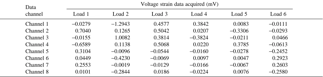
Table 1). The amplified voltage output from the transducer for each static load applied was averaged over the period of acquisition and tabulated (Table 2). The eight channels of voltage data acquired as a result of these applied loads can be represented by the strain matrix (S8×6). Since the eight
transducer elements responded linearly to the loads applied, these matrices (L6×6and S8×6) fit the following equation:
[S8×6] = [I8×6] · [L6×6] , (1)
where [I8×6] is an 8×6 influence matrix. Given L and S, I is
easily found. Calculation of the six possible applied loads at the handhold from acquired strain readings, however, required the use of a ‘conversion’ matrix [C6×8] (assumed constant),
where:
[L6×1] = [C6×8] · [S8×1] , (2)
at each sampling of the transducer.
We take [C] to be the pseudo-inverse of [I] so that:
[C6×8] = [I8×6]−1 = {[S8×6] · [L6×6]−1}−1, (3)
where [L]−1 is a proper inverse, but the other inverses are
pseudo-inverses. We found the pseudo-inverse using a simple MATLAB command.
Mirror Transducer
Video camera
Video monitor
Video recorder
Oscilloscope
Special effects generator Computer monitor and
hard drive Signal
conditioning amplifier Test cage
frame
Handholds
[image:3.609.78.535.76.355.2]Gibbon
Since the transducer produces eight strain signals to measure only six load components (FM, FF, FV, MM, MFand MV), some
of the data are redundant. Using the pseudo-inverse allows us to achieve greater accuracy than would be possible by discarding two channels. This procedure also eliminates all crosstalk between signals.
Data analysis
The voltage strain data were analyzed for noise using a software-based spectral analysis program (programmed in LabView 3.1.1). Noise peaks at 60 Hz and 180 Hz were filtered using Butterworth bandstop filters. In addition, a Butterworth low-pass filter was used to filter noise above 50 Hz. The conversion procedure (equation 3) was used to convert the eight channels of strain data to six force (F) and moment (M) reaction components applied at the handhold in three orthogonal axes (FM, FF, FV, MM, MF, MV, where the subscript
M is medio-lateral, F is fore–aft direction of travel, and V is vertical).
Determining the movements of the center of mass
Movements of the center of mass were determined from force data after cancelling for static gravitational load. Contact reaction force at the handhold determines the acceleration of the center of mass (CM). Integration of CM acceleration determines velocity transitions during contact, and integration of velocity transitions determines CM positional changes. Integration constants were determined in a manner similar to
Cavagna et al. (1977). Because the animal was moving along a level superstratum, it was assumed that the gibbon’s mean velocity in the vertical direction was zero for a complete stride. The integration constant for the fore–aft velocity was taken to be the mean forward speed of the gibbon, calculated by measuring the speed directly from the video record of a complete stride cycle. The crown of the gibbon’s head (which does not move noticeably with respect to the trunk of the body) was used as a recognizable point from which the distance traveled over one complete stride was measured. Measurements were taken from the hand release of a given hand to the following release of the same hand divided by the time interval for that stride. The video image was calibrated using the known position of the handholds, and measurements were made using a digitization program (NIH Image version 1.57).
The vertical position constant was estimated as 0.84 m from the handhold when the center of mass reached its minimum vertical position (mid-support). This value was determined by previously reported procedures (Prueschoft and Demes, 1984). During mid-support, we idealized the support limb as one cylinder and the rest of the body and limbs as a second cylinder (the dimensions of these cylinders follow Prueschoft and Demes, 1984). In all brachiation recordings studied by us, the support limb was observed to be in full extension at mid-support. Thus, it was assumed that at mid-support the center of mass was 0.84 m below the handhold.
[image:4.609.43.567.86.190.2]The fore–aft position constant was estimated such that the Table 1. Load matrix (L6x6) applied to the transducer for calibration
Reaction component Loads applied
at handhold Load 1 Load 2 Load 3 Load 4 Load 5 Load 6
FM(N) −123.998 0 0 0 0 0
FF(N) 0 198.947 0 0 0 0
FV(N) 0 0 198.947 0 0 0
MM(N m) 0 0 0 −22.762 0 0
MF(N m) 0 0 0 0 −20.233 0
MV(N m) 0 0 0 0 0 −22.762
Calibration depends on the application of six different, known loads.
FM, FF, FV, forces applied in the medio-lateral (M), vertical (V) or fore–aft (F) directions, respectively; MM, MF, MV, moments applied in the medio-lateral, vertical or fore–aft directions, respectively.
Table 2. Strain matrix (S8x6) acquired from the transducer during calibration using the loads described in Table 1
Data Voltage strain data acquired (mV)
channel Load 1 Load 2 Load 3 Load 4 Load 5 Load 6
Channel 1 −0.0279 −1.2943 0.4577 0.3842 0.0083 −0.0111
Channel 2 0.7040 0.1265 0.5042 0.0207 −0.3306 −0.0293
Channel 3 −0.0155 1.0082 0.3814 −0.3824 −0.0211 0.0466
Channel 4 −0.6589 0.1138 0.5068 0.0220 0.3785 −0.0613
Channel 5 0.3104 −0.0096 −0.0544 −0.0160 −0.0278 −0.2452
Channel 6 0.0449 −0.4230 −0.0069 0.0097 0.0047 0.2923
Channel 7 0.2553 −0.0019 −0.0129 −0.0166 −0.0067 0.2603
[image:4.609.43.561.618.742.2]gibbon’s center of mass was directly beneath the handhold at mid-support (i.e. fore–aft position equal to zero).
Results
Verification of the acquisition and analysis system using a simple pendulum
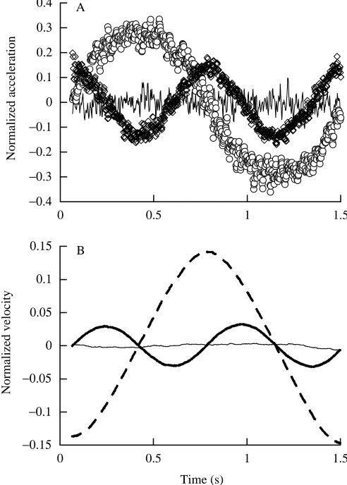
The accuracy of the transducer, the equipment and the analysis procedures can be tested by measuring the passive swinging of a simple pendulum (see Blickhan and Full, 1992). A cylindrical pendulum (6.30 kg, 0.27 m long) was swung from the transducer handhold by a 0.37 m cord. The pendulum was video-recorded swinging through a 44.3 ° arc in the fore–aft direction as the transducer measured the forces and torques at the handhold. Fig. 4 shows the acceleration (Fig. 4A) and velocity (Fig. 4B) calculated for the CM (three oreientations represented) for one cycle of oscillation. Fig. 5 depicts the corresponding mechanical energy of the pendulum during this cycle. The acceleration components are plotted normalized to gravity (g=9.81 m s−2). The velocity components are plotted
normalized to gravity and length l, where l is the distance of the pendulum’s center of mass from the handhold (0.505 m). The pendulum was composed of a cylindrical weight suspended from a light cord. Length l was calculated as cord length plus half of pendulum length. The energy is plotted normalized to mass, gravity and l in Fig. 5. The acceleration data agree with expectations for a passive mass swinging along a pendular arc. We compared the transducer measurements with the calculated expectations using a numerical simulation program (Working Model). The results of this simulation are plotted in Fig. 5 for comparison.
Reaction forces
A typical data set for a slowly brachiating gibbon (exhibiting a dual support phase and moving at a mean forward speed of
Fig. 4. (A) Raw, unfiltered acceleration data for each of the three axes from a physical pendulum attached to the transducer handhold. These data are from the pendulum swinging through one complete cycle (which begins with the pendulum swinging through the center position moving in the negative fore–aft direction). Accelerations are normalized for the acceleration due to gravity. The noise (variability) indicated in this plot is indicative of this instrument. Note that a similar level of noise exists in records from the brachiating gibbon, but the magnitude of acceleration of this passive pendulum was much less than that of the gibbon; therefore, the signal-to-noise ratio is substantially greater for the brachiation analysis. Open circles represent the horizontal component in the direction of swing (fore–aft), open diamonds represent the vertical component and the solid line represents the horizontal component perpendicular to the direction of swing (medio-lateral). (B) Velocity of the pendulum from A determined via integration of acceleration in each orientation (bold solid line, vertical; dashed line, horizontal fore–aft; thin line, horizontal medio-lateral). These data are normalized for gravitational acceleration and l, the distance of the pendulum’s center of mass from the handhold (cord length plus half pendulum length, l=0.505 m). Note that the integration constants are chosen so that vertical velocity is 0 at both the top and bottom of the swing, while horizontal velocity is 0 at the top of each swing. The data were low-pass-filtered at 50 Hz, and notch-filtered at 60 and 180 Hz. However, the majority of smoothing comes from the integration process.
−0.4 −0.3 −0.2 −0.1 0 0.1 0.2 0.3 0.4
0 0.5 1 1.5
Normalized acceleration
A
−0.15 −0.1 −0.05 0 0.05 0.1 0.15
0 0.5 1 1.5
Normalized velocity
[image:5.609.49.295.115.459.2]Time (s) B
Fig. 5. Mechanical energy (normalized for weight, 61.8 N, and l, the distance of the pendulum’s center of mass from the handhold, 0.505 m) of a physical pendulum and a numerical simulation swinging through a complete cycle in the fore–aft direction. Note that the gravitational potential energy of the physical pendulum (solid line) and the translational kinetic energy of the physical pendulum (dashed line) are out of phase. Gravitational potential energy (open squares) and kinetic energy (filled squares) for the numerical simulation are plotted for comparison with the observed data.
−0.02 0 0.02 0.04 0.06 0.08 0.1
0 0.5 1 1.5
Normalized energy
[image:5.609.318.565.472.633.2]−2 −1 0 1 2 3
0 0.5 1 1.5 2 2.5 3
Reaction force/body weight
Time (s)
t1 t2 t3 t4
A
−3 −2 −1 0 1 2 3
0 0.25 0.5 0.75 1 1.25 1.5
Velocity (m s
−
1)
Time (s) Single support
Dual
support Dual support
B
−1.2 −0.8 −0.4 0
−0.8 −0.4 0 0.4 0.8
Position of handhold (estimated from video)
Up
Direction of travel
Vertical position (m)
[image:6.609.245.556.64.734.2]Fore–aft position (m) C
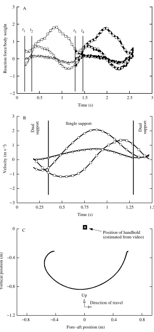
0.8 m s−1) is shown in Fig. 6. The gibbon’s force reaction
components (Fig. 6A) are similar to the ground reaction forces observed for terrestrial locomotion (see, for instance, Biewener and Full, 1992) with one notable exception: the fore–aft force vector. While the vertical force trace shows a characteristic peak at mid-support (similar to that seen in terrestrial locomotion), the fore–aft force of the center of mass increases (accelerates) in the direction of travel before mid-support and decreases (decelerates) after mid-support. In contrast, terrestrial locomotion dictates that the walking or running animal decelerate until mid-support (heel strike to mid-stance) and then accelerate after mid-support (mid-stance to toe-off). The peak absolute medio-lateral force was found to be 15.6 % of the peak vertical force.
The forward (fore–aft) velocity increases until mid-support, after which it decreases (Fig. 6B). Vertical speed reaches maximum absolute values twice during limb support, a negative value when the center of mass is falling and a positive value when the center of mass is rising. The path that the gibbon’s center of mass travels in the sagittal plane is shown in Fig. 6C and is in the form of an arc about the fixed handhold. At this speed, the CM actually moves backwards during the initial, dual-support portion of the swing. This was verified from video recording and is due to the simultaneous flexion of the previous support limb with extension of the succeeding support limb. This movement allows the animal to begin the support phase of the stride with its support arm in full extension. We suspect that this motion was used to adjust arm extension for handholds that were placed closer together than optimal for this animal.
Potential and kinetic energy
Calculations of potential and kinetic energy changes of the centre of mass over the course of a half-stride (single limb contact) can be made using velocity and positional information
derived from the transducer output (Fig. 7). At this speed (0.8 m s−1), kinetic and potential energy are 180 ° out of phase.
This is the pattern shown by a pendulum and indicates that the gibbon can exchange kinetic and gravitational potential energy to reduce the cost of locomotion.
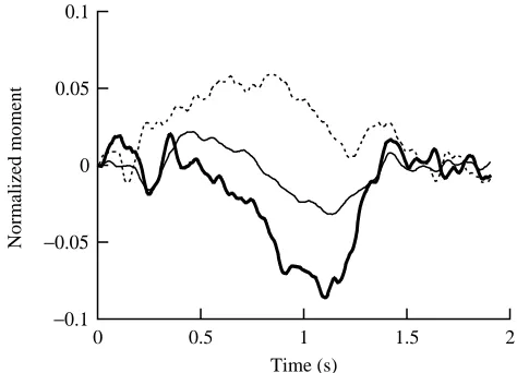
Reaction moments
The corresponding moment reaction data for the gibbon moving at 0.8 m s−1 are shown in Fig. 8. In describing the
reaction moments, we refer to the moment relative to the axis about which it acts. If the gibbon contacts the handhold with its right hand, a positive reaction moment in the vertical axis indicates pronation of the animal’s right pectoral limb. As can be seen in Fig. 8, there is a tendency for pronation of the pectoral limb throughout the first half of this half-stride followed by a period of supination (indicated by a negative vertical reaction moment). The medio-lateral reaction moment was largely negative throughout hand contact, indicating that this reaction moment was primarily due to the shear forces of the gibbon’s grip as it rotated its body around the handhold in the sagittal plane. The fore–aft reaction moment was seen to follow the lateral movement of the gibbon’s center of mass.
Discussion
[image:7.609.321.558.452.623.2]The system described here for measuring and analyzing kinetics is able to resolve six independent reaction components at a handhold applied by a brachiating gibbon. The reaction forces and moments applied by the gibbon at the instrumented handhold have characteristics similar to terrestrial force
Fig. 7. Gravitational potential energy (thin line), translational kinetic energy (sum of vertical and horizontal kinetic energy; thick line) and the sum of potential and kinetic energies (dashed line) shown over the course of a half-stride in slow brachiation. Note that the gravitational potential energy and translational kinetic energy are out of phase (as was seen for a pendulum in Fig. 5).
0 10 20 30 40 50
0 0.25 0.5 0.75 1 1.25 1.5
Energy (J)
Time (s)
Fig. 8. Normalized reaction moments for a half-stride of slow brachiation (0.8 m s−1) along horizontally oriented handholds (see Fig. 3). The moment around the axis in the direction of travel (fore–aft axis) is shown by the thin solid line, the moment around the axis perpendicular to travel (medio-lateral axis) is shown by the dashed line, and the moment around the vertical axis is shown by the thick solid line. The data were low-pass-filtered at 50 Hz. Measured moments are normalized by mgl, where m is mass (7.95 kg), g is gravitational acceleration (9.8 m s−2) and l is 0.84 m (the ‘characteristic’ length determined for this animal).
−0.1 −0.05 0 0.05 0.1
0 0.5 1 1.5 2
Normalized moment
[image:7.609.53.296.504.667.2]platform traces. The vertical ground reaction force has a peak near mid-support. The fore–aft force component has the sinusoidal shape also characteristic of terrestrial locomotion with one very notable distinction: in brachiation, the animal accelerates its center of mass in the forward direction during the early half of the swing and decelerates during the latter half of the swing. This is in direct contrast to terrestrial locomotion, where deceleration occurs before mid-stance and acceleration occurs after mid-stance. This reversal of fore–aft accelerations follows the expected dynamics for an animal swinging beneath its supporting medium; that is to say, it demonstrates the kinetic difference between a pendulum and an inverted pendulum. Further analysis of the mechanical energetics of brachiation using transducers of the type described here should reveal aspects of motion and control during brachiation that have not previously been identified. Additionally, as in terrestrial gait analyses, these kinetic data can be combined with kinematic and electromyographic data to estimate joint moments and muscle forces in the pectoral limbs during brachiation and other suspensory behaviors.
For decades, quantifying the force and torque interactions between an animal and its stratum have been essential for providing information about the dynamics of terrestrial locomotion. Such an approach has been absent from brachiation research. Applying a similar technique to understanding the dynamics of brachiation promises to lead to a more complete understanding of brachiation, since brachiation is simply a highly specialized mode of limbed locomotion within the gravitational environment. A thorough understanding of brachiation will probably aid in the development of a more complete understanding of all limbed locomotion, just as the analysis of other highly specialized locomotory modes, such as hopping in kangaroos (Dawson and Taylor, 1973) and kangaroo rats (Biewener et al. 1981), has provided insight into the mechanisms functioning in the limbs of many other animals (Alexander, 1988; Taylor, 1994). Understanding the mechanisms that drive the gibbon’s locomotory system may reveal features common to all other forms of limbed locomotion.
We would like to thank Susan G. Larson, Jack Stern, Brigitte Demes, Marianne Crisci, Roshna Wunderlich and Brian Richmond of the Department of Anatomical Sciences, State University of New York at Stony Brook, for much assistance. The animal and facilities were provided courtesy of the Department of Anatomical Sciences, State University of New York at Stony Brook (supported by NSF SBR 9507078 to Susan G. Larson). Additionally, we thank Anthony Farquhar, Jeff Koechling, Dennis Cullinane, Susan Dawson and William Schutt. This work was supported by NSF SBR 9422118 to J.E.A.B. and by Sigma Xi Grants-in-Aid of Research to Y.H.C.
References
ALEXANDER, R. MCN. (1988). Elastic Mechanisms in Animal
Movement. Cambridge: Cambridge University Press.
ALEXANDER, R. MCN. ANDJAYES, A. S. (1980). Fourier analysis of forces exerted in walking and running. J. Biomech. 13, 383–390. AVIS, V. (1962). Brachiation: the crucial issue for man’s ancestry.
Southw. J. Anthropol. 18, 119–148.
BIEWENER, A. A., ALEXANDER, R. MCN. ANDHEGLUND, N. C. (1981). Elastic energy storage in the hopping of kangaroo rats (Dipodomys spectabilis). J. Zool., Lond. 195, 369–383.
BIEWENER, A. A. AND FULL, R. J. (1992). Force platform and kinematic analysis. In Biomechanics – Structures and Systems (ed. A. A. Biewener), pp. 45–75. New York: Oxford University Press.
BLICKHAN, R. ANDFULL, R. J. (1992). Mechanical work in terrestrial locomotion. In Biomechanics – Structures and Systems (ed. A. A. Biewener), pp. 75–96. New York: Oxford University Press. CARPENTER, C. R. (1976). Suspensory behavior of gibbons Hylobates
lar: a photoessay. In Gibbon and Siamang, vol. 4 (ed. D. M. Rumbaugh), pp. 1–20. Basel: Karger.
CAVAGNA, G. A. (1975). Force plates as ergometers. J. appl. Physiol.
39, 174–179.
CAVAGNA, G. A., HEGLUND, N. C. AND TAYLOR, C. R. (1977). Mechanical work in terrestrial locomotion, two basic mechanisms for minimizing energy expenditure. Am. J. Physiol. 233, R243–R261.
DAWSON, T. J. ANDTAYLOR, C. R. (1973). Energy cost of locomotion by kangaroos. Nature 246, 313–314.
FLEAGLE, J. G. (1974). The dynamics of a brachiating siamang (Hylobates [Symphalangus] syndactylus). Nature 248, 259–260. HEGLUND, N. C. (1981). A simple design for a force-plate to measure
ground reaction forces. J. exp. Biol. 93, 333–338.
HOLLIHN, U. (1984). Bimanual suspensory behavior: morphology, selective advantages and phylogeny. In The Lesser Apes: Evolutionary and Behavioral Biology (ed. H. Preuschoft, D. J. Chivers, W. Y. Brockelman and N. Creel), pp. 85–95. Edinburgh: Edinburgh University Press.
MCMAHON, T. A. (1984). Muscles, Reflexes and Locomotion, pp. 189–233. Princeton: Princeton University Press.
PARSONS, P. E. ANDTAYLOR, C. R. (1977). Energetics of brachiation versus walking: a comparison of a suspended and an inverted pendulum mechanism. Physiol. Zool. 50, 182–188.
PAUL, J. P. (1966). Forces transmitted by joints in the human body.
Proc. Inst. mech. Eng. 18, 8–15.
PREUSCHOFT, H. ANDDEMES, B. (1984). Biomechanics of brachiation. In The Lesser Apes: Evolutionary and Behavioral Biology (ed. H. Preuschoft, D. J. Chivers, W. Y. Brockelman and N. Creel), pp. 96–118. Edinburgh: Edinburgh University Press.
SWARTZ, S. M. (1993). Biomechanics of primate limbs. In Postcranial
Adaptation in Nonhuman Primates (ed. D. C. Gebo), pp. 19–42. Dekalb: N. Illinois University Press.
TAKAHASHI, L. K. (1990). Morphological basis of arm-swinging: multivariate analysis of the forelimbs of Hylobates and Ateles. Folia primatol. 54, 70–85.
TAYLOR, C. R. (1994). Relating mechanics and energetics during exercise. In Comparative Vertebrate Exercise Physiology: Unifying Physiological Principles (ed. J. H. Jones). Adv. vet. Sci. comp. Med. 38A, 181–215. New York: Academic Press.
WINTER, D. A. (1990). Biomechanics and Motor Control of Human
Movement, 2nd edition. New York: John Wiley & Sons.