Load Frequency Control of Area
Multi-Source Power System using Teaching Learning
Optimization Technique
Monika Arora1 Kapil Parkh2
1
M.tech Scholar, 2Assistant Professor Electrical Engineering SITE,Nathdwara
Abstract: Interconnecting two generating areas is very beneficial in respect of increased stability, lower generation cost, sharing of load, reducing congestion in transmission and a backup system. In present context too two area interconnected system is being considered. For stable operation it is required that the deviation in frequency and tie line power exchange should almost be zero. To ensure this in each of the system Automatic Generation Control (AGC) is implemented for Load frequency control (LFC) for each area. For this AGC continuously observe the difference in the amount of power i.e. demanded and actual power generated by the units. This difference is termed as Area Control Error which in turn is fed back to LFC loop so as to adjust the generation of units as according to the power demanded. In the present case each area consists of three different power generation sources namely thermal, hydro and gas. Hence, it is a multi unit power source system and it is necessary to coordinate the LFC of each source efficiently in both the areas. To further improvise the performance of LFC loop Proportional Integral Derivative (PID) Controller is included in it, to which ACE act as the input. To give the optimal output from PID controller it was optimized using a new technique Teaching Learning Based Optimization (TLBO).
The given two area system is analysed with two different cases i.e. with AC tie line and then with AC tie line in parallel with HVDC parallel link. To verify the effectiveness of present scheme it was examined and compared with the system employing newly published optimal output feedback controller with DE Algorithm. It was tested with different performance measures such as settling time and standard error criteria of frequency and tie-line power deviation causing a step load perturbation (SLP). It was observed that with the TLBO tuned PID the given system dynamic performance is better and its designed system is tough not affected by variation in loading conditions, system parameters or size of SLP.
Keywords: Automatic Generation Control; TLBO; Load Frequency Control;AC Tie Line;AC-DC Tie Line
I. INTRODUCTION
A. Introduction
Power system is requiring operating stable and maintaining frequency all condition at different types of load. The load frequency control is a best method to achieve this condition. The load frequency control is used for controlling the real power and frequency. It consists of two loop first is primary loop and second secondary loop. We achieve many objectives by Automatic Generation Control(AGC) as maintain frequency, generation as required system and maintain power exchanges through tie lines[5].
The load frequency control applies single area system and also multi area system. Past year load frequency control implemented without controller and optimization technique. Today we apply modern control technique of load frequency control. Modern technique maintains frequency when any change of load. To achieve this many controller such as PI, PID controller and many optimization technique as particle swarm optimization technique, genetic algorithm, fuzzy logic controller, artificial neural network, differential evolution etc. are used.
Since the last few years Teaching learning based optimization(TLBO) is preferred by researchers for optimization problems Teaching learning based optimization(TLBO) offers many advantages over differential evolution like simple algorithm can be easily implemented and it uses few parameters[3].
B. Objective Function
The aim of this work is to use genetic algorithm to obtain the optimal PID controller parameters for a two-area system. Any adjustment of the regulator represents a particle in the search space, the proportionality of its parameters, Kp, Ki and Kd changes in
order to minimize the error function (objective function in this case). The error function used here is the integral time of the absolute errors (ITAE), Integral. The equation are
=∫ (| |). . (1) Hence the design problem of PID controller is stated as
Minimize J subjected to
≤ ≤ , ≤ ≤ , ≤ ≤ (2)
II. SYSTEMMODEL
A. AGC in a Multi Area System
In a nonstop (multi-extend) framework there for each control region of an ALFC loop (situated in the EDC of this range). They are appeared in fig.1 for the related working framework. For an aggregate change in the load demand of ∆PD the steady state frequency
deviation is given in both zones by means of
2 1 2 1
P
Dw
w
f
(3) Where)
/
1
(
1 1 1
D
R
and
2
(
D
2
1
/
R
2)
Fig.1 AGC for A Multi-Area Operation with AC-DC Parallel Tie Line..
two stations. One of the significant applications of HVDC transmission is to maneuver a DC link in parallel with an AC link interconnecting two control areas to get an enhanced system performance with better stability under small system disturbances.The system has been tested for these two particular cases with small load perturbation (SLP) in respect of settling time and frequency deviation.
B. Expression For Tie-Line Flow In A Two-Area Interconnected System
Consider an adjustment in load ∆PD1 in area-1. The unfaltering state frequency deviation ∆f is the same for both the areas. That is ∆f
= ∆f1 = ∆f2. In this way, for area-1, we have
∆Pm1 - ∆PD1 - ∆P12 = D1∆f (4)
Where, ∆P12 is the tie line power flow from area1to area2 and for area2
∆Pm2 + ∆P12 = D2∆f (5)
The mechanical power depends on regulation. Hence ∆P =−∆ and ∆P =−∆
Substituting these equations, yields
( + D )∆f =−∆P − ∆P and ( + D )∆f =∆P (6)
Solving for ∆f, we get
∆f = ∆
( )=
∆
(7)
and ∆P = ∆ (8)
Where β and β are the characteristic composite of area1 or area-2 of frequency response respectively. An increase in the load of area1 ∆PD1(change in load demand of area1) results in a reduction of the frequency in the two zones and a tie line flow of ∆P12. A
positive ∆P12 (change in tie line power) indicates the flow from zone-1 to zone-2, while a negative ∆P12, a flow from zone-2 to the zone-1. Similar ∆PD2 change in load area-2, then change in frequency due to change in load demand of area-2 are
∆f = ∆ (9)
And
∆P =∆P = ∆ (10)
III. TLBO TUNED PID CONTROLLER
A. Teaching Learning Optimization Technique
TLBO is the new kind of optimization algorithm for getting the more optimal operation of the problems, which have been previously, solved using other techniques. It is a very simple concept containing two important parts, one is a Teaching and other is learning.
It simulates the exact environment of a class room where a teacher is imparting knowledge to the students (learner). This is one way of learning as teacher knowledge is always more than the students. Then comes the second way, after teacher left the class room students start discussing the topic taught. Students will share with each their parts understanding of the topic that means interaction among them.
TLBO algorithm follows the same basic concept to find out the best possible solution in two parts,
1) Teacher (best solution) to students (learners)
2) Interaction among learners. M(i)=mean
T(i)=teacher (best solution point)
Now T(i) will always works to move M(i) close to the value which it has. Therefore, now mean changes to Mnew. The new solution will be the difference of old and new mean.
Mean(i) = r(i) [Mnew TF×M(i)] (11)
r(i)=random no. (0 to 1)
TF =teaching factor ( 1 or 2 random selection). TF is responsible for the mean value change. Therefore, new solution is,
This is one part of learning directly via teacher. In other part learner learns via interaction among them. Learner learns from another learner only if the other has more knowledge. This update is given as,
I= no. of iteration For I = 1:Pn
Xi and Xj selected randomly I is not equal to j
If f (Xi) < f (Xj) Xnew(i) = Xold(i) + ri(Xi − Xj) (13)
Else Xnew(i) = Xold(i) + ri(Xj − Xi) (14)
Accept Xnew if it gives a better function value. Algorithm,
Fig.2 shows TLBO algorithm diagram.
a) Statement of problem which is to be optimized. Initialization of parameters of it Size of population =Pn
Generation number= Gn
No. of Design Variables= Dn its limit (UL, LL). Ex.
Minimize f (X). Subject to Xi ∈ xi = 1, 2. . . Dn
f (X) =objective function, X = vector for design variables ( LL ≤ x(i) ≤ UL) b) Starting P (Population).
Random generation of population depending on Pn and Dn. Here, Pn => learners
Dn => Subjects It is expressed as
P =
⎣ ⎢ ⎢
⎡ X , X, … . X , X , X , … . X ,
… . … . … . … . X , X , … . X , ⎦
⎥ ⎥ ⎤
c) Teacher phase.
Mean calculation P column wise giving mean of each subject. M,D = [m1,m2, . . . ,mD]
For a iteration best solution is, Xteaxher=Xf (X)=min
Teacher efforts is to move M, D to Xteacher. This the new mean for the iteration. Mean Difference (i)= r(i) [Mnew TF×M(i)]
r(i) = random number (0≤r(i)≤1)
TF= teacher factor (0 to 1) decide new mean value Then the new solution is,
Fig. 2: TLBO Algorithm lock Diagram
d) Learner phase. learners increase their knowledge with the help of their mutual interaction
e) Termination criterion.
The given iteration will stop when Pn=maximum, otherwise goes to step 3.
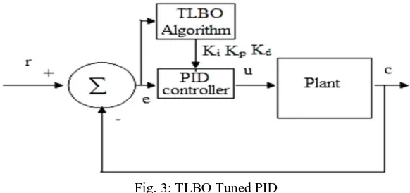
[image:5.612.160.451.511.648.2]B. TLBO Tuned PID controller
Fig. 3: TLBO Tuned PID
IV. RESULT AND DISCUSSIONS
This result presents a utility of the novel artificial intelligent search approach to discover the parameter optimization of load frequency control (LFC) considering proportional Integral Derivative Controller (PID) for a power system. A area multi-source power system comprising hydro, thermal with reheat turbine and gas turbine. The linearized models of governors, reheat turbines, hydro turbines, gas turbines are used for simulation and LFC study of the power system. The contrast of Teaching Learning based Optimization Algorithm (TLBO) and Differential Evolution (DE) is employed to look for optimum controller parameters to reduce the time domain objective feature. The overall performance of the proposed approach has been evaluated with two conditions as AC tie lines and AC-DC parallel tie lines. The system parameters optimized by two algorithms by means of contrast with the TLBO and DE algorithm, the effectiveness of the proposed TLBO are verified over different running situations, and device parameter variations.
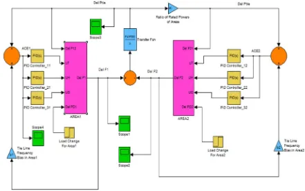
[image:6.612.84.525.420.697.2]A. Matlab/Simulink Implementation Of Block Diagram Of Two Area (Thermal-Hydro-Gas System With No Reheat Turbine) Load Frequency Control
Fig.4 shows a MATLAB/SIMULINK model of multi-area multi-source power system. Each area comprises reheat thermal, hydro and gas generating units. The system operated with two conditions as AC tie lines and AC-DC parallel tie lines. The R1, R2, R3 are
the regulation parameters of thermal, hydro and gas units respectively, UT, UH and UG are the control outputs for of thermal, hydro
and gas units respectively, KT, KH and KG are the participation factors of thermal, hydro and gas generating units, respectively, TSG
is speed governor time constant of thermal unit in sec, TT is steam turbine time constant in sec, Kr is the steam turbine reheat
constant, Tr is the steam turbine reheat time constant in sec, Tw is nominal starting time of water in penstock in sec, TRS is the hydro
turbine speed governor reset time in sec, TRH is hydro turbine speed governor transient droop time constant in sec, TGH is hydro
turbine speed governor main servo time constant in sec, XC is the lead time constant of gas turbine speed governor in sec, YC is the
lag time constant of gas turbine speed governor in sec, cg is the gas turbine valve positioner, bg is the gas turbine constant of valve
positioner, TF is the gas turbine fuel time constant in sec, TCR is the gas turbine combustion reaction time delay in sec TCD is the gas
turbine compressor discharge volume-time constant in sec, KPS power system gain in Hz/puMW, TPS is the power system time
constant in sec, ∆F is the incremental change in frequency and ∆PD incremental load change.
B. Result Of Tlbo Pid Optimization
[image:7.612.76.540.119.328.2]Table 1 & Table 2 shows optimized PID parameters with AC & AC-DC Tie line
Table 1: Optimized PID Parameter With AC Tie Only
S.No. Parameter DE Optimized PID Controller TLBO Optimized PID Controller
Thermal Hydro GAS Thermal Hydro GAS
ITAE .004474 0.0103
1 KP 0.779 0.5805 0.5023 4.5005 1.4059 1
2 KI 0.2762 0.2291 0.9529 1.0366 0.3261 9.9981
3 KD 0.6894 0.7079 0.6569 10 9.3309 1
Table 2: Optimized PID Parameter with AC-DC Tie Line Only
S.No. Parameter DE Optimized PID Controller TLBO Optimized PID Controller
Thermal Hydro GAS Thermal Hydro GAS
ITAE 0.1987 0.0143
1 KP 1.6929 1.77731 0.9094 9.7138 9.9381 1
2 KI 1.9923 0.7091 1.9425 1.3423 0.1212 9.8381
3 KD 0.8269 0.4355 0.2513 3.1984 1.000 1.0007
1) Case-1: 1% Step Load Change in Area1 with AC Tie Line & AC-DC Tie Line
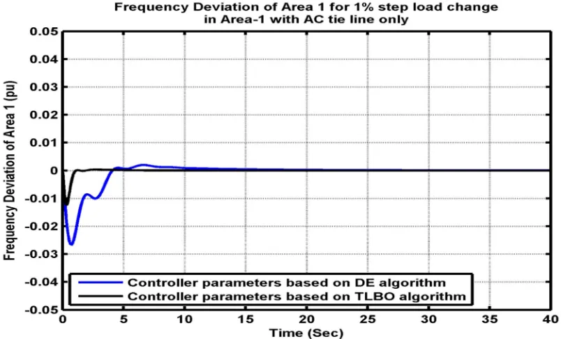
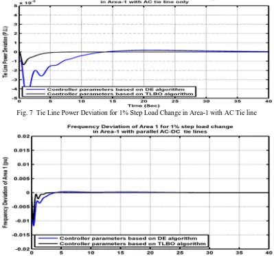
Fig. 5 to 10 shows frequency deviation of area-1, 2, tie line power deviation and changes in area control error of 1% step load change in area-1. To study the effective behavior of the system with TLBO optimized controllers, a 1% step load perturbation (SLP) is applied at t = 0 s. To show the dominance of the proposed approach, the results are compared with a newly published DE optimized controller for the same power system. It can be seen proposed TLBO optimized PID controller gives superior dynamic response having comparably smaller peak overshoot and lesser settling time as compared to the DE optimized PID controller. The designed controllers are emphatic and carry out the satisfactory operation when employs TLBO PID controller.
[image:7.612.111.513.443.686.2]Fig. 6 Frequency Deviation of Area-2 for 1% Step Load Change In Area-1 with AC Tie line
Fig. 7 Tie Line Power Deviation for 1% Step Load Change in Area-1 with AC Tie line
[image:8.612.107.506.341.715.2]Fig. 9 Frequency Deviation of Area-2 for 1% Step Load Change In Area-1 with AC-DC Tie Line
Fig. 10 Tie Line Power Deviation for 1% Step Load Change in Area-1 with AC-DC Tie Line
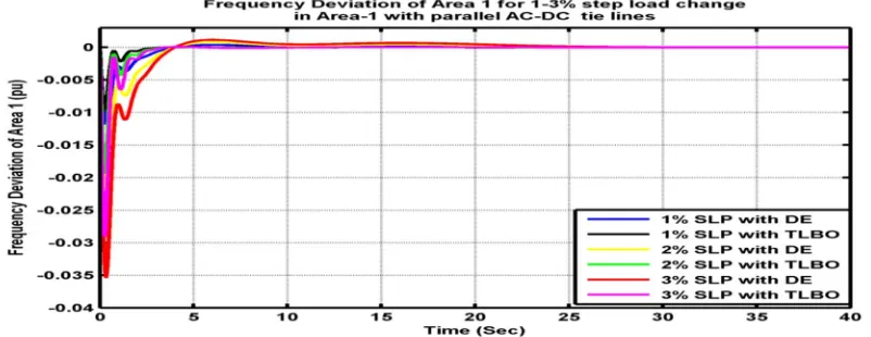
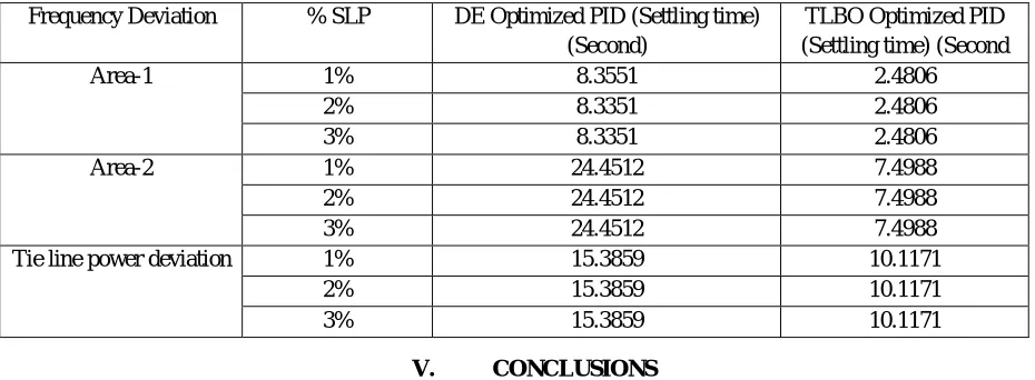
2) Case-2 : 1-3 % Step Load Change in Area-1 with AC-DC Tie Line
[image:9.612.112.504.267.433.2]Fig. 10 to 12 shows frequency deviation of area-1, 2, tie line power deviation and changes in area control error of 1% step load change in area-1. To study the effective behavior of the system with TLBO optimized controllers, a 1% step load perturbation (SLP) is applied at t = 0 s. To show the dominance of the proposed approach, the results are compared with a newly published DE optimized controller for the same power system. It can be seen that proposed TLBO optimized PID controller gives superior dynamic response having comparably smaller peak overshoot and lesser settling time as compared to the DE optimized PID controller. The designed controllers are emphatic and carry out the satisfactory operation when employs TLBO PID controller. . The comparison of different settling time both techniques are shown in table 3.
[image:9.612.107.508.563.718.2]Fig. 11. Frequency Deviation of Area-2 1-3% Step Load change in area-1 with AC-DC Tie Line
Fig. 12. Tie Line Power Deviation for 1-3% Step Load change in area-1 with AC-DC Tie Line
Table3 1-3% Step Load change in area-1 with AC-DC Tie Line Frequency Deviation % SLP DE Optimized PID (Settling time)
(Second)
TLBO Optimized PID (Settling time) (Second
Area-1 1% 8.3551 2.4806
2% 8.3351 2.4806
3% 8.3351 2.4806
Area-2 1% 24.4512 7.4988
2% 24.4512 7.4988
3% 24.4512 7.4988
Tie line power deviation 1% 15.3859 10.1171
2% 15.3859 10.1171
3% 15.3859 10.1171
V. CONCLUSIONS
[image:10.612.75.540.429.600.2]REFERENCES
[1] UR Bhatt, N Chouhan, R Upadhyay and C Agrawal, "ONU placement in fiber-wireless (FiWi) access networks using teacher phase of teaching learning based optimization (TLBO) algorithm." In Computational Intelligence & Communication Technology (CICT), 2017 3rd International Conference on, pp. 1-4. IEEE, 2017.
[2] H Haggi, SR Marjani and MA Golkar, "The effect of rescheduling power plants and optimal allocation of STATCOM in order to Improve power system static security using TLBO algorithm." In Electrical Engineering (ICEE), 2017 Iranian Conference on, pp. 1120-1125. IEEE, 2017.
[3] A Bhadoria, M Singh and M Gupta, "An improved elitism based teaching-learning optimization algorithm." In Electrical, Electronics, and Optimization Techniques (ICEEOT), International Conference on, pp. 3726-3730. IEEE, 2016.
[4] MK Debnath, NC Patel and RK Mallick, "Automatic generation control of a two area multi-unit interconnected power system with Proportional-Integral-Derivative controller with Filter (PIDF) optimized by TLBO algorithm." In Circuit, Power and Computing Technologies (ICCPCT), 2016 International Conference on, pp. 1-6. IEEE, 2016.
[5] S Kumari, G Shankar, S Gupta and K Kumari, “Study of Load Frequency Control by using Differential Evolution Algorithm”, International Conference on Power Electronics. Intelligent Control and Energy Systems, pp. 1-5, IEEE, 2016.
[6] A Malkhandi, “Teaching and Learning based Optimization Applied to Optimization of Power Transmission Line Parameters”, 6th International Conference on Power Systems (ICPS), pp. 1-4, IEEE, 2016.
[7] MM Puralachetty, VK Pamula, LM Gondela and VNB Akula, "Teaching-learning-based optimization with two-stage initialization." In Electrical, Electronics and Computer Science (SCEECS), 2016 IEEE Students' Conference on, pp. 1-5. IEEE, 2016.
[8] S Zheng and Z Ren, “Closed-Loop Teaching-Learning-Based Optimization Algorithm for Global Optimization”, 12th World Congress on Intelligent Control and Automation (WCICA), pp. 2120-2125, IEEE, 2016.
[9] XG Zhou, GJ Zhang, XH Hao, L Yu and DW Xu, "Differential evolution with multi-stage strategies for global optimization." In Evolutionary Computation (CEC), 2016 IEEE Congress on, pp. 2550-2557. IEEE, 2016.
[10]M Ebraheem and TR Jyothsna, “Comparative Performance Evaluation of Teaching Learning Based Optimization against Genetic Algorithm on Benchmark Functions”, Power, Communication and Information Technology Conference, pp. 327-333, IEEE, 2015.
[11]TK Pati, JR Nayak, BK Sahu and SK Kar, "Automatic generation control of multi-area thermal power system using TLBO algorithm optimized fuzzy-PID controller." In Circuit, Power and Computing Technologies (ICCPCT), 2015 International Conference on, pp. 1-6. IEEE, 2015.
[12] TK Pati, JR Nayak and BK Sahu, "Application of TLBO algorithm to study the performance of automatic generation control of a two-area multi-units interconnected power system." In Signal Processing, Informatics, Communication and Energy Systems (SPICES), 2015 IEEE International Conference on, pp. 1-5. IEEE, 2015.
[13] D Qu, S Liu, D Zhang, J Wang and C Gao, "Teaching-learning based optimization algorithm based on course by course improvement." In 2015 11th International Conference on Computational Intelligence and Security (CIS), pp. 48-52. IEEE, 2015.
[14] S Priyambada, PK Mohanty and BK Sahu, "Automatic voltage regulator using TLBO algorithm optimized PID controller." In Industrial and Information Systems (ICIIS), 2014 9th International Conference on, pp. 1-6. IEEE, 2014.