Abstract— Nose detection is an important part of a 3D face recognition process. Knowledge of the nose location will enable us to align an unknown 3D face with those in a face database. Besides that, the head pose can be deduced from information obtained from the nose. In this paper, a method is proposed to detect the nose tip from a three-dimensional face range image. This method identifies potential nose tip candidates by investigating the surrounding pixels. The nose tip is then identified from the potential candidates by their mean and variance values as well as their location which must be within the nose area. The proposed method has the ability to locate the nose tip without any manual input from the user, requires no training and is able to locate the nose tip for faces at different angles.
Index Terms—Nose area detection, Nose tip detection, 3D face.
I. INTRODUCTION
Face recognition using three dimensional (3D) images is becoming popular since it is not affected by a common problem of two dimensional (2D) face recognition systems, which is pose changes [1]. Calculating the surface distance between 2 face models is one of the 3D face recognition methods. This technique requires certain face feature points on one face to be identified and matched with the face feature points on the other face. This helps align the 2 faces together. An important face feature point is the nose tip. This is because the nose is the highest protruding point from the face. Besides that, it is not affected by facial expressions. Another important function of the nose is that it is able to indicate the head pose. Using 2D images, past works have included using luminance values to locate the nose tip [2]. This was achieved because the nose tip has a lower luminance value compared to other parts of the face. Besides that, the nostrils are considered as valley regions in a curvature map. However, this method would only work if the face was at a frontal position and looking straight into the camera. Tilted heads and non-frontal faces may cause error in nose detection since the nose tip luminance value might change or the nostrils
Manuscript received October 30, 2008.
Wei Jen Chew is with The University of Nottingham, Malaysia Campus, Jalan Broga, 43500 Semenyih, Selangor Darul Ehsan, Malaysia (phone: +603-8924 8358; fax: +603-8924 8017; e-mail: [email protected]).
Kah Phooi Seng is with The University of Nottingham, Malaysia Campus, Jalan Broga, 43500 Semenyih, Selangor Darul Ehsan, Malaysia (e-mail: [email protected]).
Li-Minn Ang is with The University of Nottingham, Malaysia Campus, Jalan Broga, 43500 Semenyih, Selangor Darul Ehsan, Malaysia (e-mail: [email protected]).
cannot be detected. Other 2D works include training the computer to detect the nose using Support Vector Machine (SVM) [3] or by using contrast values and edge detection to locate the nose [4]. The drawbacks are SVM has high computational complexity, thus a slow training time while the contrast and edge detection method is affected by expression changes.
Using 3D images, one of the methods used was to take horizontal slices of the face and then draw triangles on the slices [5]. The point with the maximum altitude triangle will be considered the nose tip. This method will work for frontal and non-frontal faces. However, for faces tilted to the top, bottom, left or right, errors can occur. This is because in these conditions, the nose tip on the horizontal slices will not be the maximum protruding point.
Another method to locate the nose tip from 3D images was used by Xu et al. [6]. To locate the nose tip, this method calculates the neighbouring effective energy of each pixel to locate suitable nose candidates. It then calculates the neighbouring mean and variance of each pixel and then uses SVM to further narrow down the nose tip candidates. Finally, the nose tip is found by choosing the area which has the top three densest nose candidate region. This method is able to locate nose tip from both frontal and non-frontal faces as well as tilted faces. However, it requires SVM [3] which has high computational complexity.
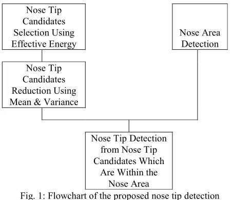
In this paper, we propose a method that is able to robustly detect the nose tip for various head poses and tilt but does not require the SVM [3] training. This method consists of evaluating the effective energy of the neighbouring pixels as well as calculating the mean and variance of the effective energy of each neighbouring pixel. Potential nose tip candidates are chosen based on each pixel’s effective energy, mean and variance values. Finally, the top 3 nose tip candidate with the densest amount of neighbouring nose tip candidates and is in the nose area is chosen as the nose tip. This proposed method eliminates the need for training and is a fully automatic system. Therefore, this becomes a suitable technique to be implemented in an automatic 3D face recognition system which usually detects the nose tip manually. Fig. 1 shows the steps for the proposed method.
This paper is organized into the following sections. Section II discusses about the nose tip candidates detection using effective energy, mean and variance values while Section III discusses about the nose area detection which is between the eyes and mouth area. Section IV discusses about the nose tip detection from nose tip candidates and Section V shows the results obtained and discussions about the results. Finally, Section VI concludes the paper.
Nose Tip Detection on a Three-Dimensional
Face Range Image Invariant to Head Pose
Nose Tip Candidates Selection Using Effective Energy Nose Area Detection Nose Tip Candidates Reduction Using
Mean & Variance
Nose Tip Detection
from Nose Tip Candidates Which
[image:2.612.72.300.44.239.2]Are Within the Nose Area
Fig. 1: Flowchart of the proposed nose tip detection method.
II. NOSE TIP CANDIDATES DETECTION
Potential nose tip candidates are detected based on the position of their neighbouring pixels. Since the nose tip is a protruding area, this means that all its neighbors should be at a lower height in the protruding direction. Using (1) from Xu et al. [6], the effective energy of each neighbouring pixels of each pixel is calculated.
Effective Energy = ||Pi – P|| cos θ
(1) where P is the pixel being investigated and Pi is the neighbouring pixel.
From (1), ||Pi – P|| is the distance between the pixel and its neighbour while θ will be the angle between the normal vector of the investigated pixel and the (Pi – P) vector. In this proposed method, neighbouring pixels are pixels that surround the pixel being evaluated in the mesh.
The normal vector of each pixel is calculated using the principal component analysis (PCA) [7] method. By doing so, the normal of each point can be estimated, therefore enabling the protruding nose direction to be found for different head poses.
A pixel is considered a potential nose tip candidate when every neighbouring pixel has an effective energy which is a negative value. This is because for the neighbouring pixel to be lower than the main pixel in the protruding axis, angle θ will be more than 90o. Therefore, the effective energy obtained will be negative.
Unfortunately, besides the nose tip candidates, other face areas like forehead, cheeks and certain folds in the clothes area also have negative effective energy values. Therefore, the mean and variance values of the neighbouring effective energy need to be calculated to further narrow down the nose tip candidates. The equations used are shown in Equation (2) and (3) [6].
∑
= = n i i d n 1 1 µ (2)∑
= − = n i i d n 1 2 2 ) ( 1 µ σ (3) where µ is the mean, σ2 is the variance, n is the number of neighbours and d is the effective energy of a neighbour.Since the effective energy of a neighbour is based on distance and angle, therefore a nose tip candidate variance should be small and the mean is around a certain value. This is because the neighbouring pixels are those that directly surround the investigated pixel and therefore their effective energy should be around the same value, hence a small variance. As for the mean value, it should be smaller since the nose tip should have neighbours that have bigger angles compared to other areas since the nose is sharper and protrudes more.
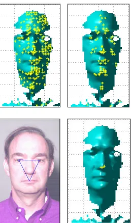
Only points within a certain mean and variance threshold are considered as nose tip candidates. Fig. 2 shows the nose tip candidates before and after the mean and variance thresholding.
Fig. 2: Nose tip candidates before and after mean and variance thresholding.
From Fig. 2, it can be observed that after thresholding, there is a concentration of nose tip candidates in the nose, chin, lips and cheeks area. This is because those areas are also protruding like the nose. Therefore, choosing the point with the densest amount of neighbouring nose tip candidates might not produce the correct nose tip. Consequently, it is proposed the next step is to determine the nose area.
III. NOSE AREA DETECTION
The nose area is always between the eyes and mouth area. Therefore, the next step in this proposed method is to locate the eyes and mouth. This is done by calculating the eye and mouth map using the method proposed by Hsu [8]. Eyes and mouth in the eye map and mouth map respectively are brighter regions compared to other parts of the face. After thresholding, the eyes and mouth area are found.
Fig. 3: Eyes and mouth areas detected for different head poses.
For two eye blobs, the nose area is within the triangle formed as shown in Fig. 3. For one eye blob, the nose area is within the polygon formed by the line drawn in Fig. 3, the skin boundary of the other half of the face and a horizontal line joining the line and boundary at the top and bottom of the line. A left face boundary is chosen if the single eye blob is a right eye and vice versa. Whether the single eye blob is a right or left eye is known by observing the position of the eye with regard to the mouth found.
IV. NOSE TIP DETECTION
Finally, the nose tip is detected by choosing the three pixels which have the densest amount of nose tip candidate neighbours and is within the nose area. Fig. 4 shows the step by step results of detecting the nose tip.
Fig. 4: Nose tip detection process.
V. RESULTS
[image:3.612.81.289.47.241.2]To test our proposed method, 100 random images from the UND database [9]-[11] were used. This database provides the depth information as well as a corresponding 2D image, which is suitable for our testing. Fig. 5, Fig. 6 and Fig. 7 shows examples of nose tip detection for different head poses on four different subjects.
Fig. 5 uses the proposed nose tip detection method. Fig. 6 uses a method that locates the nose tip by choosing the candidate which has the densest amount of nose tip candidate neighbours without using the nose area. Fig. 7 uses a method proposed in [5]. This method consists of taking each horizontal slice of the face and a circle centered on each point in the slice is drawn. In each circle, a triangle is drawn between the centre point and the two intersections between the slice and the circle. The point with the highest triangle height in each slice is noted. After processing all the slices, the points with highest triangle height will form the nose ridge. From these groups of points, the one with the highest height is taken as the nose tip.
[image:3.612.121.251.469.688.2]Fig 5: Nose tip obtained using proposed nose tip detection method.
Fig 7: Nose tip obtained using method proposed in [5]. From the results, it can be observed that out of the three methods tested, our proposed method is the only one that is able to locate the nose tip correctly for all the four different subjects.
The densest nose tip candidate neighbours method without using the nose area works for side faces but not for most frontal faces, as shown in Fig. 6. This is because frontal faces have dense nose tip candidates at the chin, forehead and cheek area, causing error in nose detection.
For the method proposed in [5], it works well with frontal faces but has problems with faces that is almost 90o facing the side. This is because with side faces, the nose is almost at the side and part of the nose may be missing. Therefore, the nose tip will not have much protrusion as compared to the cheek, as shown in Fig. 7. Besides that, this method fails if the subject’s head is tilted to the left, right, top or bottom. The reason is because at these positions, the nose tip at the horizontal slice will not have the largest protrusion compared to other parts of the face.
[image:4.612.311.543.52.154.2]After testing with the UND database, which consists of frontal faces and non-frontal faces, the results in Table 1, Table 2 and Table 3 were obtained. Table 1 shows the detection rate of locating the nose area while Table 2 and Table 3 shows the detection rate of the nose tip using different methods.
Table 1: Success rate for nose area detection Frontal Face Non-Frontal Face Success Rate for
Nose Area Detection
90% 83%
Table 2: Nose tip detection rate for frontal faces Proposed
Method
Densest Nose Tip Candidate
Method
Method Proposed
in [5] Success Rate
of Nose Tip Detection for Frontal Faces
[image:4.612.112.264.56.259.2]93% 35% 90%
Table 3: Nose tip detection rate for non-frontal faces Proposed
Method
Densest Nose Tip Candidate
Method
Method Proposed
in [5] Success Rate
of Nose Tip Detection for
Non-Frontal Faces
68% 15% 5%
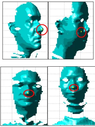
[image:4.612.324.527.313.510.2]Table 1 shows that the detection rate for the nose area, which is between the eyes and mouth area, is better for frontal faces compared to non-frontal faces. The faces with successful nose area detection are then used to perform nose tip detection. From the nose tip detection rate obtained in Table 2 and Table 3, it is observed that frontal face detection rate is also higher than non-frontal face. This is because for non-frontal faces almost facing 90o to the side, there is loss of data from the model obtained because the nose tip is at the edge. Sometimes, information from the edge is distorted and the nose may not appear properly. Fig 8 shows examples of nose tips successfully located in a face image.
Fig 8: Examples of nose tip detected.
VI. CONCLUSION
[image:4.612.70.300.571.737.2]well as non-frontal faces. The results obtained were good and we were able to detect the nose for faces at various angles. This shows that the method proposed is suitable to be implemented in an automatic 3D face recognition system. Further work will be done to improve the success rate of the nose tip detection.
REFERENCES
[1] W. Zhao, R. Chellappa, A. Rosenfeld, and P. J. Phillips, “Face Recognition: A Literature Survey,” UMD CfAR Technical Report CAR-TR-948, 2000.
[2] M.Gargesha, and S.Panchanathan, “A Hybrid Technique for Facial Feature Point Detection,” Proceedings. Fifth IEEE Southwest
Symposium on Image Analysis and Interpretation, pp. 134-138, 2002.
[3] M.S. Richman, T.W. Parks, and H.C. Lee, “A novel support vector machine-based face detection method,” In Proceedings of Record of
Thirty-Third Asilomar on Signals, Systems, and Computers, pp.
740-744, 1999.
[4] Gizatdinova, Y., and Surakka, V. 2006. Feature-based detection of facial landmarks from neutral and expressive facial images. IEEE Transactions on Pattern Analysis and Machine Intelligence, 28, 1, pp. 135-139, 2006.
[5] Ajmal S. Mian, M. Bennamoun and R. Owens, "Automatic 3D Face Detection, Normalization and Recognition", Third International Symposium on 3D Data Processing, Visualization and Transmission
(3DPVT), 2006.
[6] Xu, C., Wang, Y., Tan, T., Quan, L., 2004. Robust nose detection in 3D facial data using local characteristics.
Proc. ICIP'04, 1995-1998.
[7] I. Jolliffe, “Principal Component Analysis”, New York: Springer_Verlag, 1986.
[8] R.L.Hsu, “Face Detection and Modeling for Recognition,” Ph.D dissertation, Michigan State University, East Lansing, MI, United States of America, 2002.
[9] P. J. Flynn, K. W. Bowyer, and P. J. Phillips, “Assessment of time dependency in face recognition: An initial study,” Audio and
Video-Based Biometric Person Authentication, pp.44-51, 2003.
[10] K. Chang, K. W. Bowyer, and P. J. Flynn, “Face recognition using 2D and 3D facial data,” ACM Workshop on MultimodalUser
Authentication, pp.25-32, December 2003.