An Area Efficient Low Complexity
Architecture for Comparing Data Encoded
with Linear Block Codes
Chaithanya K1, Bhavya Das D 2
M.Tech Student (VLSI Design), Dept. of ECE, NCERC, Thrissur, Kerala, India1 Assistant Professor, Dept. of ECE, NCERC, Thrissur, Kerala, India 2
ABSTRACT: Nowadays data comparison plays an important role in computing systems to perform many operations. With the decrease of feature size and reduction of operating voltage of advanced chips, sensitivity to radiation increases drastically and this may affect multiple adjacent memory cells .An area efficient, low complexity, low latency architecture for matching data protected with linear block codes that can correct single errors, double-adjacent errors, triple-adjacent errorsand double-almost-adjacent errors is presented in this work. To detect and correct errors in a parallelized manner here error correcting codes are used. In addition, a new butterfly weight accumulator (BWA) is proposed for the efficient computation of the Hamming distance. Along with this new architecture modification is carried out at the gate level which significantly reduces the area .The performance of the proposed architecture is evaluated using Xilinx synthesis tool in terms of delay, area and power.
KEYWORDS: Data comparison, Error Correcting Codes (ECC), Hamming distance, Butterfly Weight Accumulator.
I.INTRODUCTION
In modern computing systems, data comparison logic has many applications and is inevitable. Data comparison is the process in which the incoming data is compared with the stored data in computing systems and according to the result further operations are carried out. So in order to provide better integrity and reliability the stored data is encoded before getting stored in the memory. The most important feature is that data comparison circuit always lies in the critical path of the computing systems and as a result, for the best outcomes this circuit must be implemented using low hardware complexity and in a robust manner. In recent computing systems the data is encoded using error correcting codes (ECCs) [5], [6] which provides better reliability [9].
During past days, data comparison was mainly carried out by using decode and compare methods. This is the way in which first we will fetch the data and then it is decoded and compared with the incoming data .This is a time consuming process since each data has to be decoded before comparison and if any defects were present in the memory that is never recovered .So we go for using the ECCs for encoding the data, in which the encoded data is in systematic form. Many error correcting codes, such as Hamming code [11] ,[8] matrix code, Golay code, convolutional code, etc., can be used to protect the data .But in many structures we go for using the Hamming codes because they can correct a single error and detect double errors but cannot correct double errors in the stored word [7].
Butterfly weight accumulator is an efficient structure which can be used to detect and correct single errors, double-adjacent errors, triple-double-adjacent errorsand double-almost-double-adjacent errors by computing Hamming distance effectively and for this a new coding was introduced and the area was reduced by modifying the structure at gate level. This paper mainly discusses about the conventional methods and direct comparison methods used for matching data stored in cache arrays.
In this brief, the rest of the paper is organized as follows. Section II reviews the related works in which we have the detailed study of conventional decode and compare architecture and direct compare architecture, which includes the architecture using saturate adders and butterfly weight accumulator. In Section III we go for the study of the proposed methodology and section IV evaluation of these architectures are analyzed and finally the conclusion in section V.
II.RELATED WORKS
This section covers the overall idea about the basic comparison circuits that are used in computing systems frequently. The conventional decode and compare circuit and the direct compare method called as encode and compare circuit are discussed here. The existing encode and compare circuit implemented using the saturate adders and the Butterfly Weight Accumulator (BWA) is discussed under this section.
A. Conventional Decode and Compare Architecture
In conventional decode and compare architecture used in cache array lookup table first the encoded data which is encoded by a (n, k)code is retrieved .Now this encoded data is passed through a decoder circuit and the data get decoded as kbits data from the n bits code word. Now the obtained data is compared with the original incoming data which has k bits. This is shown in Fig. 1.The main disadvantage of conventional architecture is that it make use of separate decoders for decode all the encoded data stored in the cache tag array. This results in area consumption and thus the delay for the critical path increases.
B. Direct Compare Architecture
In decode and compare circuit the main disadvantage is that whole data has to be decoded before comparison .This process may results in huge area and time consumption in the computing system’s critical path which is a serious issue. As a result of this the direct compare method which can be also called as encode and compare method was designed .In this structure we go for a simple modification in the circuit which results in less area and time utilization.
Incoming address
Fig.1.Conventional Decode and Compare Architecture
In direct encode and compare circuit instead of going for decoding all the stored information we uses an encoder for the incoming address ,which is encoded by the encoder and this encoded data is compared with the stored codewords and then get compared and thus saves the large area consumed by the decoders in the conventional method. Figure 2 shows the general architecture for the direct compare circuit. The main concept used in this architecture is to find the Hamming
Tag array
Decode
r
Correction logic
Comparator
distance using the Hamming distance circuit and according tothe Hamming distance the comparison of data is done and the conclusion is obtained.
Fig.2. General Direct Compare Architecture
Hamming distance circuit mainly has 3 parts [2]. To find the bitwise difference between the two code words, XOR gates are used as the bit-wise comparators. The outputs of the XOR gates from the first part is summed up using a summing circuit. The last part of the circuit compares the sum to the two distance thresholds and generates the final conclusion. The summing up circuit can be implemented by using the saturate adder circuit or by using the butterfly weight accumulator circuits.
III.PROPOSEDMETHODOLOGY
This section an area efficient, low complexity, low latency architecture for matching data protected with linear block codes that can correct single errors, double-adjacent errors, triple-adjacent errorsand double-almost-adjacent errors with reduced latency and complexity for data comparison by using the characteristics of systematic codes. In addition, a new processing element is presented to reduce the latency and complexity and area further.
A. Block diagram
The Fig.3 describes the flow of the proposed architecture. The incoming data is encoded by appending the parity bits. Then the encoded data is compared with the data in the memory which can be retrieved. The XOR bank and Butterfly formed weighted accumulator is used to find the number of bit changes and to calculate the number of ones which are fed into error correction and error deduction unit. Thus the output is obtained from the decision unit.
Fig.3. General BWA Based Architecture
Tag array
Comparator
Encoder
Match /MCA/New
Incoming
Address
Retrieved
codeword
Incoming
Address
Encoder
XOR Bank
BWA Structure
B. ECC codewords
Error detection and correction (EDAC) techniques are used to ensure that data is correct and has not been corrupted, either by hardware failures or by noise occurring during transmission or a data read operation from memory. There are many different error correction codes in existence. The reason for the different codes being used in different applications has to do with the historical development of the data storage, the types of data errors occurring, and the overhead associated with each of the error detection techniques.
For reliable communication, errors must be detected and corrected. Any error-correcting code can be used for error detection and correction. Error correcting code (ECC) or forward error correction (FEC) code is a system of adding redundant data, or parity data, to a message, such that it can be recovered by a receiver even when a number of errors were introduced, either during the process of transmission, or on storage.
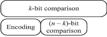
The ECC codeword is of a systematic form[10] in which the data and parity parts are completely separated as shown in Fig. 4.As the data part of a systematic codeword is exactly the same as the incoming tag field, it is immediately available for comparison while the parity part becomes available only after the encoding is completed.
Fig.4. Systematic representation of ECC codeword
Grounded on this fact, the comparison of the k- bit tags can be started before the remaining (n-k) bit comparison of the parity bits. Thus in the proposed architecture , therefore , the encoding process to generate the parity bits from the incoming tag is performed in parallel with the tag comparison , reducing the overall latency as shown in Fig.5.
Fig.5. Timing diagram in proposed architecture
C. Butterfly Formed Weight Accumulator
The most efficient architecture for matching data encoded with ECCs was introduced by making use of a new architecture [1] .Here in this architecture for summing up the difference between the two codewords instead of SAs, a new architecture was proposed and called as Butterfly Weight Accumulator (BWA) circuit.
Fig.6. First and second level circuits for a (8, 4) code.
The most important advantage of BWA circuit is that it does not require any additional circuitry and this can be also used to find out more number of errors and this errors can be corrected if any other coding was used instead of Hamming codes[1]. According to the number of errors detected and corrected the only change occurs in the decision unit, which can be easily put up without any additional circuitry. Thus the BWA based architecture provides low complexity, low latency architecture for matching data encoded with systematic error correcting codes.
TABLEI
TRUTH TABLE OF THE DECISION UNIT FOR A (8,4) CODE
Q or R or S
T U V Decision
0 0 0 x Match
0 0 1 x Fault
0 1 0 0 Fault
0 1 0 1 Mismatch
0 1 1 x Mismatch
1 x x x Mismatch
For the (8, 4) code Fig.6. Shows the first and second level circuits and the corresponding truth table is shown in Table I. Since U and V cannot be set simultaneously such cases are implicitly included in do not care terms in Table I.
D. Proposed Error Correcting Code
Due to the increasingly small memory densities, an SEU maycorrupt a single memory cell, two adjacent memory cells orthree adjacentmemory cells, resulting in a single error, a doubleadjacenterror or a triple-adjacent error. An SEU may also simultaneouslyaffect more than three memory cells, but this isnot very likely in a number of situations. An SEU may also resultin a double-almost-adjacent error. Supposing three adjacentmemory cells hold logic 1, 0 and 1 respectively, an SEU affectsthese three contiguous cells by discharging them all to logic 0.But since the second (middle) cell was previously set to logic 0, this SEU will only corrupt the first and third cells, resulting in adouble almost adjacent error. The proposed code can correct asingle error, a double-adjacent error, a triple-adjacent error or adouble-almost-adjacent error caused by an SEU [3].
under fault-free conditions. The below given equations can be transformed into matrix form and can be used to detect and correct errors as explained in [8].
(1)
E. Design for proposed BWA
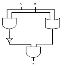
The proposed architecture is developed with the help of modified half adder and modified XOR gate and thus this reduces the area consumed by the proposed architecture [4]. The modified XOR gate has 1 gate less than the conventional XOR gates (AND-OR-NOT implementation as shown in Fig.7.
Fig. 7. Modified half adder
Modified half adder has 2 gates less than the conventional half adder as shown in Fig.8.
IV.EXPERIMENTALRESULTS
In this paper all the techniques discussed above are implemented using the Verilog. Modelsim was used for the simulation of the Verilog code for the data comparison method used in cache array lookup table and the synthesis of the same was done by using Xilinx ISE 6.1i software.By analyzing the results obtained by simulating the codes using the above software we can understand that the BWA based architecture is far better than other designs in terms of area and latency .The results for simulation of (24,18) ECC codeword are shown in Table II.
In the proposed architecture the BWA architecture is modified using modified XOR and half adder circuits. All these structures was simulated and synthesized using Modelsim and Xilinx .From the Table II we can clearly understand that the area consumed by BWA architecture is much smaller than other implementations discussed so far. The delay of the architecture is measured by summing up the time taken for performing the overall functions such as encoding, decoding, correcting and comparing.
TABLEIII EXPERIMENTALRESULTS
Architecture Simulation Results
Area(slices) Delay(ns)
Decode and
Compare 971 74.961
Encode and
compare-SA based 644 47.256
Encode and compare-BWA
based
619 8.128
Encode and compare-BWA
modified
558 8.128
Encode and compare- BWA –
Hamming modified
482 8.128
The Table II shows that the BWA based architecture is highly operative in terms of both complexity and latency. The BWA based architecture reduces the latency even if the length of codeword increases .As we compare this structure with SA based structure we can understand that in SA based structure as the codeword length increases the complexity of the architecture increases due to the addition of extra SA circuitry to sum up the Hamming distance but this get eliminated in BWA based structures. There as the codeword length increases only the HAs are added additionally where the critical path of HA consists of only one gate. From the below Table II we can understand that the by combining the new SEU tolerant memory error correcting codes with the new architecture along with maintaining the low complexity and low latency the architecture was used to detect more number of errors.
V.CONCLUSION
In this paper, a new architecture has been presented for matching the data protected with an ECC. The proposed architecture examines whether the incoming data matches the stored data if a certain number of erroneous bits are corrected. To reduce the latency, the comparison of the data is parallelized with the encoding process that generates the parity information.An area efficient, low complexity, low latency architecture for matching data protected with linear block codes that can correct single errors, double-adjacent errors, triple-adjacent errorsand double-almost-adjacent errors is presented in this work.
efficient out of all other techniques in terms of latency and complexity. To have the maximum utilisation of the used structure, i.e., the butterfly weighted accumulated a new coding was in cooperated. The usage of modified half adder and XOR gate further helps in reducing the area of the used architecture.
REFERENCES
[1] Byeong Yong Kong, Jihyuck Jo, HyewonJeong, Mina Hwang, Soyoung Cha, Bongjin Kim, and In-Cheol,“Low-Complexity Low-Latency Architecture for Matching of Data Encoded With Hard Systematic Error-Correcting Codes”, IEEE Transactions On Very Large Scale Integration (VLSI) Systems., vol.22, no.7,pp.1648-1652, July 2014.
[2] W. Wu, D. Somasekhar, and S.L. Lu, “Direct compare of information coded with error-correcting codes,”IEEE Trans. Very Large Scale Integration (VLSI) Systems., vol. 20, no. 11, pp. 2147–2151, Nov. 2012.
[3] Xiaoxuan She, N. Li, and D. Waileen Jensen, “SEU Tolerant Memory Using Error Correction Code “, IEEE Trans. On Nuclear Science, vol. 59, no. 1, pp.205-210 Feb. 2012.
[4] KandurAshwini, Dr. G. Kanaka Durga, P. Koti Lakshmi, “Reduced Area Low Power Square Root Carry Select Adder,” International Journal of Science and Applied Information Technology (IJSAIT), vol. 3 , no.4, pp.33 - 38, Sep. 2014.
[5] J. Chang, M. Huang, J. Shoemaker, J. Benoit, S.–L. Chen, W. Chen,S. Chiu, R. Ganesan, G. Leong, V. Lukka, S. Rusu, and D. Srivastava,“The 65-nm 16-MB shared on-die L3 cache for the dual-core Intel xeon processor 7100 series,” IEEE J. Solid-State Circuits, vol. 42, no. 4, pp.846–852, Apr. 2007.
[6] H. Ando, Y. Yoshida, A. Inoue, I. Sugiyama, T. Asakawa, K. Morita,T. Muta, T. Motokurumada, S. Okada, H. Yamashita, Y. Satsukawa, A. Konmoto, R. Yamashita, and H. Sugiyama, “A 1.3 GHz fifth generation SPARC64 microprocessor,” in ISSCC. Dig. Tech. Papers, 2003, pp. 246–247.
[7] Pedro Reviriego, Salvatore Pontarelli, Juan Antonio Maestro, and Marco Ottavi, “A Method to Construct Low Delay Single Error Correction Codes for Protecting Data Bits Only,” IEEE Trans. Computer-Aided Design of Integrated Circuits and Systems., vol. 32, no. 3, pp. 479 - 483, March 2013.
[8] V. Gherman, S. Evain, N. Seymour, and Y. Bonhomme, “Generalized parity-check matrices for SEC-DED codes with fixed parity,” in Proc. IEEE On-Line Testing Symp., Jul. 2011, pp. 198–20.
[9] J. D. Warnock, Y.-H. Chan, S. M. Carey, H. Wen,P. J. Meaney, G. Gerwig and W. V. Huott “Circuit and physical design implementation of the microprocessor chip for the Enterprise system,” IEEE J. Solid-State Circuits, vol. 47, no. 1, pp. 151–163,Jan. 2012.
[10] S. Lin and D. J. Costello, Error Control Coding: Fundamentals and Applications, 2nd ed. Englewood Cliffs, NJ, USA: Prentice-Hall, 2004 [11] H. J. Tausch, “Simplified birthday statistics and hamming EDAC,” IEEE Trans. Nucl. Sci., vol. 56, no. 2, pp. 474–478, Apr. 2009.