i
tif c n
e C
i o
c n
S f
l e
a r
n e
o n
i c
t e
a 2
nr 0
et 1
1 n I
ISC 2011
Proceeding of the International Conference on Advanced Science,
Engineering and Information Technology 2011
Hotel Equatorial Bangi-Putrajaya, Malaysia, 14 - 15 January 2011
ISBN 978-983-42366-4-9
ISC 2011
International Conference on Advanced Science, Engineering and Information Technology ICASEIT 2011
Cutting Edge Sciences for Future Sustainability Hotel Equatorial Bangi-Putrajaya, Malaysia, 14 - 15 January 2011
SR
IE
AUNVIIT
NI
ES E
D K
O B
IN N
R AG
JA A
L S
A A
E N
P M
N A
A L
U A
T Y
A S
S A I
REP
N I
NOI TAI COSSA STNEDUTS NA ISENOD
Organized by Indonesian Students Association Universiti Kebangsaan Malaysia Proceeding of the
H
∞
Robust Controller Design for an Induction
Generator Driven by a Variable-Speed Wind Turbine
Seyed Mohammad Hoseini#, Seyed Vali Heidari*
# Department of Electrical Engineering, Islamic Azad University, Mehriz Branch
Mehriz, 8981883114, Iran
Tel.:+983525229100, E-mail: [email protected]
* Department of Electrical Engineering, Islamic Azad University, Mehriz Branch Mehriz, 8981883114, Iran
robust controller for the static synchronous compensator (STATCOM) and the variable blade pitch in a wind energy conversion system (WECS) is designed to be controlled voltage and mechanical power. This controller leading to satisfactory damping characteristics achieved for the closed loop system. Effects of various system disturbances on the dynamic performance have bee n simulated, and the results comparison with output feedback controller reveal that the proposed controller is effective in regulating the
with the above linear simulation shows that the simulations carried out for small changes in system inputs is sufficiently accurate.
and the results show robust controller design as well as fluctuations resulting from the short circuit is damped.
Keywords— Induction generator (IG), static synchronous compensator (STATCOM), wind energy conversion system (WECS), robust controller.
I. INTRODUCTION
Wind energy conversion systems (WECS), energy in the blowing wind into electrical energy to convert. A very variable wind resource that can’t be stored and WECS must be based on the act. Technology using wind to generate electricity, providing a new source of electricity with the fastest growth in the world. Wind energy by a wind turbine blade that has one or more mechanical energy is converted. Turbine generator by a gearbox to Copley.
Some of the turbines, including a controlling blade pitch angle control amount power can be transferred. Generator can be a synchronous or Asynchronous. Induction generators are being increasingly utilized in a WECS since they are relatively inexpensive, rigid, and require low maintenance. However, the impact of ever-changing wind speed on power quality, coupled with the need of excitation current for induction generator (IG), make the mechanical power control and voltage regulation indispensable to the wind-driven induction generator system. By far, the most effective
way of controlling the mechanical power captured by the wind turbine is to adjust the rotor blade pitch angle. Blade pitch is analogous to the throttle value in conventional steam turbines, except that the speed of control in a steam turbine [1], [2]. It can be employed to regulate mechanical power input and real power output of the WECS.
However, the reactive power required by the IG can be provided by a shunt capacitor bank, but it may cause excessive over-voltage during disconnection. Moreover, the amount of capacitance required for excitation varies with the generator speed [3]. Thus, if a fixed shunt capacitor is connected across the terminals of the IG, the terminal voltage will vary with generator speed. To achieve continuous voltage regulation under varying system conditions, static synchronous compensators (STATCOMs), have been employed in the literatures [4, 5, 6, 7, 8]. The basic principle of a STATCOM installed in a power system is to generate a controllable ac voltage behind a coupling transformer and a filter by a voltage-sourced inverter (VSI) connected to a dc capacitor. The output voltage of the VSI Tel.:+983525229101, E-mail: [email protected]
load voltage and stabilizing the generator rotating speed for WECS. The nonlinear simulation was conducted and that comparison
for review performance against large disturbances from a symmetrical three-phase short circuit at infinity bus bar has been used
can be controlled to be greater than the line voltage in order to provide reactive power to the wind-driven IG.
Most methods of analysis and design of control systems based on mathematical model that the index of approximation and simplification of the linear and generally non-linear equations around the operating point to come. . Thus if a change occurs in the model parameters, the results will not necessarily true. Should be noted that physical systems cannot be with a more precise mathematical model to describe. So the real problem in the system model uncertainty is inevitable. Due to this uncertainty and the inevitable turbulence in practice, motivation is the emergence of robust control methods. In this paper, the H∞ robust controller for voltage regulation system and the mechanical power is used.
The effectiveness of the proposed control strategy is evaluated under operating conditions on damping low frequency oscillations in comparison with the output feedback controller to demonstrate its robust performance. Also the results reveal that system performance with H∞ robust controller in spite of disturbance and various uncertainties is very satisfactory.
II. SYSTEM MODELS
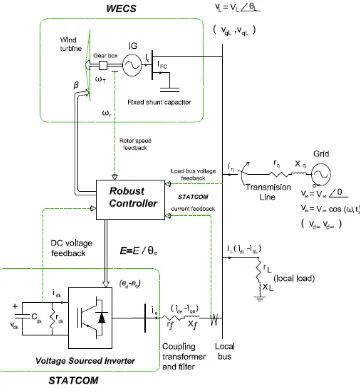
Fig. 1 depicts the one-line diagram of an induction generator driven by a variable-speed wind turbine and connected to a grid through a transmission line. A robust controller is utilized to control the wind turbine mechanical power through the variable blade pitch and the STATCOM, respectively. The reactive power required by the IG in steady-state operating condition is supplied by a fixed shunt capacitor bank, as shown in Fig. 1. To maintain constant
load bus voltage (Vl ) under disturbance conditions, a
STATCOM, which is capable of adjusting its output voltage and reactive power output based on system requirements, is employed. The STATCOM is connected to the load bus through a coupling transformer and a filter.
Fig. 1 System configuration
Induction Generator Model
The per unit flux-linkages for the stator and rotor
circuits of the induction generator described in d-
and q-axes are as follows [9], [10]:
(1) qs
s w ds i s r dl v b w
ds ϕ
ϕ = ( + )+
.
(2) ds
s w qs i s r ql v b w
qs ϕ
ϕ = ( + )−
.
(3) qr
r w s w dr i r r dr v b w
dr ϕ
ϕ ( ) ( )
.
− + −
=
(4) dr
r w s w qr i r r qr v b w
qr ϕ
ϕ ( ) ( )
.
− − −
=
Where a synchronous reference frame rotating at the electrical angular speed corresponding to the fundamental
frequency of the grid voltage, herein denoted as
w
s, isadopted. Furthermore
w
b,w
r,V
dL,V
qL are base and rotorangular speeds and stator voltage in d-axis and q-axis, respectively.
The electromechanical torque in per unit can be written in terms of stator flux linkages and currents as
(5) ds
i qs qs i ds e
T =ϕ −ϕ
The per unit rotor acceleration is given by
(6)
) (
.
2
1 u
r w T D e T m T T H u r
w = − −
Where
T
mis the per unit mechanical torque of the windturbine, and
H
T andD
Tare the equivalent inertia constantand the equivalent damping constant of the wind turbine-induction generator system, respectively.
Model
The mechanical power output of a wind turbine
can be written as [2]
(7)
3 2
1
w V p AC m
P = ρ
where
ρ
is the air mass density,V
wis the wind speed,A
is the rotor swept area, andp
C
is a power coefficientrepresenting the fraction of power extracted from the aerodynamic power in the wind by a practical wind turbine.
The power coefficient
C
pvaries with the wind speed, therotational speed of the turbine, and the turbine blade parameters. The MOD-2 wind turbine model [11], [12] with the following closed-from approximate relationship for
p
C
is used:(8) γ
β γ
R
e R
p C
17 . 0
6 . 5 2 022 . 0 2
1 −
− −
=
The tip speed ratio
γ
is defined as (9) w V R T w = γWhere
w
Tis the rotating speed of the wind turbine .It is observed from (7)-(9) that the mechanical power
output of a wind turbine is related to the turbine speed
w
T,wind speed
V
w, and the pitch angleβ
. An increase in thepitch angle
β
, which results in a decrease in the power ofwind turbine when
P
mcontinues to increase with increasingwind speed.
In this work, the initial pitch angle (
β
o) is chosen to beo
46
.
13
such that the wind turbine delivers a mechanicalpower of 0.81 per unit (p.u.) for a 30 miles/h (mph) wind at hub height.
STATCOM Model
For a balanced three-phase system, the
STATCOM model can be described in per unit
using the variables in d- and q-axes synchronous
reference frame as [14]
(10)
(
ed)
dl v f X b w qe i s w de i f X f r b w de
i. =− + + −
(11)
− + − − = q e ql v f X b w de i s w qe i f X f r b w qe i.In Fig. 1, the instantaneous powers at the ac and dc sides of the voltage-sourced inverter are equal, giving the following power balance equation:
(12) qe q de d dc
dc
i
e
i
e
i
v
=
+
The per unit dc-side circuit equation is
(13)
−
=
dc dc dc dc dcr
v
i
C
v
.1
Where
r
dcis used to represent the inverter switching loss.More details can be found in [5].
III. DERIVATION OF THE STATE EQUATIONS
In order to determine proper control signal for the STATCOM through a systematic design approach, the dynamic system equations as given in section 2 are linearized around a nominal operating point in the form as
(14a)
x
C
y
u
B
x
A
x
∆
=
∆
∆
+
∆
=
∆
.
.
.
.where (14b) T qe de qtl dtl qs ds dr qr dc u r ql dl ql dl
i
i
i
i
v
w
i
i
v
v
x
]
,
,
,
,
,
,
,
,
,
,
,
,
[
∆
∆
∆
∆
∆
∆
∆
∆
∆
∆
∆
∆
∆
∆
=
∆
ϕ
ϕ
ϕ
ϕ
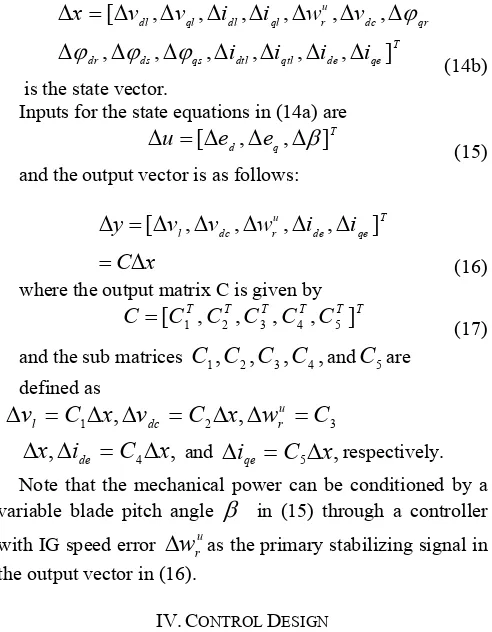
is the state vector.
Inputs for the state equations in (14a) are
(15)
T q
d
e
e
u
=
[
∆
,
∆
,
∆
β
]
∆
and the output vector is as follows: (16)
x
C
i
i
w
v
v
y
T qe de u r dc l∆
=
∆
∆
∆
∆
∆
=
∆
[
,
,
,
,
]
where the output matrix C is given by
(17) T T T T T
T
C
C
C
C
C
C
=
[
1,
2,
3,
4,
5]
and the sub matrices
C
1,
C
2,
C
3,
C
4,
andC
5aredefined as
3 2
1
x
,
v
C
x
,
w
C
C
v
ur dc
l
=
∆
∆
=
∆
∆
=
∆
,
,
i
C
4x
x
∆
de=
∆
∆
and∆
i
qe=
C
5∆
x
,
respectively.Note that the mechanical power can be conditioned by a
variable blade pitch angle
β
in (15) through a controllerwith IG speed error
∆
w
ruas the primary stabilizing signal inthe output vector in (16).
IV. CONTROL DESIGN
The main objective of the proposed controller is to regulate certain output measurements and drive system states to equilibrium operating points when the wind-driven induction generator system is subjected to various disturbances.
A. Output Feedback Control
In the design of the output feedback controller, the pole placement approach based on linear quadratic control (LQC) will be used. For the linear system described in (14a), the
linear quadratic state feedback control
∆
u
that minimizesthe performance index
(18)
(
)
∫
∞∆
∆
+
∆
∆
=
02
1
dt
u
R
u
x
Q
x
J
T TWhere Q is the weighting matrix of the state variable variations and R that of the control effort, is given by [13]
The output feedback control
∆
u
is given by(19)
y
K
u
=
−
o∆
∆
For more explanation can be referred to [5].
B. Robust Control
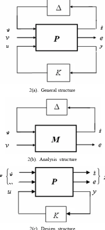
General structure of robust control problems is shown in
Fig. 2(a). that
∆
indicates system uncertainty, P isrespectively. In controller analysis problems, K considers as a part of main system and we can compose it with certain part of P and made unique system M, as shown in Fig. 2(b). in this figure M is results of generalized system P and K controller as follows:
(20)
21 1 22
12
(
)
)
,
(
P
K
P
P
K
I
P
K
P
F
M
=
l=
n+
−
−Where P is:
(21)
=
u
w
P
P
P
P
y
z
22 21 12 11also, generalized system model can be described by state space, as follows:
(22)
u
D
w
D
x
C
y
u
D
w
D
x
C
z
u
B
w
B
Ax
x
22 21 2 12 11 1 2 1 .+
+
=
+
+
=
+
+
=
In design problems, the aim is the K stable controller design so z outputs shown in Fig. 2(c) can be minimum.
2(a). General structure
2(b). Analysis structure
2(c). Design structure
Fig. 3. General structure of robust control problems
C. Robust Control based on H∞
Structure design shown in Figure 2(c), consider. Transfer matrix between the Z regulation outputs and W unexpected inputs is express with conversion linear - fractional as the following: 21 1 22 12 11 L
zw F(P,K) P P K(I P K) P
T = = + − −
(23) the H∞ standard control problem explain by finding K(s) sustainable internal control system for generalized P system
such that extreme form closed loop transfer function Tzw is
minimum. In other words, for δmin must have:
Stablizing ) s ( K zw T
Find ∞〈γ
(24) Controller with the following equation can be expressed: [15,17]
x K
u=− cˆ (25)
where
xˆ
is given by;xˆ X B D xˆ C yˆ , xˆ X B wˆ ) yˆ y ( K z wˆ B u B xˆ A xˆ T 1 21 2 2 T 1 2 e 1 2 ∞ − ∞ − ∞ + = = − + + + =
γ
γ
& (26)additional term of wˆ Estimates of the worst disturbance
input to the system. z∞Ke is gain of visible and KC is the gain of controller that determine as the following relationship : 1 2 1 T 21 21 21 21 T 12 1 T 2 e 1 12 T 12 12 1 T 12 T 2 12 C ) Y X I ( z ) D D ( D~ , D~ ) D B C Y ( K ) D D ( D~ ), C D X B ( D~ K − ∞ ∞ ∞ − ∞ − ∞ − = = + = = + =
γ (27)
Where x and y are the answers of Riccati equation of controller and visible. Means :
− − − − − = − − − − − = − ∞ − ∞ T 2 21 T 21 1 T 1 1 2 21 T 2 1 T 1 2 2 21 T 21 1 T T 12 12 2 1 1 T 2 T 12 2 T 1 1 2 T 12 12 2 ) C D~ D B A ( B B~ C D~ C C C C D~ D B A Ric Y ) C D D~ B A ( C~ C~ B D B B B C D D~ B A Ric X T
γ
γ
(28) Where ; C ) D D~ D I (C~ 1
T 12 21 12
1 = − D D )
~ D I ( B
B~ 21 21
T 21 1
1 = −
Can be shown that there is a sustainable controller if the answer of riccati equation be positive semidefinite and there is the follow relationship :
2 ) Y X
( γ
ρ ∞ ∞ ≤ (29)
V. SIMULATION RESULTS
In this paper, controller designed and under survey system simulated with using MATLAB software. In this section, the
results of system simulation with H∞ robust controller is
being introduced.
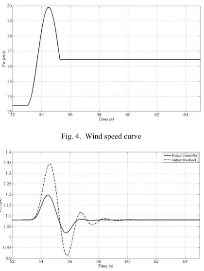
The dynamic performances of robust and output feedback controllers for the WECS were compared under disturbance and the results are depicted in Figs. 5, 6, 7.
caused by increasing wind speed if the pitch angle was fixed. However, as demonstrated in Fig. 3, the wind-sensorless robust controller generated a pitch angle command as soon as the wind speed began to increase.
A three-phase short circuit at the infinite bus at t=30 s was chosen to compare the performance of two controllers. the response of closed loop system under this disturbance is shown in figs. 8-10. The bus bar voltage and dc-capacitor voltage were returned to its reference value in very short time and swings amplitude with proposed controller is less than output feedback controller.
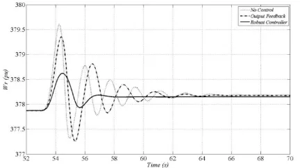
Also non-linear simulation results comparison for without control, output feedback and robust control is shown in figs. 11-13. As we can see, designed controller damps available disturbances in nominal system in spite of uncertainty in system parameters as well.
Fig. 4. Wind speed curve
Fig. 5. Changes of bus bar voltage with either output feedback and robust controller
Fig. 6. Changes of dc-capacitor voltage with either output feedback and robust controller
Fig. 7. Changes of rotor angular speed with either output feedback and robust controller
Fig8. Dynamic response of bus bar voltage for short circuit with either output feedback and robust controller
Fig. 9. Dynamic response of dc-capacitor voltage for short circuit with either output feedback and robust controller
Fig. 11. Dynamic response of bus bar voltage for non-linear simulation
Fig. 12. Dynamic response of dc-capacitor voltage for non-linear simulation
Fig. 13. Dynamic response of rotor angular speed for non-linear simulation
VI. CONCLUSION
In this paper, we discussed about H∞ robust controller
design for wind energy conversion system with STATCOM. A STATCOM and blade pitch control system has been successfully designed to regulate the load bus voltage and stabilize rotor speed for an induction generator in a
variable-speed WECS . Simulation results indicate that the H∞ robust
controller designed for the STATCOM and blade pitch is capable of improving
WECS dynamic responses in case of disturbances. It is also noted that generator speed feedback instead of wind speed feedback for the robust controller provides satisfactory transient response in stabilizing generator speed. Variant disturbance effects in dynamic performance of system simulated, and results reveal that the proposed controller in bus bar voltage regulation and improvement of system swing damping is very effective, also with surveying the results, it can be found that system performance with proposed
controller in spite of disturbance and various uncertainty is very satisfactory.
References
[1] A. Murdoch, R. S. Barton, J. R. Winkelman, and S. H. Javid, “Control design and performance analysis of a 6 MW wind turbine-generator,”IEEE Trans. Power App. Syst., vol. PAS-102, no. 5, pp. 1340–1347, Dec.1983.
[2] L. L. Freris, Wind Energy Conversion Systems. Englewood Cliffs, NJ: Prentice-Hall, 1990.
[3] S. S. Murthy, O. P. Malik, and A. K. Tandon, “Analysis of self-excited induction generators,” Proc. Inst. Elect. Eng.–C, vol. 129, no. 6, pp. 260–265, Nov. 1982.
[4] C. D. Schauder and H. Mehta, “Vector analysis and control of advanced static VAR compensators,” Proc. Inst. Elect. Eng.–C, vol. 140, no. 4, pp. 299–306, Jul. 1993.
[5] L. Chen, Y. Hsu., “Controller Design for an Induction Generator Driven by a Variable-Speed Wind Turbine”, IEEE Trans. on Energy Conversion, Vol. 21, no 3, pp. 625-635, Sep. 2006.
[6] C. T. Chang and Y. Y. Hsu, “Design of UPFC controllers and supplementary damping controller for power transmission control and stability enhancement of a longitudinal power system,” Proc. IEE–Gener. Transm. Distrib., vol. 149, no. 4, pp. 463–471, Jul. 2002. [7] W. L. Chen and Y. Y. Hsu, “Direct output voltage control of a static synchronous compensator using current sensorless d–q vector-based power balancing scheme,” in Proc. IEEE/PES T&D Summer Meet., 2003, vol. 2, pp. 545–549.
[8] Z. Saad-Saoud, M. L. Lisboa, J. B. Ekanayake, N. Jenkins, and G. Strbac, “Application of STATCOMs to wind farms,” Proc. IEE– Gener. Transm. Distrib., vol. 145, no. 5, pp. 511–516, Sep. 1998. [9] E. S.Abdin and W. Xu, “Control design and dynamic performance
analysis of awind turbine-induction generator unit,” IEEE Trans. EnergyConvers., vol. 15, no. 1, pp. 91–96, Mar. 2000.
[10] C. M. Ong, Dynamic Simulation of Electric Machinery Using MATLAB/ SIMULINK. Englewood Cliffs, NJ: Prentice-Hall, 1998. [11] P. M. Anderson and A. Bose, “Stability simulation of wind turbine
systems,” IEEE Trans. Power App. Syst., vol. PAS-102, no. 12, pp. 3791–3795, Dec. 1983.
[12] O. Wasynczuk, D. T. Man, and J. P. Sullivan, “Dynamic behavior of a class of wind turbine generators during random wind fluctuations,” IEEE Trans. Power App. Syst., vol. 100, no. 6, pp. 2837–2845, Jun. 1981.
[13] S. Skogested and I. Postlethwaite, “Multivariable Feedback Control”, John Wiley & Sons, 1996.
[14] P. H. Huang and Y. Y. Hsu, “An Output Feedback Controller for a Synchronous Generator”, IEEE Trans. Aerosp. Electron. Syst., vol. 26, no. 2, pp. 337–344, Mar. 1990.
[15] A. Jain, et al., “Voltage Regulation with STATCOMs: Modeling, Control and Results”, IEEE Trans. on PWRD, vol. 21, no. 2, pp. 726-735, April. 2006.
[16] M. Parniani and M.R. Iravani, “Optimal Robust Control Design of Static VAR Compensators”, IEE Proc., Gene. Trans. Distrib, 145, (3), pp. 301-307. 1998.