Ijeas
Ideal Journal of Engineering and Applied Sciences
2(3) 119-123
Ijeas
© Ideal True Scholar (2016) (ISSN: 2067-7720)
http://ijeas.truescholar.org
119
BIDIRECTIONAL DC-DC CONVERTER WITH OUTER LOOP VOLTAGE BASED
ON FUZZY PID CONTROL
Guangya Liu, Jiabing Chen And Xiang Li
School of Electrical and Electronic Engineering, Hubei University of Technology
Wuhan, 430068, Hubei Province, China
Corresponding Author: Guangya Liu
__________________________________________________________________________________________
ABSTRACT
This paper introduces the Bidirectional DC-DC Converter with Outer Loop Voltage Based on Fuzzy PID Control. Since the traditional PID controller cannot better balance the dynamic and static performance problems, we took Boost converter as an example and proposed a double closed-loop control system with the outer voltage loop based on fuzzy PID control and the inner voltage loop using PI control in view of the fact that in fuzzy control, it is unnecessary to establish the accurate mathematical model of the controlled object. And then we designed a bidirectional DC-DC converter with the outer loop voltage using fuzzy PID control. A Boost simulation model was established in Matlab/Simulink. The contrastive simulation experiments show that compared with the traditional PID control methods, the response speed and the output voltage ripple of the bidirectional DC-DC converter are greatly reduced. It means that the proposed fuzzy PID control on the outer loop voltage can solve the nonlinear problems of the bidirectional DC-DC converter, and represents an emerging trend in physical sciences and applied sciences as well.
© Ideal True Scholar
KEYWORDS:Bidirectional DC-DC Converter; Fuzzy PID Control; Nonlinearity; Control Performance
__________________________________________________________________________________
INTRODUCTIONIn recent years, with the rapid development of new energy technology, bidirectional DC-DC converter has been widely used in the new energy vehicles. bidirectional DC-DC converter is a kind of strongly nonlinear system. How to make the converter system work steadily and fast is a hot research area[1-3]. With the development of modern control theory, nonlinear control has been widely used in the control of power electronic converters, such as the sliding mode control, feedback linearization, passive control, neural network control and fuzzy control. Literature [4] analyzes the nonlinear characteristics of traditional converter and bidirectional DC-DC converter, puts forward the feedback linearization and high-order sliding mode control to solve the
nonlinear problems of bidirectional DC-DC
converters and traditional converters. Literature [5] is a nonlinear problem for the bidirectional DC-DC converter, combined with the advantages of sliding mode control and sliding mode variable structure controller, using both switch control method, obtained the good robustness and rapidity.
Although the above methods can better solve the problem of nonlinear system, the structure of controller is too complex, difficult to practice. Based on the advantages of fuzzy control in solving nonlinear problems, the system uses fuzzy PID control voltage outer loop and PI control current inner loop, which constitutes voltage and current
double closed loop control. Voltage loop control keeps the output voltage in a timely manner to track the given value, current loop control can effectively reduce the peak and ripple of the output current ,improve the response speed.
TOPOLOGICAL STRUCTUREAND WORKING PRINCIPLE
The topology of the bidirectional DC-DC converter has a lot of kinds, compared with other bidirectional DC-DC converter, bidirectional half-bridge DC-DC converter has small voltage and current stress, and use less number of inductance, so as to reduce the cost and volume. After using the method of multiple technology, it can effectively reduce the input and output current ripple, thereby reduce the design difficulty of inductance. The most important is that the multiple design can achieve a wide voltage output, this is a big advantage for the charging and discharging performance of hybrid electric vehicle
[6-7],so this article using the two phase interleaved
bidirectional DC-DC converter to meet the
120 Fig. 1 Topology of the two phase interleaved
bidirectional DC-DC converter
When the hybrid electric vehicle starts or accelerates, the two phase interleaved bidirectional DC-DC converter works in Boost mode, the energy flows from V1 to V2,switch tube S1, S3stagger work, switch
tube S2, S4does not work, and its reverse parallel
diode D2, D4 are the fly-wheel diode.
When the hybrid electric vehicle stops or slows down, the two phase interleaved bidirectional DC-DC converter works in Buck mode, the energy flows from V2 to V1,switch tube S2, S4stagger work, switch
tube S1, S3 does not work,and its reverse parallel
diode D1, D3are the fly-wheel diode.
SYSTEM STRUCTUREAND CONTROLLER DESIGN
Control System Structure
The two phase interleaved bidirectional DC-DC converter uses voltage and current double closed loop control structure. According to the deviation between the voltage setting and the output voltage, the voltage controller adjusts the current setting in real time, the current controller controls PWM signal and the output is always followed by a given, stable output voltage and current[8-9].In the process of booster, the dc voltage ripple can be reduced effectively, ensure
that drive performance; in the process of
decompression, the voltage output of the converter is steady, and the effect of the current ripple on the battery charging performance is reduced.
The traditional double closed loop control uses the PI controller to adjust the switch device. However, due to the nonlinear characteristics of the bidirectional DC-DC converter, control often can not reach the expected effect. he voltage outer loop uses fuzzy PID control to modify the parameters of the controller, which can improve the adaptive ability of the nonlinear system. The block diagram of the control structure is shown in figure 2.
fuzzy PID
GPWM
PI
PI Gid(s)
Hi(s)
Hi(s)
Gid(s)
GPWM
Hv(s)
Gvi(s)
+ + + + -ref V 1/2 1 V
Fig. 2 Control block diagram of the system
Design of Fuzzy PID Controller
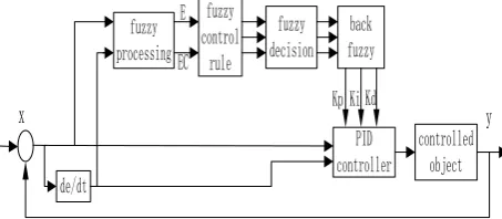
Fuzzy PID control is a kind of intelligent control method, using the basic theory and method of fuzzy mathematics, the rules of the condition and operation represented by fuzzy sets, and the fuzzy control rules of the relevant information is stored into the computer knowledge base, then according to the actual situation of the control system, the computer uses fuzzy inference to set of PID control parameters online, so as to achieve the best adjustment of PID parameters[10].The input of the fuzzy controller is error e and error change ec, to achieve the purpose of real-time correction KP, KI, KD, make the PID
parameter can be adjusted continuously with the change of system structure and the actual situation. Figure 3 is a block diagram of fuzzy PID.
fuzzy processing fuzzy control rule fuzzy decision back fuzzy PID controller controlled object de/dt
x
y
E ECKp Ki Kd
Fig. 3. Block diagram of fuzzy PID
1) Selection of Input and Output Variables
Output voltage deviation and deviation change rate of the bidirectional DC-DC converter is used as the input variable of the fuzzy controller, the parameters of the PID controller KP, KI, KD are modified by the fuzzy controller in real time. The correction formula is as follows:
D D D I I I P P P K K K K K K K K K ' ' ' (1)
2) Determination of Fuzzy Rules
Ideal Journal of Engineering and Applied Sciences (ISSN: 2067-7720) 2(3):119-123 Bidirectional Dc-Dc Converter With Outer Loop Voltage Based On Fuzzy PID Control
121 follows:{NB, NM, NS, ZO, PS, PM, PB}, respectively defined the domain ΔKP={0.3, 0.2,
-0.1, 0, -0.1, 0.2, 0.3}, ΔKI={-0.06, -0.04, -0.02, 0,
0.02, 0.04, 0.06}, ΔKD={-3, -2, -1, 0, 1, 2, 3}. In
order to facilitate the design, take the input e, ec and the output KP, KI, KD membership functions are
based on triangle function[11]. Fuzzy rule is “if… then…” conditional statement[12]. The specific fuzzy
control rules table is shown in table 1, table 2, table 3.
Tab. 1 fuzzy rule table of ΔKP
ec
ΔKP
e
NB NM NS ZO PS PM PB
NB PB PB PM PM PS PS ZO NM PB PB PM PM PS ZO ZO NS PM PM PM PS ZO NS NM ZO PM PS PS ZO NS NM NM PS PS PS ZO NS NS NM NM PM ZO ZO NS NM NM NM NB PB ZO NS NS NM NM NB NB
Tab. 2 fuzzy rule table of ΔKI
ec
ΔKI
e
NB NM NS ZO PS PM PB
NB NB NB NB NM NM ZO ZO NM NB NB BM NM NS ZO ZO NS NM NM NS NS ZO PS PS ZO NM NS NS ZO PS PS PM PS NS NS ZO PS PS PM PM PM ZO ZO PS PM PM PB PB PB ZO ZO PS PM PB PB PB
Tab. 3 fuzzy rule table of ΔKD
ec ΔKD
e
NB NM NS ZO PS PM PB
NB PB PB PM PM PS PS ZO NM PB PB PM PM PS ZO ZO NS PM PM PM PS ZO NS NM ZO PM PS PS ZO NS NM NM PS PS PS ZO NS NS NM NM PM ZO ZO NS NM NM NM NB PB ZO NS NS NM NM NB NB
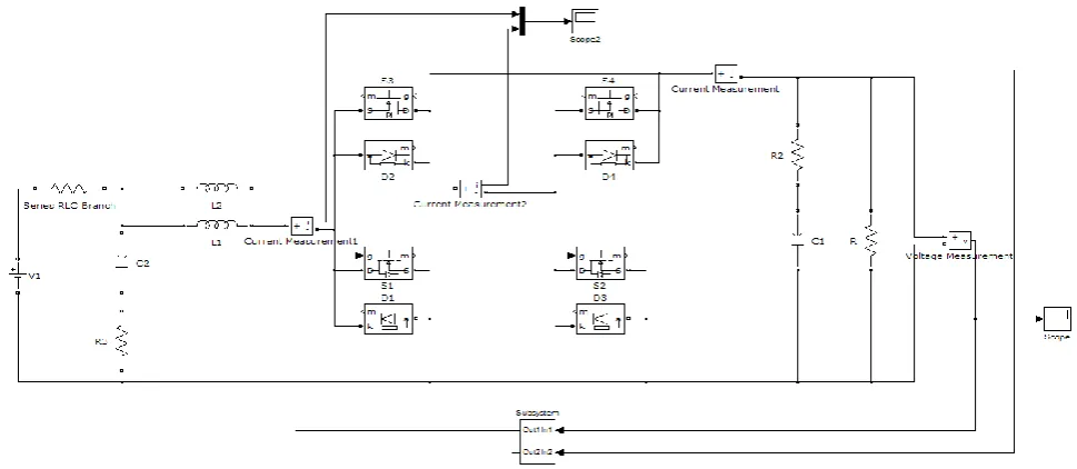
SIMULATION RESULTS ANALYSIS In order to verify the effectiveness of the controller, the boost model of two phase interleaved bidirectional DC-DC converter is established by using Fuzzytoolbox and “SimPowerSystems”toolbox in Matlab/simulink. Figure 4 is the Boost model simulation model.
© Ideal True Scholar (2016) (ISSN: 2067-7720)
http://ijeas.truescholar.org119 Fig. 5 Control subsystem simulation model
In figure 5, the control subsystem will use a fuzzy PID control voltage loop and two PI control current loop structure. After regulator adjusting voltage outer loop, the output voltage will be the current inner ring of the given value compared with the inductance of the converter current value, so as to control the output voltage pulse.
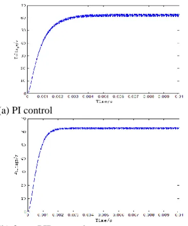
(a) PI control
(b) fuzzy PID control
Fig. 6 Voltage output waveform under Boost mode
Figure 6 is the simulation output voltage oscillogram of PI control and fuzzy PID control in Boost mode. It can be seen that the output voltage ripple of the bidirectional DC-DC converter is improved after fuzzy PID compensation, and the output voltage response speed is improved, the steady-state error is negligible.
In order to simulate the case of sudden start and acceleration of hybrid electric vehicle, it can be realized by using the load. t=0.005s, suddenly reduce load, used to simulate the vehicle speed running. The simulation results as shown in figure 7, when the system uses fuzzy PID control, the amplitude change
of the output voltage is small, and equilibrium is reached within a relatively short time, shows that the fuzzy PID control system has the characteristics of stability and fast dynamic response.
(a) PI control
(b) fuzzy PID control
Fig. 7 Output voltage waveform when the load is reduced under Boost mode
CONCLUSION
The paper takes the Boost converter as an example , achieves the design of a fuzzy PID controller, and
accomplishes matlab simulation verification
experiment. Experimental results shows: outer voltage loop adopts fuzzy PID control have solved the problem of nonlinear system. Compared with the traditional PI control, the fuzzy PID control of the outer voltage loop can effectively improve the response speed of the two phase interleaved bidirectional DC-DC converter, and reduce the output voltage ripple.
ACKNOWLEDGMENTS
Ideal Journal of Engineering and Applied Sciences (ISSN: 2067-7720) 2(3):119-123 Bidirectional Dc-Dc Converter With Outer Loop Voltage Based On Fuzzy PID Control
123 BSQD12023, and science and technology support program of Hubei Province, No.2014BAA135.
REFERENCES
Zhao, Yue, W. Qiao, and D. Ha. "A Sliding-Mode Duty-Ratio Controller for DC/DC Buck Converters With Constant Power Loads." IEEE Transactions on
Industry Applications, vol. 50, April2014, pp.
1448-1458.
Zhang, Ju, Z. Z. Xie, and G. L. Yang. "Mixed logical dynamical modeling and constrained optimal PWM control of DC/DC converters." Electric Machines &
Control, vol. 16, April2012, pp. 106-112.
Sun W, Lin P, Ye L U, et al. “Control Design of a Bi-directional DC/DC Converter for Electric Vehicle”. Power Electronics, Vol. 46,July 2012, pp. 40-42. Utkin V. “Sliding mode control of DC/DC converters”. Journal of the Franklin Institute, vol. 350, October 2013, pp. 2146-2165.
Liu Y. “Research on Nonlinear Control Strata gives for PWMDC-DC Converters”. Electro technical Journal, vol. 10, April2003. pp. 34-36.
Comparative D, Harmonic I, Ming B C, et al. “Analysis of the inductor current ripple in inter leaved bi-directional DC-DC power converters”. Relay, Vol. 35, February 2007, pp. 53-57.
Wang M Y, Deng X E. “Study on multiple soft-switching bidirectional DC/DC converter for electric vehicle”. Power Supply Technology and Its Application, vol. 37,May 2011, pp. 68-71.
Sato Y, Ishizuka T, Nezu K, et al. “A new control strategy for voltage-type PWM rectifiers to realize zero steady-state control error in input current”. Industry Applications IEEE Transactions on, vol. 34, May 1998, pp. 480-486.
Sato Y, Kataoka T.“State feedback control of
current-type PWM AC-to-DC converters”. IEEE
Transactions on Industry Applications, vol. 29, June 1993, pp. 1090-1097.
Zhu X. “Simulation Study on the Fuzzy Self-adapting PID Controller Design”. Journal of Convergence Information Technology, vol.8, April 2013, pp. 708-710.
Yang S Y, Guo-Lin X U. “Comparison and Composite of Fuzzy Control and PID Control”. Techniques of Automation & Applications, vol. 11, June 2011,pp. 21-25.