e- ISSN: 2278-067X, p-ISSN: 2278-800X, www.ijerd.com
Volume 14, Issue 5 (May Ver. II 2018), PP.54-60
Direct Torque Control of Induction Motor Using Space Vector
Modulation
Dhanamjaya Rao
1, Nagulapati Kiran
2 1ANITS, Assistant Professor, EEE Department.
2 ANITS, Assistant Professor, EEE Department.
Corresponding Author: Dhanamjaya Rao
ABSTRACT: - In this study, direct torque control of induction motor is evaluated based on space vector modulation. DTC is a method to control machine with utilizing torque and flux of motor controlled. The torque and current ripple occurred in the conventional DTC. Reason of undesired torque and current ripple is low number of voltage vectors applied to the motor controlled by the conventional DTC technique. SVMDTC is a technique to reduce the ripple. SVM techniques have several advantages that are offering better DC bus utilization, lower torque ripple, lower total harmonic distortion in the AC motor current, lower switching loss, and easier to implement in the digital systems. Simulation results from the classical and improved DTC are presented and compared. Result shows that the torque, flux linkage and stator current ripple are decreased with the improved DTC.
KEYWORDS:- DTC, SVPWM, Torque and Current ripple, Hysteresis comparator, DTC-SVM
--- Date of Submission: 21-05-2018 Date of acceptance: 05-06-2018
---I INTRODUCTION
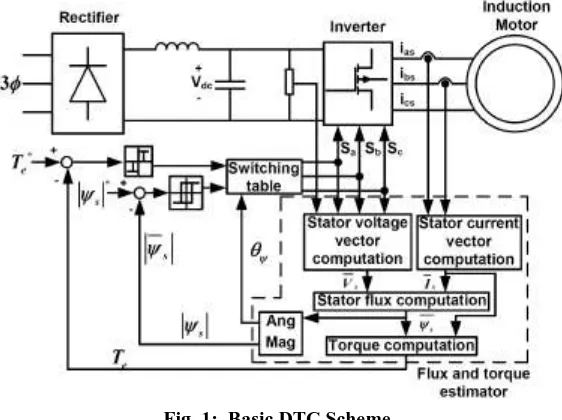
This Induction Motors (IMs) are widely used in high performance drives. Its history is very extensive and also control is important in applications. There are many IMs in a number of industrial, commercial and domestic applications of variable speed drives. Since IMs demands well control performances: precise and quick torque and flux response, large torque at low speed, wide speed range, the drive control system is the most sensitive point of IMs [1]. DTC is method to control machine with utilizing torque and flux of motor controlled. The basic DTC scheme consists of two comparators having different features, switching table, Voltage Source Inverter (VSI), flux and torque estimation block and IM.
Like a every control method has some advantages and disadvantages, DTC method has too. Some of the advantages are lower parameters dependency, making the system more robust and easier implements and the disadvantages are difficult to control flux and torque at low speed, current and torque distortion during the change of the sector in d-q plane, variable switching frequency, a high sampling frequency needed for digital implementation of hysteresis controllers, high torque ripple. The torque ripple generates noise and vibrations, causes errors in sensor less motor drives, and associated current ripples are in turn responsible for the EMI. The reason of the high current and torque ripple in DTC is the presence of hysteresis comparators together the limited number of available voltage vectors [2]. To reduce the torque ripple, the stator flux vector change, which is demanded to compensate the torque and flux errors, determination should be done and also any voltage vector should be produced by the control mechanism. If a higher number of voltage vectors than those used in conventional DTC is used, the favourable motor control can be obtained. Because of complexity of power and control circuit, this approach is not satisfactory for low or medium power applications. One of the methods to increase the number of available vectors is an on-line modulation between active and null vectors [2].
In order to overcome the problem, the SVM-DTC and DSVM-DTC methodologies were proposed [3]. The basis of the SVM-DTC methodology is the calculation of the required voltage space vector to compensate the flux and torque errors exactly by using a predictive technique and then its generation using the SVM at each sample period [3]. There are different SVM techniques, which are Direct-Reverse SVM, Direct- Direct SVM, Direct-Direct with Vnull=[000], Direct-Direct with Vnull=[111] in industry applications [4]. The choice of the SVM technique to be used will depend on the optimization criteria under consideration, whether it is the torque/current ripple, the harmonic losses or the switching losses.
II DIRECTTORQUECONTROL
estimated by integrating the stator voltages. Torque is estimated as a cross product of estimated stator flux linkage vector and measured motor current vector. The estimated flux magnitude and torque are then compared with their reference values. If either the estimated flux or torque deviates from the reference more than allowed tolerance, the transistors of the variable frequency drive are turned off and on in such a way that the flux and torque will return in their tolerance bands as fast as possible. Thus direct torque control is one form of the hysteresis or bang-bang control.
Fig. 1: Basic DTC Scheme
Torque and flux can be changed very fast by changing the references. The step response has no overshoot. No coordinate transforms are needed, all calculations are done in stationary coordinate system. No separate modulator is needed, the hysteresis control defines the switch control signals directly. There are no PI current controllers. Thus no tuning of the control is required. The switching frequency of the transistors is not constant. However, by controlling the width of the tolerance bands the average switching frequency can be kept roughly at its reference value. This also keeps the current and torque ripple small. Thus the torque and current ripple are of the same magnitude than with vector controlled drives with the same switching frequency. Due to the hysteresis control the switching process is random by nature. Thus there are no peaks in the current spectrum. This further means that the audible noise of the machine is low. The intermediate DC circuit's voltage variation is automatically taken into account in the algorithm (in voltage integration). Thus no problems exist due to dc voltage ripple (aliasing) or dc voltage transients. Synchronization to rotating machine is straightforward due to the fast control; Just make the torque reference zero and start the inverter. The flux will be identified by the first current pulse. Digital control equipment has to be very fast in order to be able to prevent the flux and torque from deviating far from the tolerance bands. Typically the control algorithm has to be performed with 10 - 30 microseconds or shorter intervals. However, the amount of calculations required is small due to the simplicity of the algorithm. The current and voltage measuring devices have to be high quality ones without noise and low-pass filtering, because noise and slow response ruins the hysteresis control. In higher speeds the method is not sensitive to any motor parameters. However, at low speeds the error in stator resistance used in stator flux estimation becomes critical.
The direct torque method performs very well even without speed sensors. However, the flux estimation is usually based on the integration of the motor phase voltages. Due to the inevitable errors in the voltage measurement and stator resistance estimate the integrals tend to become erroneous at low speed. Thus it is not possible to control the motor if the output frequency of the variable frequency drive is zero. However, by careful design of the control system it is possible to have the minimum frequency in the range 0.5 Hz to 1 Hz that is enough to make possible to start an induction motor with full torque from a standstill situation. A reversal of the rotation direction is possible too if the speed is passing through the zero range rapidly enough to prevent excessive flux estimate deviation. If continuous operation at low speeds including zero frequency operation is required, a speed or position sensor can be added to the DTC system. With the sensor high accuracy of the torque and speed control can be maintained in the whole speed range.
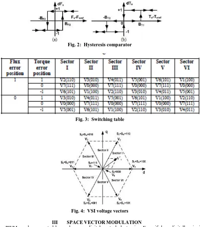
Two stator currents (iSA and iSB) and DC-bus voltage VDC are sampled. d-q components of stator voltage and current space vectors in the stationary reference frame and also magnitude of the stator flux and electric torque are calculated as shown below. The magnitude of stator flux and electric torque calculated are compared with their reference values in the hysteresis comparators shown in Figure 2 and then the outputs of the comparators are fed to a switching table to select an appropriate inverter voltage vector. The switching table shown as Table I determine the voltage vector to apply based on the position of the stator flux and the required changes in stator flux magnitude and torque [8]. The selected voltage vector will be applied to the induction motor at the end of the sample time. In VSI, there are six equally spaced voltage vectors having the same amplitude and two zero voltage vectors. VSI voltage vectors are shown in Figure.
In DTC, torque and flux are controlled independently by selecting the optimum voltage space vector for entire switching period and the errors are maintained with in the hysteresis band [9]. In conventional DTC, only one vector is applied for the entire sampling period. So for small errors, the motor torque may exceed the upper\lower torque limit. Instead by using more than one vector with in the sampling period torque ripple can be reduced. The slip frequency can be controlled precisely by inserting zero vectors [10]. For the small the hysteresis band, frequency of operation of PWM inverter could be very high. The switching frequency always varies according to the width of hysteresis band.
Fig. 2: Hysteresis comparator
Fig. 3: Switching table
Fig. 4: VSI voltage vectors
III SPACEVECTORMODULATION
Modulation this calculation process is simplified. As it is simplified, less computing time is required, and therefore better performance can be obtained.
.
Fig. 5: Three phase Inverter
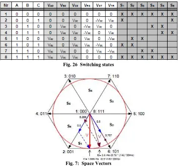
As we have 3 switches (A, B and C) there are 8 different switching combinations. For example A on, B off, C on. We can analyse for all switching combinations the phase-phase voltages on the primary winding of the transformer. If we look to the voltages that need to be generated between each leg (fig 8) we can split that into 8 different „‟spaces‟‟,S1, S2 etc. For each space we can use the table to define which switching states the inverter must use to obtain those voltages. For example for period („‟space‟‟) S1, we see that the VRS is positive, VST is negative and VTR is positive. Besides the fact that these voltages are positive or negative they also reach a point where they are zero. From the table it can be read that in period S1 the inverter needs to be switching between state Nr. 1, 2, 8 and 6.
Fig. 26 Switching states
Fig. 7: Space Vectors
Vector Modulation can be implemented by means of DSPs (Digital Signal Processors). These are microprocessors which are suitable to process analogue signals. DSPs provide fast sampling rates which make them ideally suited to UPS control. By using an isolation transformer on the output of the inverter, special modulation techniques can be applied. The modulation index can be increased with 15% by adding a 3rd harmonic (150Hz in case of 50Hz output) to the signal on each leg of the transformer. As the transformer is in dye configuration, this 3rd harmonic will not appear on the output voltage. This optimisation is not possible in transformer less inverters (UPS).
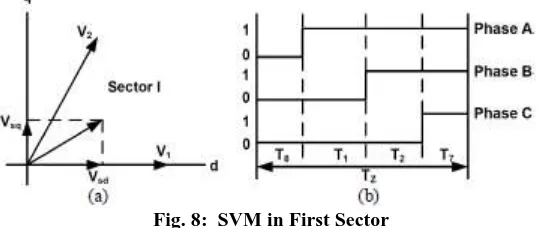
SVM, based on the switching between two adjacent boundary active vectors and a zero vector during one switching period, Tz, and for a given reference voltage vector in the first sector (0-60o) is shown in Figure.
Fig. 8: SVM in First Sector
The switching times can be calculated using the following equations:
VSVsd jVsq
where the vectors Vsd and Vsq are obtained from the appropriate voltage vectors for any given sector.
IV SIMULATIONRESULTS
The SIMULINK Model of DTC of Induction Motor using Space Vector Pulse Width Modulation is shown.
Fig. 9: SIMULINK model of DTC-SVM
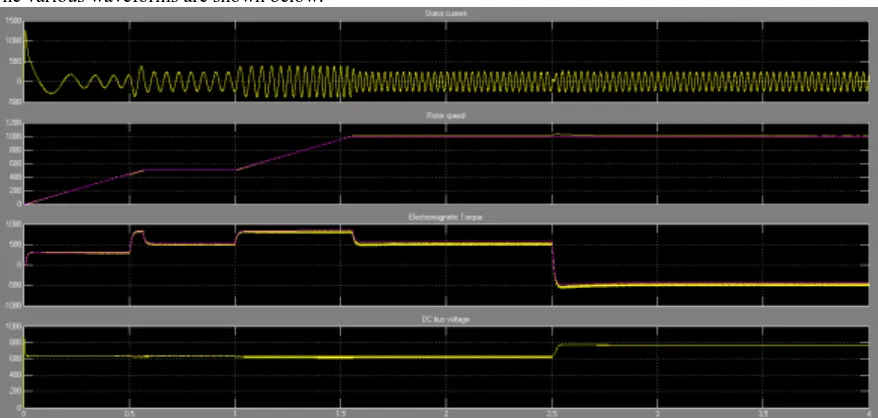
The various waveforms are shown below:
Fig. 10: Waveforms of DTC-SVM
V CONCLUSION
In classical DTC, as the torque ripple is maintained within hysteresis band, switching frequency changes with speed. Moreover, the torque ripple is important problem at low speed. So using constant switching frequency a desired torque ripple can be achieved at low speeds where it really matters. The torque ripple for this SVM-DTC is significantly improved and switching frequency is maintained constant. Numerical simulations have been carried out showing the advantages of the SVM-DTC method with respect to the conventional DTC.
REFERENCES
[1]. S. Jianguo and C. Quanshi, “Research of electric vehicle IM controller based on space vector modulation direct torque control,”
Proceedings of the Eighth International Conference on Electrical Machines and systems, ICEMS 2005, vol. 2, pp. 1617-1620, 2005.
[2]. D. Ocean, L. Romeral, J.A. Ortega, J. Cusido, and A. Garcia, “Discrete pace vector modulation applied on a PMSM motor,” 12th
[3]. H.R. Keyhani, M.R. Zolghadri, and A. Homaifar, “An extended and mproved discrete space vector modulation direct torque control for nduction motors,” 35th Annual IEEE Power Electronics Specialists onference, Germany, pp. 3414-3420, 2004.
[4]. R.H. Ahmad, G.G. Karady, T.D. Blake, and P. Pinewski, “Comparison f space vector modulation techniques based on performance
indexes nd hardware implementation,” 23rd International Conference on ndustrial Electronics, Control and Instrumentation, IECON 97, vol. 2, p. 682-687, 1997.
[5]. I. Takashi and T. Noguchi, “A new quick-response and high-efficiency ontrol of an induction motor,” IEEE Trans. Industry
Applications, vol. A-22, no.5, pp. 820-827, 1986.
[6]. M. Depenbrock, “Direct self control (DSC) of inverter-fed induction achines,” IEEE Trans. Power Electronics, vol. 3, no. 4, pp. 420-429, 988.
[7]. M. Jin, J. Qiu, C. Shi, and R. Lin, “A fuzzy DTC method with a SVM efuzzification to permanent magnet synchronous machine,”
The 30th nnual Conference of the IEEE Industrial Electronics Society, Korea p. 3196-3199, 2004.
[8]. M. Vasudevan and R. Arumugam, “New direct torque control scheme of nduction motor for electric vehicles,” 5th Asian Control
Conference, pp. 377-1383, 2004.
[9]. A. Kumar, B.G. Fernandes, and K. Chatterjee, “Simplified SVPWMDTC f 3-phase induction motor using the concept of imaginary
witching times,” The 30th Annual Conference of the IEEE Industrial lectronics Society, Korea, pp. 341-346, 2004.
[10]. U. Senthil and B.G. Fernandes, “Hybrid space vector pulse width odulation based direct torque controlled induction motor drive,”
IEEE 4th Annual Power Electronics Specialist Conference, PESC‟02, vol. 3, p. 1112-1117, 2003.
[11]. L. Chen, K.L. Fang, and Z.F. Hu, “A scheme of fuzzy direct torque ontrol for induction machine,” Proceedings of the Fourth International onference on Machine Learning and Cybernetics, Guangzhou, pp. 03-807, 2005.
[12]. H.I. Okumus, “Improved direct torque control of induction machine rives,” PhD Thesis, University of Bristol, UK, July 2001.