UNIVERSITI TEKNIKAL MALAYSIA MELAKA
OPTIMIZATION OF VISION-GUIDED MOBILE ROBOT
NAVIGATION
This report submitted in accordance with requirement of the Universiti Teknikal Malaysia Melaka (UTeM) for the Bachelor Degree of Manufacturing Engineering
(Robotics & Automation) with Honours.
by
OOI YEE KHAI B051310037 920726-07-5581
DECLARATION
I hereby, declared this report entitled “Optimization of Vision-Guided Mobile Robot Navigation” is the results of my own research except as cited in references.
APPROVAL
This report is submitted to the Faculty of Manufacturing Engineering of UTeM as a partial fulfillment of the requirements for the degree of Bachelor of Manufacturing Engineering (Robotics & Automation) with Honours. The member of the supervisory committee is as follow:
(Signature of Principal Supervisor) ... (Official Stamp of Principal Supervisor)
ABSTRAK
Navigasi robot mudah alih sentiasa memerlukan sensor seperti sensor ultrasonik, sensor inframerah, dan sensor laser untuk mengesan objek dan perubahan fizikal pada persekitaran dunia. Walau bagaimanapun, isyarat pemancar sensor ini akan terganggu apabila terdapat gangguan gelombong berlaku di sekeliling kawasan tersebut. Ini akan menyebabkan kekurangan tepat isyarat dan seterusnya data yang silap diterima oleh pengawal robot. Sensor penglihatan iaitu sensor yang berasaskan kamera dipilih untuk membina sistem visi kepada robot mudah alih untuk tujuan navigasi. Ini adalah disebabkan data yang diperolehi oleh sensor kamera adalah dalam bentuk imej oleh itu kejadian gangguan gelombong akan menjadi lebih sukar. Kamera Pixy dipasang pada robot mudah alih Arduino kemudian sistem visi itu direka dengan menggunakan pengaturcaraan Arduino IDE untuk mengintegrasikan modul kamera dengan modul robot. Sistem visi ini dicipta untuk melaksanakan navigasi dan pengelakan halangan melalui beberapa algoritma seperti pemprosesan imej, pengekstrakan data, dan membuat pengiraan. Robot mudah alih bersepadu sistem visi ini dapat mengikuti garis untuk mengemudi dan menukar laluannya untuk mengelakkan halangan. Masa yang diambil oleh robot mudah alih bersepadu sistem visi ini untuk mengemudi dengan mengikuti garisan adalah lebih pendek jika dibandingkan dengan robot mudah alih yang menggunakan sensor inframerah dalam mengikuti garisan yang sama. Sistem visi ini tepat dalam mengesan perbezaan warna semasa melakukan penukaran laluan. Ia juga mempunyai ketekalan tinggi dalam mengulangi laluan yang sama.
ABSTRACT
The navigation of mobile robot always includes sensors like ultrasonic sensor, infrared sensor, and laser rangefinder to detect objects and physical changes at the world environment. However, the transmitting signal of these sensors will be interrupted when there is disturbance occurs at the surrounding environment. This will cause to the inaccurate signal and data to be received by the controller. Vision sensor which is a camera-based sensor is more preferable and selected to be developed as the vision system to the mobile robot for navigation. This is because of the data obtained by a camera sensor is of image form and thus occurrence of disturbance to the data transferring will be more difficult. A Pixy colour camera is installed on an Arduino mobile robot and the vision system is developed through programming using Arduino IDE to integrate the camera module with the robot module. The vision system is created to perform navigation and obstacle avoidance via several algorithms such as image processing, data extraction, and computation. The integrated vision-guided mobile robot able to follow line to navigate and switch path to avoid obstacle. The time taken for the vision-guided mobile robot in line following is much shorter when compared to mobile robot that utilizes infrared sensor in following the same path. The vision system is precise in detecting the colour difference during path switching. It also has high consistency in repeating the same path.
ACKNOWLEDGEMENT
I would like to thank my main supervisor, En Shariman Bin Abdullah, for giving me this opportunity to do final year project with him. Hereby, I also would like to express my deepest appreciation to my co-supervisor, Dr Muhammad Hafidz Fazli Md Fauadi. He never hesitate to provide me with advice and guidance whenever I face problems throughout the entire project. I am thankful for his patience and help. Without his knowledge and guidance, this dissertation would not have been successful.
In addition, a thank you to the coordinators of final year project who selflessly share their knowledge, guidance, and encouragement. Also, I would like to thank laboratory assistant, En. Muhamad Asari Bin Abdul Rahim for his kindness in providing me the environment and materials for conducting experiments and tests. Moreover, I would like to express my deepest appreciation to lecturer, En. Shamsul Fakhar Bin Abd Gani, for teaching and guiding me in the program coding writing. Without his help, the project wouldn't be accomplished smoothly as planned.
I would like to thank my course mates for giving me support, patience, and encouragement. Last but not least, I would like to thank my family for their unconditionally love and support.
TABLE OF CONTENT
Abstract i
Abstrak ii
Acknowledgement iii
Table of Content iv
List of Tables vi
List of Figures vii
List of Abbreviations ix
1. INTRODUCTION 1
1.1 Project Background 1
1.2 Problem Statement 3
1.3 Objectives 5
1.4 Scope 5
2. LITERATURE REVIEW 6
2.1 Mobile Robot Sensor 6
2.1.1 Sensors for Dead Reckoning 6
2.1.2 Map Positioning Sensors 8
2.2 Vision System Navigation 9
2.2.1 Camera Calibration 11
2.2.2 Image Processing 15
2.2.2.1 Image Acquisition 15
2.1.2.2 Image Analysis 17
2.2.3 Map and Navigation 18
2.2.4 Monocular vs Stereo Vision System 20
2.3 Mobile Robot 21
2.3.1 Existing Mobile Robot Platforms 21
2.3.2 Arduino Platform 23
3. METHODOLOGY 25
3.1 Mobile Robot Development 27
3.1.1 Hardware Components 27
3.1.1.1 Arduino Robot 27
3.1.1.2 CMUcam5 30
3.1.2 Software 32
3.1.2.1 Arduino Software (IDE) 32
3.1.2.2 PixyMon 34
3.2 Project Implementation 35
3.2.1 Hardware Module 35
3.2.2 Software Coding 36
3.2.3 Camera Calibration 37
3.3 Colour Image Processing 39
3.3.1 Colour Filtering Algorithm 39
3.4 Experimental Test 41
3.4.1 Line Following Trajectory 41
3.4.2 Path Switching Trajectory 42
4. RESULT & DISCUSSION 43
4.1 Hardware Product 43
4.2 Arduino Program Coding 44
4.3 Line Following (Navigation) 47
4.3.1 Consistency 50
4.3.2 Comparison To Arduino Robot Line Following 52
4.4 Path Switching (Obstacle Avoidance) 55
4.4.1 Precision 57
4.5 Sustainable Design Elements 58
5. CONCLUSION & RECOMMENDATIONS 59
5.1 Conclusion 59
5.2 Recommendations 60
REFERENCES 61
LIST OF TABLES
3.1 Arduino Robot's Control Board summary 28
3.2 Arduino Robot's Motor Board summary 29
3.3 CMUcam5 specifications 31
3.4 Example of Arduino coding 37
4.1 Final Arduino coding 45
4.2 Robot's availability to return 50
4.3 Comparison between infrared sensor and vision sensor 53
4.4 Response time of path switching 57
LIST OF FIGURES
1.1 Robot control mechanism 1
1.2 Ultrasonic sensor commonly used in mobile robot 2 1.3 Sandia Robot Rodeo for military use in bomb defusing 3
2.1 The A and B channels' pulse trains phase relationship
of incremental optical encoder 7
2.2 Absolute optical encoder 7
2.3 SCARF block diagram 9
2.4 A cascade control system for target trajectory 10
2.5 Flow-chart of the whole system 11
2.6 The calibration phase one reference system is robot independent 13 2.7 The ground reference system to the reference system of robot 14
2.8 Fundamental diagram of axis 16
2.9 Image analysis example 18
2.10 The map part constructed from Figure 2.9 19
2.11 Stereo vision system 20
2.12 Palm Pilot Robot Kit 22
2.13 Cye platform with webcam 22
2.14 ER1 kit 23
2.15 Roomba Create 23
2.16 Arduino UNO Board 24
3.1(a) Project flow chart 25
3.1(b) Project flow chart 26
3.2 Arduino Robot's Control Board configuration 28
3.3 Arduino Robot's Motor Board configuration 29
3.4 CMUcam5 31
3.5 Example of IDE sketch 33
3.6 Pixymon display 34
3.7 Hardware modules linkage 35
3.8(a) Pixy sight of view after 60o inclined 36
3.8(b) Pixy 60o inclination 36
3.9(a) Image of calibration object captured 38
3.9(b) Colour region of object selected as colour signature 38
3.10 Colour Image Processing Algorithm 39
3.11 Colour region recognized as a blog 40
3.12 Line following trajectory 41
3.13 Path switching trajectory 42
4.1 (a) Side view; (b) front view; (c) 3D view; and
(d) top view of the vision guided mobile robot 43 4.2 (a) Robot begins; (b & c) moves forward;
(d & e) rotates at end of line; (f & g) moves back to the initial point 47 4.3 Pie chart showing the percentage of the availability 51 4.4 (a &b) Robot moves forward; (c) out of the track;
(d) turns back to the track; (e) moves forward again 52 4.5 (a) Robot begins; (b) moves forward; (c) rotates;
(d & e) switches path; (f) moves forward again 55
LIST OF ABBREVIATIONS
2D - Two Dimensional
3D - Three Dimensional
A - Ampere
AC - Alternative Current
AGV - Automated Guided Vehicle
B - Byte
CDC - Communications Device Class
COM - Communication
DC - Direct Current
EEPROM - Electrically Erasable Programmable Read-Only Memory FAT - File Allocation Table
FM - Frequency-modulated
fps - Frame per second
GPS - Global Positioning System GTFT - Thin Film Transistor
H - Height
Hz - Hertz
IDE - Integrated development environment
I/O - Input/Output
IR - Infrared
K - Kilo
L - Length
LCD - Liquid Crystal Display LED - Light-Emitting Diode
m - Mili
M - Mega
MATLAB - Matrix Laboratory
PDA - Personal Digital Assistant PWM - Pulse Width Modulation RGB - Red, Green, Blue
ROI - Region of Interest
SCARF - Supervised Classification Applied to Road Following
SD - Secure Digital
SPI - Service Provider Interface SRAM - Static Random Access Memory TOF - Time of Flight
UART - Universal Asynchronous Receiver Transmitter USB - Universal Serial Bus
V - Volt
CHAPTER 1
INTRODUCTION
1.1 Project Background
Mobile robot is a locomotive machine with the capability to move from one place to another. The capability is so called navigation. Navigation is the fundamental concept for every robot to be mobile. There is two basic types of navigation. The first one is local navigation that deals with environmental situation within low range of distance in order to avoid obstacle or collision occurs. The another named global navigation is the localization of the robot on a larger scale environment using a global maps or pre-specified topological maps regarding to the robot's initial position.
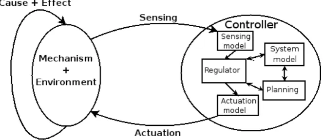
[image:14.595.156.488.605.749.2]Local navigation of mobile robot is always in associate with the sensors to give signal about object detection on the outer environment in order to locate itself at that environment and to generate a map of the corresponding environment. Then mobile robot has a controller to receive the signal and to give command to the actuator that moves the wheels so that the robot can navigate from one point to another as depicted in the Figure 1.1 below.
Figure 1.1: Robot control mechanism
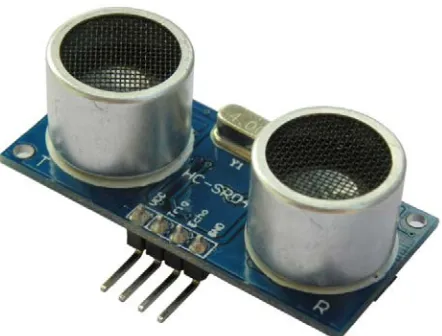
Sensors play an important role on the mobility of robot. Non-contact sensor is the group of sensor commonly used on mobile robot to detect the presence and predict the distance of the object around the robot. The sensors that usually found on navigation robot are of several types such as proximity sensor, infrared sensor, photoelectric sensor, ultrasonic sensor as shown in Figure 1.2 below, and others. However, a vision-based sensor is now a rapidly developing technique in the field of autonomous mobile robot. It is still freshly utilized on mobile robot due to the increased difficulty on its integration with controller with the necessary in calibration of the sensor via programming. It is also currently less preferable due to its high implementation cost.
Figure 1.2: Ultrasonic sensor commonly used in mobile robot
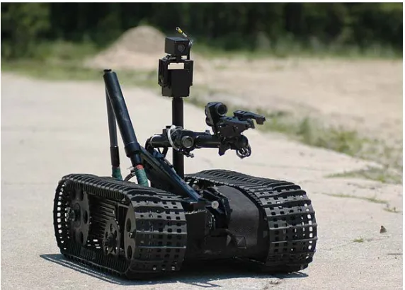
Mobile robots are designed to perform certain works or tasks that previously done by human. Mobile robots can be basically categorized into indoor mobile robot and outdoor mobile robot depends on the type of business functions. Due to its capability, they are very expedient in domestic, medical, military, and space purpose. Indoor robots are usually involved in floor cleaning, material handling, and industrial applications which involve dangerous condition or hazardous environment. On the other hand, human use outdoor robots for patrol, surveillance, dangerous tasks like bomb defusing in military, and exploring planets and space functions. All of the tasks require the mobile robots to possess an accurate autonomous navigation system. Figure 1.3 depicts the robot for military use in bomb defusing. For outdoor navigation, GPS is very useful in localization and other sensors like laser range finders will be used to address the path planning after the geographical position of
the robot on planet is identified. While for indoor navigation, cameras and laser scanners are commonly used to create the topological map so that the robots would able to avoid collision upon obstacles.
Figure 1.3: Sandia Robot Rodeo for military use in bomb defusing (http://www.sandia.gov/)
Currently, Arduino mobile robot is very common in the field of robotics for beginner usage due to its simple design, user friendly, and ease of control and program with its widespread open source programming language. Arduino mobile robot is normally two-wheel-drive or four-wheel-drive for its navigating purpose. Moreover, its hardware components can be customized by adding on variety types of sensor and electronics depending to the user's application. In addition, the cost of Arduino mobile robot is definitely lower compared to other mobile robots in the market. Thus, it is very suitable to be used for research and development project.
1.2 Problem Statement
A common mobile robot utilizes infrared, laser, or ultrasonic sensors for collecting data for its path planning. However, this kind of sensors only give data in a imperceptible way. The algorithm involves mathematical computation of the input data perceives from the time of receiving light radiation or sound signal transmitted from a source mounted on the robot. The sensor system sometimes could be inaccurate due to interruption of the traveling signal caused by disturbance from the
surroundings environment which will result to incorrect data reception. Therefore, a vision sensor is an alternative to replace the ordinary sensors applied in mobile robot. The image captured by camera is a visualizing data which will be perceived by the processing unit and analyzed with algorithms to interpret it into usable information for path planning of the robot.
A monocular vision system consist of single camera as the vision sensor. The implementation of monocular vision system on mobile robot would require the pre-calibration of the camera with the aid of a pre-calibration object consists of similarity in certain features such as color or shape with the object to be detected. Then, in order to integrate the vision system with the robot motion system, programming is a must to create algorithms for computing the value of motion parameters corresponding to the data like pixel coordinates obtained from the input image. Path planning will be decided regarding to the information extracted from the interpreted data. The motion parameter values are required to sent as a signal command to the actuators of the robot for its corresponding movement to achieve the goal.
The vision-guided navigation system can be a greater accuracy and precision system for mobile robot to do its tasks. The monocular vision system mobile robot is ideally to be applied in indoor environment. The obstacle avoiding feature of the mobile robot is very useful for multiple applications such as path following and material handling. In this research project, path following and static obstacle avoidance would be the function of the navigation system implies at. Thus, the capability to avoid obstacle without collision and navigate through the indoor environment within short period are the aims to be achieved by the navigation system.
1.3 Objectives
The objectives of the project are:
• to investigate the camera-based navigation system for mobile robot;
• to design and develop monocular vision system on a mobile robot through
calibration of camera and develop program for camera-robot integration; and • to test the vision-guided mobile robot for navigation and obstacle avoidance.
1.4 Scope
The project consists of Arduino mobile robot as the selected type of mobile robot and Pixy camera as the main sensor of the robot. The navigation robot would be implied with monocular vision system rather than stereo vision system due to higher complexity and difficulty in implementation. Color feature is used for the detection algorithm instead of shape or other features. Then, Arduino IDE which is an open source code software is used for the programming of the navigation system including calibration and integration processes. Furthermore, the experimental mobile robot will be tested and studied for indoor environment purpose rather than outdoor application. The robot will be examined for avoiding obstacles and navigating through the surrounding indoor environment.
CHAPTER 2
LITERATURE REVIEW
2.1 Mobile Robot Sensor
Leonard and Durrant-Whyte (1991) conclude that navigation of mobile robot is related with only three simple questions which are : 1)"Where am I?," 2)"Where am I going?," and 3)"How should I get there?." In order to answer the first question, sensors play a vital role for robot positioning in the environment. The robot positioning includes dead reckoning and map positioning as two types of positioning method.
2.1.1 Sensors for Dead Reckoning
According to Dunlap and Shufeldt (1972), dead reckoning is a term used in ancient time during sailing which refers to determination of the current location of a ship by referencing to its previous position through simple mathematical calculation with given the velocity value over a given period of time. The word "dead reckoning" is now always known as "odometry" to be implied to the vehicle displacement along a path or variation of wheeled locomotion. The most popular sensor nowadays for dead reckoning is the optical encoder which can be instantaneously coupled to wheel axles or motor. Optical encoder is like a small size proximity sensor that uses a rotating intermediate disk with coded opaque or transparent pattern to continually interrupt an emitted beam of light that aiming at a matched photodetector. Optical encoder consists of two types which are the absolute one and the incremental one.
i. Incremental Optical Encoder
[image:20.595.135.502.264.358.2]Nickson (1985) claims that this type of sensor is suitable to measure the rotational velocity and to infer the relative location of medium-to-high-speed control systems, but at very low speed will generate quantization errors that cause to noise and stability problems. Tachometer encoder is the simplest type of incremental encoder that generates a particular amount of square-wave or sine- pulses in each of every revolution of the shaft by using its mechanical light chopper as shown in Figure 2.1 below. The resolution of the unit will be higher as increasing the pulses.
Figure 2.1: The A and B channels' pulse trains phase relationship of incremental optical encoder (Nickson [1985])
ii. Absolute Optical Encoder
This type of sensor is commonly used for slower rotational task when there is no tolerance for power interruption to have potential loss of reference but positional information is needed. The increase in the size of disk will decrease the shock and vibration tolerance. Agent (1991) proves the rule that the resolution will be doubled with each additional encoder track and the cost will be quadrupled. The Figure 2.2 depicts the rotating encoder disk being emitted by a light beam traversing through the transparent and opaque parts across its coded pattern to specify the absolute angular position of the shaft.
Figure 2.2: Absolute optical encoder (Agent [1991])
[image:20.595.158.479.608.727.2]2.1.2 Map Positioning Sensors
The sensors utilized to build map are often related to distance measurement. The types of approaches for distance measurement are normally divided into three categories:
• The measure of pulse's time of flight (TOF) that uses a transmitter with
source of energy being emitted to an object that reflects the energy's echo to a receiver for distance calculation.
• The ranging technique on phase-shift measurement that uses uninterrupted
wave transmitting which is differ from short pulsed outputs in TOF method. • The frequency-modulated (FM) radar that somehow involves the phase-shift
measurement technique too.
The sensors with first approach which are using TOF measurement tend to be more popular and commonly used in mobile robot.
i. Ultrasonic Sensor
Ultrasonic sensor has come to be the most popular type of sensor being used in mobile robot nowadays especially for those navigate in indoor environment. The sensor is very useful in multiple applications like collision avoidance, position estimation, motion detection, and world modelling. Moreover, Hammond (1993) states that ultrasonic sensor has been used widely in exterior settings due to its availability in low-cost system and the ease of interface.
ii. Laser Rangefinder
Laser rangefinder can be called as lidar or laser radar too. The working principle is that a speedy sequence of short bursts emitting laser energy on a ranged object. Then the time for the energy to reflect from the object and return will be used for calculating the object distance by referring to the speed of light wave. Depkovich and Wolfe (1984) claim that the sensor's accuracy in early time is limited from 1 to 5 meters distance only. However, now it has greater accuracy and very useful in mobile robot navigation but is less cost effective compared to ultrasonic and infrared sensors.
2.2 Vision System Navigation
Chrisman and Thorpe (1993) claim that the navigation system of a mobile robot comprises of perception systems to detect surroundings, path planning systems to arrange the route, and motor control systems to activate the movement of robot body. For road navigation, no less than one recognition system has to detect the area of paths. While path planning system has to ensure the robot on its correct path and at the same time maintaining a strategic distance from any obstacles. SCARF, Supervised Classification Applied to Road Following, invented by them is a vision system using color to recognize difficult roads and junctions as depicted in Figure 2.3 below. The vision system when integrated with mobile robot is capable to navigate on improper roads and junctions that could consist of:
• no edge lines or lane painted on the road surface, • lowered road edges,
• road surface scars,
• sharp shadow conditions, and • no map information.
[image:22.595.222.403.522.723.2]However, SCARF has limitation on solving obstacle avoidance task. It is well performed on detecting difficult roads and intersections by using Bayesian classification without prior information of location and condition of the intersection.
Figure 2.3: SCARF block diagram (Chrisman and Thorpe [1993])
Saifizi et al. (2012) state that local navigation, for example, vision strategies are exceptionally compelling base in the shut extent navigation. Basically, the main considerations in utilizing image sensors and processing is its influence to the exactness of the navigation system. For navigating purpose, a mobile robot need to translate its sensing information into concentrate surroundings data so that its location can be identified. Then, the robot must choose the proper way to accomplish its goal. After that, the driving system of the mobile robot will be activated to reached its destination. Their research vision system has the purpose to recognize circle as landmark and determine distance and orientation from the target image for short ranged navigation. The system is more adaptable in indoor environment for local navigation via feature (circle) pursuing algorithm using fuzzy logic to generate target trajectory of the moving robot as depicted in Figure 2.4 below.
Figure 2.4: A cascade control system for target trajectory (Saifizi et al. [2012])
Giuseppina and Alberto (2002) prove that a single camera can take care of issues within indoor environment with modestly alterable framework as the mobile robot proceeds onward horizontal surface. This single camera vision capable to navigate mobile robot on an indoor floor while avoiding obstacle and people by using a little prior information, on board calculation, and without omni-directional vision as depicted in the Figure 2.5 below. The rest of the tasks are: map learning; route decision making and avoidance of collision with obstacle; and self-localization. The learning of map is a very much contemplated region, yet build of map utilizing monocular vision would give much benefits compared to other sensors that are higher reliable but higher cost either such as laser rangefinder. The ground image data can be changed into grip map, which consists of certainty value to determine whether there is obstacle on the floor.
Figure 2.5: Flow-chart of the whole system (Giuseppina and Alberto [2002])
2.2.1 Camera Calibration
Herbert (1989) claims that a calibration procedure should be developed to identify the compatibility between image coordinates and world coordinates. As the pin-hole model is usually selected to calculate the real coordinates in reference to the image coordinates using f, focal distance. The transform given by H matrix as:
(1)
start Image
acquisition
Analysis and floor search
same floor?
Map modification
Planning of the possible path
Path found?
move for a step the robot in the given
direction
New goal definition Yes
Yes
No
No
![Figure 2.1: The A and B channels' pulse trains phase relationship of incremental optical encoder (Nickson [1985])](https://thumb-us.123doks.com/thumbv2/123dok_us/136594.13738/20.595.158.479.608.727/figure-channels-trains-relationship-incremental-optical-encoder-nickson.webp)
![Figure 2.3: SCARF block diagram (Chrisman and Thorpe [1993])](https://thumb-us.123doks.com/thumbv2/123dok_us/136594.13738/22.595.222.403.522.723/figure-scarf-block-diagram-chrisman-thorpe.webp)
![Figure 2.4: A cascade control system for target trajectory (Saifizi et al. [2012])](https://thumb-us.123doks.com/thumbv2/123dok_us/136594.13738/23.595.163.473.344.466/figure-cascade-control-target-trajectory-saifizi-et-al.webp)
![Figure 2.5: Flow-chart of the whole system (Giuseppina and Alberto [2002])](https://thumb-us.123doks.com/thumbv2/123dok_us/136594.13738/24.595.151.474.72.490/figure-flow-chart-giuseppina-alberto.webp)
