SUPERVISOR ENDORSEMENT
“I hereby declared that I have read through this report entitle “Speed Control of Permanent Magnet Synchronous Motor Drive Using Fuzzy Logic Controller” and found that it has comply the partial fulfillment for awarding the degree of Bachelor of Electrical Engineering (Power Electronic and Drive).”
Signature : ………
Supervisor Name : Associates Professor Dr. Zulkifilie Bin Ibrahim
SPEED CONTROL OF PERMANENT MAGNET
SYNCHRONOUS MOTOR DRIVE USING FUZZY LOGIC CONTROLLER
CHANG TING WEI
A report submitted in partial fulfillment of the requirements for the degree of Bachelor in Electrical Engineering
Faculty of Electrical Engineering
UNIVERSITI TEKNIKAL MALAYSIA MELAKA
iii
DECLARATION
I declared that this report entitle “Speed Control of Permanent Magnet Synchronous Motor Drive Using Fuzzy Logic Controller” is the result of my own research except as cited in the references. The report has not been accepted for any degree and is not concurrently submitted in candidature of any other degree.
Signature : ………
Name : Chang Ting Wei
Date : ………
iv
DEDICATION
v
ACKNOWLEDGEMENT
I would like to take this opportunity to express my gratitude toward those authorities who support and give a helping hand to me for accomplish this final year project.
First and foremost, I would like to show my deepest gratitude to my supervisor, Associate Professor Dr. Zulkifilie Bin Ibrahim who assist, guide and teach me a lot throughout this whole process of accomplish the final year project. The valuable guidance, help, patience, advice and support from Associate Professor Dr. Zulkifilie Bin Ibrahim are significant in completing this final year project.
Next, I would like to thank to my beloved laboratory friends, Mrs. Raihana Binti Mustafa, Mrs. Nur Hidayah Binti Abu Khanipah and Mrs. Ayu Nurfatika Binti Abdul Mubin for their opinion, advice, assistance, encouragement and patience throughout this final year project. In addition, thousand thanks to Mrs. Raihana Binti Mustafa who help me a lot in giving a lot of advice and encouragement in the hardware implementation. Besides, I would also like to thank Mr. Sahril Bin Bahar, the laboratory technician who assist and gives opinion on my hardware experimental setup.
vi
ABSTRACT
vii
ABSTRAK
viii
TABLE OF CONTENT
CHAPTER TITLE PAGE
ACKNOWLEDGEMENT v
ABSTRACT vi
ABSTRAK vii
TABLE OF CONTENT viii
LIST OF TABLES xii
LIST OF FIGURES xiii
LIST OF ABBREVIATIONS xviii
LIST OF APPENDICES xix
1 INTRODUCTION 1
1.1 Research Background 1
1.2 Problem Statement 4
1.3 Objectives 5
1.4 Scope 5
1.5Expected Outcome 6 1.6 Report Outline 6
2 LITERATURE REVIEW 8
2.1 Introduction 8
2.2 Permanent Magnet Synchronous Motor (PMSM) Drive 8
2.3 Conventional Speed Controllers 9
2.4 Fuzzy Logic Controller (FLC) 11
2.4.1 Membership Function 14
2.5 Pulse Width Modulation 17
ix
2.6 Summary 19
3 METHODOLOGY 20
3.1 Introduction 20
3.2 Simulations 21
3.2.1 Permanent Magnet Synchronous Motor (PMSM) Drive 21
3.2.1.1 Mathematical Modelling for PMSM Drive 22 3.2.1.2 Electrical Modelling for PMSM Drive 23
3.2.1.3 Mechanical Modelling for PMSM Drive 24
3.2.2 Fuzzy Logic Controller (FLC) 25
3.2.2.1 Membership Function of Fuzzy Logic Controller 27
3.2.2.2 Rule Base of Fuzzy Logic Controller (FLC) 30
3.2.3 Simulink Model 34
3.2.3.1 The Fuzzy Logic (FL) Speed Controller 36
3.2.3.2 Vector Transformation 38
3.2.3.3 Pulse Width Modulation (PWM) Inverter 39
3.2.3.4 Hysteresis Current Control 40
3.3 Experimental Investigation 40
3.3.1 Simulation Procedure 41
3.3.1.1MATLAB 42
3.3.1.2FLC Implemention in dSPACE and
ControlDesk Environment
45
3.3.1.3Fuzzy Logic Speed Controller in Experimental Investigation
46
3.3.1.4Inverse Park Transformation in Experimental
Investigation
47
3.3.1.5Three Phase Actual Current of Experimental
Motor
47
3.3.1.6Function Block of Motor Speed and Motor Rotor
Angle
48
3.3.1.7ControlDesk 49
3.3.2 Hardware Implementation 49
3.3.2.1 Personal Computer (PC) 50
x
3.3.2.3 Opto-coupler 51
3.3.2.4 Three Phase IGBT Gate Driver 52
3.3.2.5 Three Phase Voltage Source Inverter 53
3.3.2.6 Resolver-to-linear DC (R/LDC) Converter 53
3.3.2.7 Current Sensor 54
3.3.2.8 Permanent Magnet Synchronous Motor Drive 55
3.4 Procedure of Experiment 55
3.5 Flow Chart 58
3.6 Gantt Chart 59
4 RESULT AND DISCUSSION 60
4.1 Introduction 60
4.2 Simulation Procedure 61
4.2.1 Forward and Reverse Operation 61
4.2.2 Load Disturbance 64
4.2.3 Step Reduction in Speed Command 67
4.2.3.1 20% Step Reduction from 1000rpm 67
4.2.3.2 50% Step Reduction from 800rpm 69
4.2.3.3 50% Step Reduction from 400rpm 70
4.2.4 Change of Area of Membership Function 72
4.2.5 Change of Initial Speed Command 74
4.2.5.1 Medium Speed Operation 75
4.2.5.2 Low Speed Operation 78
4.3 Hardware Implementation 80
4.3.1 Signal Testing 81
4.3.1.1 Signal Testing at Opto-coupler 81
4.3.1.2 Signal Testing At Three Phase IGBT Gate Driver 83
4.3.1.3 Signal Testing At Three Phase Voltage Source
Inverter (VSI)
84
4.3.2 Scalar Control 87
5 CONCLUSION 91
xi
5.2 Future Work 92
REFERENCES 93
xii
LIST OF TABLES
TABLE TITLE PAGE
3.0 The fuzzy rule table for output. 31
3.1 The value of Ge, Ge1 and Gce. 37
3.2 The values of the speed errors and change of speed error 46
3.3 Gantt chart showing the activities for this project. 59
4.0 Experimental value of 𝑉
𝑓
xiii
LIST OF FIGURES
FIGURE TITLE PAGE
1.0 Basic scheme of permanent magnet synchronous motor 2
1.1 Basic structure of fuzzy logic controller (FLC) 3
2.0 Block diagram for a Proportional Integral (PI) controller system 10
2.1 Block diagram for a Proportional Integral Derivative (PID)
controller system
10
2.2 A fuzzy logic controller implementation circuit on DSRV model 11
2.3 Block diagram of a fuzzy logic controller (FLC) system. 13
2.4 Block diagram of hybrid proportional integral- fuzzy logic
controller
13
2.5 A 3×3 partition membership function for input 14
2.6 A 5×5 partition membership function for input 14
2.7 A 7×7 partition membership function for input 15
2.8 Different shape of membership functions 17
2.9 The waveform of the carrier, modulation and the output signal 18
2.10 Pulse which produce by the hysteresis band. 19
3.0 Block diagram of FLC for speed control of PMSM drive. 21
3.1 The structure of a PMSM Drive 22
3.2 The electrical model of PMSM drive 23
3.3 The mechanical model of PMSM drive 25
3.4 Block diagram of Fuzzy Logic Controller (FLC) system 27
3.5 The Fuzzy Inference System (FIS) Editor layout 28
3.6 The membership function for speed error, e 29
3.7 The membership function for change of speed error, ∆e 29
3.8 The membership function for output torque 29
xiv
3.10 The surface viewer of the Fuzzy Logic Controller (FLC) 33
3.11 The block diagram for the PMSM drive 34
3.12 The internal component of PMSM drive 35
3.13 The internal structure of the speed controller 36
3.14 The phasor diagram for the dq vector transformation 38
3.15 The d-q vector transformation mathematical model of the motor
drive
38
3.16 A PWM inverter structure 39
3.17 The hysteresis current control structure 40
3.18 Configuration for the experimental setup 41
3.19 Block diagram of speed control of SPMSM drive using fuzzy
logic controlled
43
3.20 Circuit diagram for speed control of SPMSM drive using fuzzy
logic controller in experimental investigation
44
3.21 FLC implementation in dSPACE and ControlDesk environment 45
3.22 The circuit diagram of the fuzzy logic controller in experimental
investigation
46
3.23 The circuit diagram of inverse park transformation in
experimental investigation
47
3.24 The circuit diagram of three phase actual current of experimental
motor
47
3.25 The circuit diagram for speed and angle of experimental motor 48
3.26 The ControlDesk layout 49
3.27 The personal computer in the laboratory 50
3.28 The DSP control board 51
3.29 The Opto-coupler 52
3.30 The three phase IGBT gate driver 52
3.31 The three phase inverter 53
3.32 The resolver-to-linear DC converter 54
3.33 The current sensor 54
3.34 The PMSM drive with DC generator 55
3.35 The hardware configuration for the speed control of PMSM using
FLC
xv
3.36 Flow chat 58
4.0 Speed performance during forward and reverse operation 62
4.1 Enlarge scale of forward operation during transient state 62
4.2 Enlarge scale of reverse operation during transient state 62
4.3 Three phase current during forward and reverse operation 63
4.4 id and iq current during forward and reverse operation 63
4.5 Torque during forward and reverse operation 63
4.6 Speed response during load disturbance 64
4.7 Enlarge scale of speed response during load disturbance 65
4.8 Three phase current during load disturbance 65
4.9 Enlarge scale of the three phase current during load distrubance 65
4.10 id and iq current during load disturbance 66
4.11 Torque during load disturbance 66
4.12 Speed response during 20% step reduction from 1000rpm 67
4.13 Enlarge scale of speed response during 20% step reduction from
1000rpm
67
4.14 Three phase current during 20% step reduction from 1000rpm 68
4.15 id and iq current during 20% step reduction from 1000rpm 68
4.16 Speed response during 50% step reduction from 800rpm 69
4.17 Enlarge scale of speed response during 50% step reduction from
800rpm
69
4.18 Three phase current during 50% step reduction from 800rpm 69
4.19 id and iq current during 50% step reduction from 800rpm 70
4.20 Speed response during 50% step reduction from 400rpm 70
4.21 Enlarge scale of speed response during 50% step reduction from
400rpm
71
4.22 Three phase current during 50% step reduction from 400rpm 71
4.23 id and iq current during 50% step reduction from 400rpm 71
4.24 The new membership function for output torque 72
4.25 Speed response during change of area of membership function 72
4.26 Enlarge scale of speed response during change of area of
membership function
xvi
4.27 Three phase current during change of area of membership
function
73
4.28 id and iq current during change of area of membership function 73
4.29 Torque during change of area of membership function 74
4.30 Speed response during change of initial condition with load at medium speed
75
4.31 Enlarge scale of speed response during forward condition with
load at medium speed.
75
4.32 Enlarge scale of speed response during reverse condition with
load at medium speed.
76
4.33 Enlarge scale of speed response during load condition at medium
speed
76
4.34 Three phase current with load disturbance at medium speed 76
4.35 Enlarge scale of three phase current during forward to reverse condition at medium speed
77
4.36 Enlarge scale of three phase current during reverse to loaded
condition at medium speed
77
4.37 Speed response during change of initial condition with load at low
speed
78
4.38 Enlarge scale of speed response during forward condition with
load at low speed
78
4.39 Enlarge scale of speed response during reverse condition with
load at low speed
78
4.40 Enlarge scale of speed response during load condition at low
speed
79
4.41 Three phase current with load disturbance at low speed 79
4.42 Enlarge scale of three phase current during forward to reverse condition at low speed
79
4.43 Enlarge scale of three phase current during reverse to loaded
condition at low speed
80
4.44 Output voltage of Phase A 82
4.45 Output voltage of Phase𝐴̅ 82
xvii
4.47 Output voltage of Phase𝐵̅ 82
4.48 Output voltage of Phase C 82
4.49 Output voltage of Phase𝐶̅ 82
4.50 Output voltage of Phase A 83
4.51 Output voltage of Phase𝐴̅ 83
4.52 Output voltage of Phase B 84
4.53 Output voltage of Phase𝐵̅ 84
4.54 Output voltage of Phase C 84
4.55 Output voltage of Phase𝐶̅ 84
4.56 Output of Phase A at VSI 85
4.57 Output of Phase 𝐴̅ at VSI 85
4.58 Output of Phase B at VSI 86
4.59 Output of Phase 𝐵̅ at VSI 86
4.60 Output of Phase C at VSI 86
4.61 Output of Phase 𝐶̅ at VSI 86
4.62 Speed response during 10V of voltage supply 88
4.63 Three phase current during 10V of voltage supply 88
4.64 Speed response during 10V of voltage supply at different angle 88
4.65 Three phase current during 10V of voltage supply at different
angle
89
4.66 Speed response during 10V of power supply from standstill to
stop
89
4.67 Speed response during 10V of power supply from standstill to
stop
xviii
LIST OF ABBREVIATIONS
AC - Alternate Current
DC - Direct Current
DSP - Digital Signal Processor
FL - Fuzzy Logic
FLC - Fuzzy Logic Controller
IGBT - Insulated Gate Bipolar Transistor
PMSM - Permanent Magnet Synchronous Motor
PWM - Pulse Width Modulation
RPM - Revolution per Minutes
xix
LIST OF APPENDICES
APPENDICES TITLE PAGE
A 49 If_Then rule 96
B Opto-coupler Specification 97
C Three Phase IGBT Gate Driver Circuit Diagram and
Component Specification
98
D Three Phase Voltage Source Inverter Specification 99
E Resolver-to-digital Converter Specification 100
F Hall Effect Current Sensor Specification 101
CHAPTER 1
INTRODUCTION
1.1 Research Background
In concern with the advancement of technology and application in this era, high performance of motor drive are needed to scope this requirement. Therefore, a lot of motor drive have been introduced by the professional to the society so that the requirement of high performance motor drive can be fulfill.
2
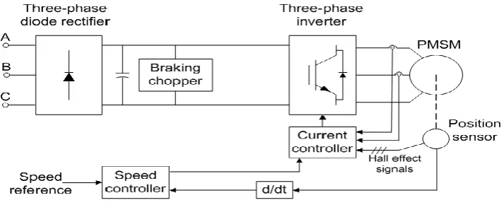
Figure 1.0: Basic scheme of permanent magnet synchronous motor
The speed controller used in the speed control system plays an important rule as it need to meet the criteria of the high performance drive. Conventional controller such as the Proportional (P) controller, Proportional Integral (PI) controller, and Proportional Integral Derivative (PID) controller can’t achieve the high performance in the speed control as there are a lot of aspect need to be take into consideration. The aspect are the changes in transient response, error integral , unknown dynamic and other factors such as noise and temperature. These changes of factor will causes the output to be shattering from the required output.
Besides, these conventional controller required accurate mathematical model to describe the dynamic of system under control and required fine tuning for the parameter variations. Lastly, the conventional controller design depend only on the exact system with accurate motor parameter and its fixed gain controller are sensitive to system disturbance.
3
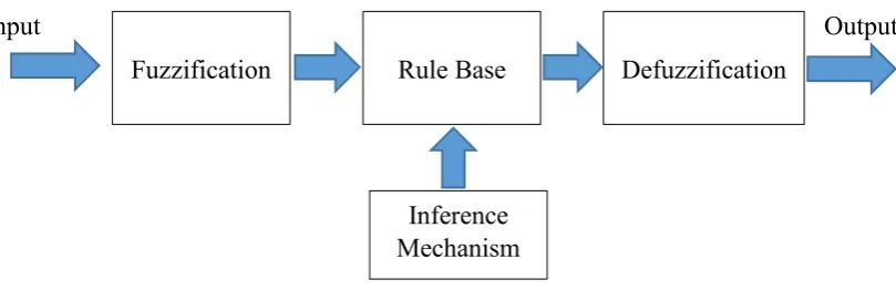
[image:22.595.104.509.95.226.2]Input Output
Figure 1.1: Basic structure of fuzzy logic controller (FLC)
Other than that, FLC have high robust ability, low cost and less complex compared with other conventional controller. The biggest difference of this controller with conventional controller is that it execute a set of control rule by following a rule base. The rule base is the IF X AND Y, THEN Z rules. Membership function also play an important roles in FLC, it need to be chosen such that it cover the whole universe of discourse. Other than that, the membership function should also overlapping with each other so to avoid any kind of discontinuity with respect to the minor changes in the inputs.
Besides, several technique such as the adaptive control, neural network control, robust control and variable structure control are introduced to overcome the nonlinearity problem and improve the dynamic response of the sinusoidal permanent magnet synchronous motor drive (PMSM) with fuzzy logic control system.
Fuzzy logic controller (FLC) solves the problem of nonlinearities and parameter variations of sinusoidal permanent magnet synchronous motor (PMSM) drive. Addition, it can achieves high dynamic performance and accurate speed control with good steady-state characteristics. The control performance can be seen in the MATLAB SIMULINK simulation with various operating with it.
Fuzzification
Inference Mechanism
4 1.2 Problem Statement
Over the decade, the usage of fuzzy logic controller have been increase in the power electronic and automotive field. This is mainly because of the easy tuning features of the fuzzy logic and the simple structure of the fuzzy logic controller which ease the implementation of the controller to the machine or system. Fuzzy logic controller is easy to implement compared to other current controller such as the Proportional Integral (PI) Controller and Proportional Integral Derivative (PID) Controller. The fixed controlled parameter of fuzzy logic controller will degrade the speed performance for different speed command. Therefore, the fixed controlled parameter need to be keep constant so that the speed performance behaviour will be constant. However, the re-tuning and designing of membership function in FLC for difference speed command is one of the problem facing in this project since there is a lot of way to design the membership function [1]. It is hard to decide which range and shape of the membership function should use for this project. Besides, it is also difficult in changing and tuning the fuzzy logic controller (FLC) in order to obtain good speed response since FLC have variation of rule [2]. The designing and tuning of the fuzzy logic controller are all by trial and error method, which mean that the process are time consuming and depend on the knowledge and experience of the user to design and utilize the fuzzy logic controller.
As a summary, the problem statement are:
I. The fixed controlled parameter which will degrade the speed performance for
different speed command.
II. The re-tuning and designing of membership function in fuzzy logic controller (FLC)
for difference speed command.
III.The difficulty in changing and tuning the fuzzy logic controller (FLC) in order to
5 1.3 Objective
The objective of this project are:
I. To design and develop a fuzzy logic controller using Matlab Simulink.
II. To investigate and analyze the speed response behavior of the drive which vary with
the constant parameter of fuzzy logic.
III. To study the correlation between rule base and membership function in speed
response behavior.
IV. To implement the fuzzy logic speed controller to the PMSM drive.
1.4 Scope
The project mainly focuses on:
i.The mathematical model of vector control of permanent magnet synchronous motor
(PMSM) drive.
ii.The control of fixed controller parameter of a sinusoidal permanent magnet
synchronous motor (PMSM) drive by using fuzzy logic controller.
iii.The modelling and simulation of Fuzzy Logic Controller (FLC) for permanent magnet synchronous motor (PMSM) drive using Matlab or Simulink.
iv.The experimental evaluation on the performances of Fuzzy Logic Controller (FLC)