Machine learning based impedance estimation in power
system
Kamyab Givaki
1*, Saleh Seyedzadeh
2, Kamyar Givaki
31 School of Engineering and Built environment, Edinburgh Napier University, Edinburgh, UK 2 Faculty of Engineering, University of Strathclyde, Glasgow, UK
3 School of Electrical and Computer Engineering, University of Tehran, Tehran, Iran
Keywords: IMPEDANCE ESTIMATION, MACHINE LEARNING, POWER SYSTEM STABILITY,
RANDOM FOREST, SUPERVISED LEARNING,
Abstract
A passive machine learning based technique to estimate the impedance of the power grid at the point of common coupling of a converter interfaced distributed generation source is proposed. The proposed method is based on supervised learning and provides a fast and accurate estimation of the grid impedance without adversely impacting the power quality of the system. This method does not need an injection of additional signals to the grid and provides an accurate estimation of the grid impedance. Multi-objective NSGA-II algorithm is used for optimisation and tuning the random forest model for accurate estimation of both R and X The resistive and inductive reactance of grid is estimated using Random Forest model due to its capability in the prediction of multiple output values simultaneously.
1
Introduction
The increasing penetration of power electronic converter interfaced distributed energy sources into the power grid, introduced new challenges to the monitoring, protection and control of the system[1]. The high amount of converter interfaced sources impacts the stability of the system, especially in a weak grid with high inductive impedance [2-6]. The knowledge of the grid impedance at the connection point of the converter to the grid (PCC) is essential for improving the control strategy and overall grid stability by either changing the control action or re-tuning the controller [7]. In micro-grids, a variation of impedance is an indication for islanding or grid connection mode operations [8]. The islanding mode can occur intentionally or forced by grid conditions. In either case, the impedance value is the indicative factor to operate the micro-grid in the islanding mode. Furthermore, the knowledge of grid impedance will be useful to improve the power quality, detection of the fault location, ground faults and grim unbalanced operation [1, 8, 9]. Various methods are proposed to estimate impedance of power network, though all of the methods can be classified into
passive and active methods [1, 2, 7, 9-15] or combination of
these two [16]. The passive methods are known to be ‘non-invasive’ and active methods are ‘‘non-invasive’.
Generally, the active methods are invasive as a disturbance signal is injected to the grid. Then the signal processing techniques are used to estimate the impedance of the grid. However, passive methods do not need any disturbance injection, and the available information of the non-characteristic current and voltage at the PCC is used to estimate the grid impedance [1, 13-17]. Hence, the performance of the power system is not degraded using passive methods.
In passive methods, either local signals or neighbouring bus and wide-area measurements can be used to estimate the impedance. However, the local signals lead to more accurate estimation as the wide-area measurement based methods are sensitive to frequency variations [16]. Local measurement based methods estimate the impedance by analysing and filtering the signals and information that are present, e.g. background voltage and current distortion [8].
Different implementations of the passive methods are presented in the literature, e.g. extended Kalman filters [2], excitation of LCL filters[12], recursive least square [10], etc. In all the passive methods as the distortion in voltage and current signals are very weak and is not repeating continuously. Therefore, the signal noise ratio (SNR) is low, which leads to an inaccurate estimate of the impedance. Active methods estimate the grid impedance more accurately.The disturbance in the active methods can be injected to the grid by using either hardware or software methods [14]. In hardware methods, the disturbance is injected to the grid by external hardware connected to the PCC. However, the software-based methods do not use an external device, and the disturbance is injected to the grid by utilising the grid-connected converter controller [14].
2 PCC as a voltage distortion or a current spike over a wide range of the frequencies [15]. Then, signal processing methods are used to estimate the parameters in the power system. These methods generate a lot of unnecessary information about the power system parameters, that might lead to over-loading of the real-time controller [15]. In steady state methods, the impedance is estimated by analysing the response of the system to injection of a periodic inter-harmonic signal. Number of implementation for active methods are presented in the relevant literature, e.g. variation of active and reactive power [9, 11, 18], discrete Fourier transform (DFT) based methods [1, 19], continuous wavelet transform based [17], discrete wavelet packet transform based[15], and particle swarm optimisation based [14].
In recent years, machine learning (ML) models have received great attention in many fields due to their ability in modelling complex systems using historical data. The use of data-driven models have been successfully demonstrated in applications demanding for real-time estimation of the targets values. These applications include building energy management systems [20], human and robot integration [21], monitoring an electric power grid [22], etc. ML models discover relationships between input variables and outputs of interest from the system being studied, learn from measured or simulated data that represents the physical problem.
Both the passive and active impedance estimation methods have shortcomings for power system applications. The passive methods can become inaccurate, and the active methods impact power quality. In this paper, the application of machines learning algorithms for impedance estimation is investigated to avoid the shortcomings of the other estimation methods.
Following this introduction, the methodology used for the proposed impedance estimation method is thoroughly presented. in section 3, the learning method results are shown and discussed. Finally, section 4 draws the conclusion of this paper.
2. Methodology
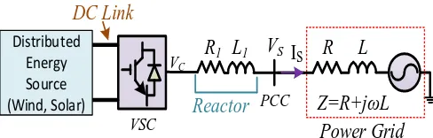
In modern distributed renewable energy resources (DG), the voltage source converters (VSC) are used for grid integration. Fig. 1 shows the schematic block diagram of the DG system used in this paper for developing and verification of the machine algorithm. This DG system comprises a converter interfaced distributed energy source, converter reactor and the grid.
As the DC link decouples the dynamics of the distributed energy source side’s dynamics from the grid side converter [3], the grid side converter of the distributed energy source is only presented. Furthermore, for simplicity, it is assumed that the rated values of the converter terminal voltage and grid at the PCC are similar. Therefore, the transformer is ignored.
A model of the system shown in Fig. 1 is developed in Matlab/Simulink. This model is used to generate the required data for the machine learning algorithms. In the development of the model per unit (p.u.) values are used.
The VSC is controlled by a vector current control scheme in which the current is controlled by decoupling the d-axis, and q-axis currents and outer control loops provide the references for the current control.
In Fig.1, R1 and L1 are the converter’s reactor resistance and inductance, respectively, and the power grid is modelled by a voltage source behind an impedance (Z). The resistive and inductive components of the impedance are then represented by R and L (X=jωL), respectively. Parameters for the test system and the current control loop are presented in Table 1.
V
SR
L
Reactor
L
1R
1I
SDistributed Energy Source
(Wind, Solar)
Z=R+jωL
Power Grid
DC Link
PCC VSC
[image:2.595.306.550.270.348.2]VC
Fig. 1. Schematic block diagram of the test system
ML models operate as a black box, so further information about the system is not required. The general scheme of supervised learning for modelling building energy is presented in [23], and a similar learning model is used in this paper to estimate the grid impedance as illustrated in Fig.2. As seen, the first step is to select a set of features for representing the building energy system. Although data-driven methods build models with fewer variables than engineering techniques, it is crucial to generate a logical input set for ML models.
[image:2.595.334.527.600.709.2]The Simulink model of the system shown in Fig. 1 was run for various combination of R and L with different active and reactive power values injected to the grid. The parameters shown in Table 1 were kept constant for all the simulations. Then, for each simulation run, the Dc link current (Idc), stationary reference frame (SRF), d-axis and q-axis, values of Table 1. Test system and VSC current control loop parameters
Parameter Value
R1 0.01 p.u.
L1 0.15 p.u
DC link voltage 800 V
Converter terminal voltage 400 V
DG rated power 1 MW
Calculation Actual Measurement
Feature extraction
Trained model
Selection of records for training, And testing processes
Test dataset Training dataset
Define training algorithm and parameters
Training and optimisation Validate
model
New system
data
Input
translation Predict
Estimated Impedance variables
Learning (training)
Prediction System
[image:3.595.46.292.71.315.2]dataset
Fig. 2. General schematic diagram of supervised learning PCC voltages (VS_d and Vs_q) and currents (IS_d and Is_q), active power (P) and frequency (Frequency) were monitored and captured. Using simulation, almost 20,000 unique records are obtained to be used in supervised learning.
[image:3.595.330.494.75.208.2]Fig.3 illustrates the distribution of all features as histogram graphs. The correlation between each pair of input and target variables is demonstrated using a heat-map matrix in Fig. 4.
Fig. 4 Impedance data features correlation map.
In this study, a Random Forest (RF) model is chosen due to its capability in the prediction of multiple output values simultaneously. RF is an ensemble of randomised decision trees which are non-parametric ML algorithms repeatedly divide the given records into smaller and smaller subsets until only one record remains in the subset. The inner and final sets are known as nodes and leaf nodes.
[image:3.595.92.502.499.759.2]RF requires several numbers of hyper-parameters to be set. Therefore, these parameters are tuned for the simulated data to achieve the highest possible accuracy. The model optimisation is performed using an evolutionary multi-objective NSGA-II algorithm to tune the RF model for accurate estimation of both R and X. In each genome (a selection of hyper-parameters), the configured model is trained and tested using 10-fold cross-validation. The model is implemented using Python programming language, and test have been carried out on a PC with Intel Core i7-6700 3.4GHz CPU, 32GB RAM.
4
3
Results
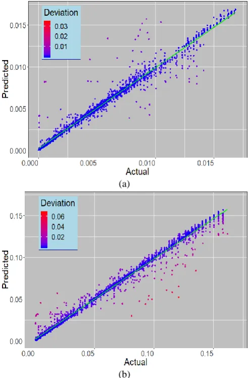
The RF model is tuned, and the best model for the simulated data and then the model is trained using 80% of records and tested with the rest as unseen data. The result of the prediction of four thousand resistance (R) and inductive reactance (X) values is demonstrated in Fig. 5 as plot of estimated versus actual values.
(a)
(b)
Fig. 5 Predicted vs actual values for a) resistance and b) inductive reactance.
Root mean square error (RMSE) and R2 are 0.0015 and 0.99 for resistance and 0.0054 and 0.98 for inductive reactance. The unit of RMSE is the same as the targets. Considering these measures, the trained model achieves high accuracy for both R and X.
Fig. 6 illustrates the histogram of the error for the test set. As it can be observed, the majority of errors are accumulated around zero.
The mean time spent for prediction of one record is calculated as 0.3ms which makes it an ideal model to be used for real-time impedance estimation .
(a)
(b)
Fig. 6 Histogram of error for a) resistance and b) inductive reactance.
4
Conclusion
[image:4.595.300.552.70.517.2] [image:4.595.46.293.180.554.2].
5 References
[1] S. d. C. Paiva, D. K. Alves, F. B. Costa, R. L. d. A. Ribeiro, and T. O. A. Rocha, "Real-Time Impedance Estimation in Grid-Connected Photovoltaic System Using the Discrete Fourier Transform," in 2018 Workshop on Communication Networks and Power Systems (WCNPS), Brasília, Brazil, Nov 2018, pp. 1-5. [2] N. Hoffmann and F. W. Fuchs, "Minimal Invasive Equivalent Grid Impedance Estimation in Inductive– Resistive Power Networks Using Extended Kalman Filter," IEEE Transactions on Power Electronics, 14, (2), pp. 631-641, 2014.
[3] K. Givaki and L. Xu, "Stability analysis of large wind farms connected to weak AC networks incorporating PLL dynamics," in International Conference on Renewable Power Generation, Beijing, China, Oct 2015, pp. 1-6.
[4] K. Givaki, D. Chen, and L. Xu, "Current Error Based Compensations for VSC Current Control in Weak Grids for Wind Farm Applications," IEEE Transactions on Sustainable Energy, 10, (1), pp. 26-35, 2019.
[5] K. Givaki, D. Chen, L. Xu, and Y. Xu, "An Alternative Current-Error Based Control for VSC Integration to Weak Grid," in 2018 IEEE Power & Energy Society General Meeting (PESGM), Portland, USA, Aug 2018, pp. 1-5.
[6] L. Zhou and Z. Mi, "Modeling and stability of large-scale PV plants due to grid impedance," in IECON 2013 - 39th Annual Conference of the IEEE Industrial Electronics Society, Vienna, Austria, Nov 2013, pp. 1025-1030.
[7] M. Sumner, A. Abusorrah, D. Thomas, and P. Zanchetta, "Improved Power Quality Control and Intelligent Protection for Grid Connected Power Electronic Converters, using Real Time Parameter Estimation," in Conference Record of the 2006 IEEE Industry Applications Conference Forty-First IAS Annual Meeting, Tampa, USA, Oct 2006, pp. 1709-1715.
[8] A. V. Timbus, R. Teodorescu, and P. Rodriguez, "Grid Impedance Identification Based on Active Power Variations and Grid Voltage Control," in 2007 IEEE Industry Applications Annual Meeting, 2007, pp. 949-954.
[9] A. V. Timbus, P. Rodriguez, R. Teodorescu, and M. Ciobotaru, "Line Impedance Estimation Using Active and Reactive Power Variations," in 2007 IEEE Power Electronics Specialists Conference, New Orleans, USA, Sep 2007, pp. 1273-1279.
[10] S. Cobreces, E. J. Bueno, D. Pizarro, F. J. Rodriguez, and F. Huerta, "Grid Impedance Monitoring System for Distributed Power Generation Electronic Interfaces,"
IEEE Transactions on Instrumentation and Measurement, 58, (9), 3112-3121, 2009.
[11] M. Ciobotaru, R. Teodorescu, P. Rodriguez, A. Timbus, and F. Blaabjerg, "Online grid impedance estimation for single-phase grid-connected systems using PQ variations," in 2007 IEEE Power Electronics Specialists Conference, Orlando, USA, June 2007, pp. 2306-2312.
[12] M. Liserre, F. Blaabjerg, and R. Teodorescu, "Grid Impedance Estimation via Excitation of LCL -Filter Resonance," IEEE Transactions on Industry Applications, 43, (5), pp. 1401-1407, 2007.
[13] A. Ghanem, M. Rashed, M. Sumner, M. A. El-sayes, and I. I. I. Mansy, "Grid impedance estimation for islanding detection and adaptive control of converters," in 8th IET International Conference on Power Electronics, Machines and Drives (PEMD 2016), Glasgow, UK, April 2016, pp. 1-6.
[14] K. Lin, F. Xiao, and G. Jie, "Grid impedance estimation based on particle swarm optimization," in 2017 IEEE 2nd Advanced Information Technology, Electronic and Automation Control Conference (IAEAC), Chongqing, China, March 2017, pp. 573-576.
[15] D. K. Alves, R. Ribeiro, F. B. Costa, and T. O. A. Rocha, "Real-Time Wavelet-Based Grid Impedance Estimation Method," IEEE Transactions on Industrial Electronics, Early Access, 2018.
[16] M. Kosmecki and R. Rink, "Hybrid Method for Grid Impedance Estimation Based on Local Measurements," in 2018 IEEE 59th International Scientific Conference on Power and Electrical Engineering of Riga Technical University (RTUCON), Riga, Latvia, November 2018, pp. 1-4.
[17] P. Zanchetta, A. Abusorrah, D. W. P. Thomas, M. Sumner, P. Zanchetta, A. Abusorrah, et al., "Power System Impedance Estimation for Improved Active Filter Control, using Continuous Wavelet Transforms," in 2005/2006 IEEE/PES Transmission and Distribution Conference and Exhibition, Dallas, USA, May 2006, pp. 653-658.
[18] A. Tarkiainen, R. Pollanen, M. Niemela, and J. Pyrhonen, "Identification of grid impedance for purposes of voltage feedback active filtering," IEEE Power Electronics Letters, 2, (1), 6-10, 2004.
6 inverters," IEEE Transactions on Industrial Electronics, 52, (4), pp. 1136-1144, 2005.
[20] S. Seyedzadeh, F. Pour Rahimian, P. Rastogi, and I. Glesk, "Tuning machine learning models for prediction of building energy loads," Sustainable Cities and Society, 47, p. 101484, 2019/05/01/ 2019.
[21] P. M. Pilarski, M. R. Dawson, T. Degris, J. P. Carey, and R. S. Sutton, "Dynamic switching and real-time machine learning for improved human control of assistive biomedical robots," in 2012 4th IEEE RAS & EMBS International Conference on Biomedical Robotics and Biomechatronics (BioRob), Rome, Italy, June 2012, pp. 296-302.
[22] V. S. Budhraja, J. D. Dyer. C. A. M. Morales, "Real-time performance monitoring and management system," 2007.
[23] S. Seyedzadeh, F. P. Rahimian, I. Glesk, and M. Roper, "Machine learning for estimation of building energy consumption and performance: a review,"