R E S E A R C H
Open Access
Statistical MIMO beam codebook design
for mmWave transmissions
Majid Nasiri Khormuji
*and Renaud-Alexandre Pitaval
Abstract
We propose a novel method for constructing beam codebooks, i.e., a set of beamforming weights, to be used for beam sweeping and data transmission in mmWave massive MIMO channels. The proposed beam codebooks are designed according to the statistical distribution of the channel’s angles of departure in order to efficiently sectorize the angular space covered by the beams. In particular, the cumulative distribution function of these angles is used to sectorize the angular beam space in order to design the beams. We first present a general closed-form construction of beam codebooks for an arbitrary distribution and then tailor the results to the Laplace distribution. We consider both narrow and broad beams. The resulting beams are a priori better adapted to the channel statistics and thus enhance the spectral efficiency of the transmission as compared to the state-of-the-art beam designs. Finally, we investigate the performance of the design and also present some analytical bounds quantifying the inherent loss of a directional beamforming compared to the optimal beamforming with perfect channel state information at the transmitter.
Keywords: mmWave, Massive MIMO, Beam sweeping, Beamforming, Statistical codebooks
1 Introduction
Next generation wireless communication is expected to support various vertical industries in which there is need for wireless communication links with shorter latency, higher reliability as well as the more traditional metric of higher transmission rates. In light of this view, massive MIMO in conjunction with signaling using electromag-netic waves with shorter wavelength such as millime-ter waves (mmWaves), has received notable attentions and been subject of intensive academic and industrial research [1–7].
Beam sweeping [8–13] is an appealing approach for mmWave massive MIMO communications, by which the transmitter radiates multiple beams in different directions to find the best transmission direction through feedback from the receiver side for beamforming of the modulated data sequences. In massive MIMO systems, when the number of antennas increases, the transmitter becomes capable of generating narrow beams that enable so-called pencil beamforming. The pencil beamforming provides links with a boosted received signal-to-noise ratio (SNR) since the transmitted energy is concentrated in a desirable
*Correspondence:[email protected]
Huawei Technologies Sweden AB, 164 94 Kista, Sweden
direction. In addition, the pencil beamforming creates less interference on unintended neighboring nodes as the transmitted energy is mostly directed toward the indented receiver.
The mmWave channels are highly directional and often have few physical paths which can be parameterized by their angles-of-departure (AoDs). Thus, the beam code-book design for mmWave channels can be simplified to a low-dimensional quantization problem on the AoD domain [8–10,13]. A common solution for beam sweep-ing is to construct beams thatuniformlyspan the angular range of the channel [8–12]. Additionally, it is desirable to optimize the width of the main lobe such that the set of beams covers the entire angular range to avoid outage events [9–11].
Beam sweeping is included in the ongoing 3GPP Next Radio (NR) specification (a.k.a 5G), in which a beam sweeping session starts with a time slot wherein the refer-ence symbols (RSs) for new beam identification is trans-mitted. Using the received RSs, the user equipment (UE) prepares a feedback signal to be transmitted to the Base Station (BS). The BS employs this feedback to select a suit-able beam to beamform the modulated data symbols. In the 3GPP specifications, two types of downlink RSs can be
used for a new beam identification: Channel State Infor-mation RS (CSI-RS) and Synchronization Signals (SS). The period of such RSs defines the time span of beam sweeping session. The periodicity of SS could be selected from the set {5, 10, 20, 40, 80, 160} ms, and the periodic-ity of CSI-RS could be as short as 1 ms. The selection can be made based on the requirements of a particular deployment scenario1.
For an initial beam sweeping session without a pri-ori knowledge, a uniform distribution of AoDs may be assumed and a uniform beam codebook shall be used. Then, the receiver reports the index of the beam(s) with the highest received power to the transmitter. However, after operation of the network during a time interval, accumulated feedback in the training procedure creates a history of selected transmission angles which can be used to acquire AoD statistics to construct non-uniform codebooks. Namely, due to the high directionality of the mmWave channel, a good transmission direction for a subsequent beam sweeping session is likely to be in the angular vicinity of the last reported beam where its devi-ation varies by the mobility of the user. For example, at the ith session, the main AoD φ could be modeled by a cumulative distribution function (cdf )
F(φ)=Fmi−1,σi2
, (1)
whose meanmi−1corresponds to the center of the main
lobe of the last reported beam, and variance can be esti-mated, e.g., from the angular difference between subse-quent selected directions as σi2 = Ek<i
(mk−mk−1)2
which can be assumed to be approximately constant as it mostly depends on the UE’s speed and geometrical vari-ations of the environment. The shape of the distribution can be a priori determined, e.g., the Laplace distribu-tion is a common choice ofF, which has been used in [11,12,14]. The prior knowledge of AoD distribution may particularly be useful in indoor deployment where move-ments and variations of the environment are quasi-static. Finally, from the collected statistics, it is desirable to pri-marily sweep with a high beamforming gain in previous beam directions while still maintaining lower-gain periph-eral beams for the purpose of enhanced link support.
To the best of our knowledge, anon-uniformbeam code-book design has not been considered in earlier work. In this paper, we assume that such AoD statistics is known and focus on the beam codebook design for a subsequent beam sweeping session with a known cdf. We exploit the
statistical distribution of channel’s directional angles to construct closed-formnon-uniformbeam codebooks for an arbitrary cdf to enhance the spectral efficiency of the transmission. Particularly, we use the mapping of inverse cdf to generate biased uniform samples for angle quantiza-tion to shape non-uniform beams. Numerical evaluaquantiza-tions
show that the designed non-uniform beams can bring SNR gains of several dBs over the uniform beams.
The remainder of the paper is organized as follows: Section 2 states the system model that we consider in this paper and outlines assumptions used in the channel modeling. Section3introduces the concept of statistical beam design for an arbitrary cdf of AoD and then tai-lors the design to the Laplace distribution. Section4then illustrates radiation patterns of the new beam codebooks and provides some numerical evaluations and analyti-cal bounds on the ergodic achievable transmission rates. Section5finally concludes the paper and provides some directions for future work.
2 System model 2.1 Transmission
We consider a single stream data transmission from a base station withNtantennas over a wireless channelh∈ CNt×1to a single-antenna user2.
An information bearing symbolx ∈ Cis transmitted from the antenna array via a beamforming vector w ∈
CNt×1, such that the received symbol at the user is
y=h†wx+z (2)
where E|x|2 = P,w2 = 1,z ∼ CN(0,N0) is a
com-plex zero-mean additive white Gaussian noise (AWGN) with variance N0 and(·)† denotes Hermitian transpose.
We assume a directional geometric channel model where the channelhis constituted of fewNppaths such that
h=Nt
Np
l=1αla(φl) (3)
where αl ∼ CN(0,σl2) is the complex gain of the lth path, modeled as an independent and identically dis-tributed (i.i.d) complex Gaussian variable, a(φ)denotes the transmitter normalized antenna array response at the corresponding AoD, and φl is the AoD of thelth path. The sum of the average power of the paths is normalized such that σl2 = 1. The AoDs are assumed to be ran-domly distributed with standard deviationσφ according to cdfFdefined on the angular support [φmin, φmax]. The
support can represent a physical property of the commu-nication scenario such as cellular sectorization. Outside of the angular range [φmin, φmax], the channel response is
considered too weak to be detectable by the receiver. The beamforming vectorwis selected in a training pro-cedure using a set of M beams from a beam codebook
a corresponding beam index via a feedback link to the transmitter. Finally, the transmitter uses the selected beam for data transmission.
In this work, we propose a new approach to design
W using the distributionof AoDs. While the proposed codebooks can be extended to any type of arrays, for the simplicity of exposure, we will primarily focus on a uniform linear array (ULA) withNt-element with inter-element spacingd, whose array response at angleφfor a carrier with wavelengthλis
a(φ)=√1 Nt 1, e
−j2πλdsinφ, . . ., e−j2πλd(Nt−1)sinφT.
(4)
2.2 Codebook design and statistical CSI
In conventional Rayleigh-faded MIMO channels, MIMO codebooks are designed to provide a discretization of a high-dimensional vector spaces. Due to rich scatter-ing, a rather uniform quantization is first targeted, while spatial correlation property are independently fed back for adaptive precoding according to long-term statistics (see, e.g., [15–17]).
On the contrary, the mmWave channel is highly direc-tional and constituted mostly of few physical paths. Each path’s direction is parameterizable by AoDs, i.e., one or two degrees of freedom according to the array dimen-sionality. Thus, for mmWave channel, beam codebook design can be simplified to a low-dimensional quantiza-tion problem in the AoD domain [8–10]. Furthermore, the directionality of the channel implies a high correlation dominated by large-scale parameters.
The directionality of the channel makes the channel much more correlated in time as it is mostly dominated by large-scale effects to the limit of blockage. For example, the natural approach in mmWave tracking is to search in the neighborhood of the previously selected beam, while large side-lobe may still be desirable for avoiding outage.
In order to exploit this correlation, we assume that the transmitter has access to statistical CSI and is able to com-pute an estimate of the distribution of the AoDs. The sta-tistical properties can be obtained a priori or by an explicit feedback link. Note that for a number of distributions, determining the variance and mean of a random variables is enough to fully describe the statistics. Alternatively, sta-tistical CSI can be obtained by memory operation of the network during a time interval. The optimal base beam codebook in the absence of any prior angular information is uniform in the angular domain to cover all angles in order to minimize the outage performance.
Accumulation of feedback for training procedure in a time interval creates a history of selected angular trans-missions which can be used to obtain statistical properties
of the selected angles. Then, based on this statistical properties one can update the beam codebook.
3 Statistical beam codebook design
In this section, we first briefly discuss non-uniform quan-tization and then introduce a method to construct sta-tistical non-uniform beam codebooks for an arbitrary cdf of AoD and finally tailor the results to the Laplace distribution.
3.1 Non-uniform scalar quantization
Given a continuous random variable with cdf F, a quantization Q is a mapping from to a finite set of quantization level{φ1,. . .,φM} with decision thresholds
{t0,. . .,tM}such thatQ(φ)=φkifφ∈[tk−1tk)3. An
opti-mal mean-squared error (MSE) quantizer [18] satisfies the following two conditions:
i) The decision thresholds are halfway of neighboring quantization levels,
tk= φk+1−φk
2 , (5)
ii) The quantization levels are centroids of the
quantization intervals, i.e., the levels are given by the conditional means
φk = 1
F(tk)−F(tk−1) tk
tk−1
φdF(φ). (6) These two conditions are coupled and the optimal quan-tizer can be found by a recursive algorithm.
Alternatively, it is also known that any non-uniform scalar quantizer can be constructed using a compander [19] such that the random variableis uniformly quan-tized after a monotonic smooth transformationF. Namely, for a realizationφ of , a non-uniform quantization is constructed as
Q(φ)=F−1(QU(F(φ))) (7)
where QU is a uniform quantizer on the image of F. A good practical choice ofFis the cdf ofsince the random variableF()is uniformly distributed.
For the problem of beam codebook design, the com-panding method can be used to construct beams that possess enhanced statistical properties for the beam iden-tification. Particularly, we employ the transformation
F = F (and thus drop the subscript) to first construct the decision thresholds (5) and then train several beams corresponding to the quantization levels (6).
3.2 Non-uniform beam codebook design
Ii = [di−1, di], fori = 1,. . .,Mwithdi = Mi . Accord-ingly, we construct the sector of theith beam as
Si=
∪iSiis thus done in a way that the probability that an angle belongs to each sub-rangeSiis the same.
We next describe narrow and broad beam generation methods for each constructed angular sector.
3.2.1 Narrow beams
In the first method, each beam is simply determined by a single angle which results in a narrow beam. We select this angle as the mean direction of the beam sector given in (8). That is, the expected angle is calculated as in (6)
In order to simplify the derivation, we approximate the mean (9) by the median of the sectorized distribution
φi≈F−1di−12+di=F−122i−M1, (10)
for i = 1,. . .,M. This approximation would be exact if the distribution restricted on the sector would not be (non-parametrically) skewed. The angle (10) is then used as the main lobe direction to construct theith beam. For a ULA array withNtantennas, the narrow beam codebook
Wn= {wn,i}Mi=1is constructed according to
These beams are constructed with fixed width that depends only on the number of transmit antennas and is independent of the size of the codebook. The advantages of this method is that it provides the maximum beam-forming gain when the beam is aligned with the channel, and it can be implemented with only one phase-shift per antenna. However, such design may lead to a too narrow beam for the size of the sector it should cover, specially for arrays with a high number of antennas. Thus, the main drawback is the narrow beams are more prone to detec-tion outage. We therefore generalize the design method to construct non-uniform broad beams in the following.
3.2.2 Broad beams
A method to construct broad beams has been described in [9–11]. This method follows from (i) constructing a larger codebook with a high angular resolution; (ii) assign-ing an angular sector for each desired broad beams; and (iii) combining high-resolution beams in each sector to form a broad beam. In the step (iii), an arithmetic average (i.e., equal gain combining) of the high-resolution beams is used in [9]. In [10, 11] more sophisticated combin-ing methods are developed to provide constant main-lobe directivity gain.
We adapt in below this broad beam design to our non-uniform quantization approach. Each beam sector Si is initially quantized intoNqquantization points whereNqis a design parameter. We present two alternative methods of sector quantization.
Sector quantization 1 The first method consists of uniformly quantizing the sectorSias
¯
whereNqis a design parameter that indicates the number of quantization points. This method aims to target a more uniform coverage inside each sectorSi, to enable lower angular outage.
Sector quantization 2 The second method uniformly quantizes the intervalIi = [di−1, di] , i.e., the portion of cdf corresponding to sectorSias
¯
Then, the quantized angles in the sector Si are con-structed by inverse mapping of the cdf as
¯ power to angles with higher likelihood inside the sector
Si. This hence improves the average beamforming gain.
Beam generation Once the quantized sectorS¯ihas been determined, a beam for the sectorSi is constructed by a linear superposition of narrow beams at the quantized points. This is given as
wb,i= tor of the narrow beam at angleθ to generate broad beam
i, and βi is a normalization constant to ensure the total power constraint at the transmitter. The weighting factor can be selected to be either an arithmetic averagewi,θ =
1
Nq for all iandθ [9], or optimized as in [10,11,13] to satisfy other criteria.
3.3 Proposed beams for Laplace distribution
Here we exemplify the proposed general design to the Laplace distribution of the AoDs [11, 12, 14] to obtain closed-form non-uniform beams. The Laplace pdf [20] is given by
andσφ is the standard deviation. The constantkis a nor-malization factor to ensureφmax
φmin f(φ)dφ = 1, which is
The corresponding cdf [20] can be found to be
F(φ)= 12kc+12k·sign(φ−mφ) 1−exp− sign(·)returns the sign of its argument. The inverse cdf is then
For the ULA, the beam codebookWfor the Laplace dis-tribution can be computed by using (21) in conjunction
with (11) and (17) to obtain narrow and broad Laplacian beams, respectfully. The final result for Laplacian broad beams using, e.g., sector quantization 2 is given at the top of this page.
4 Performance evaluations
In this section, we assess the performance of the pro-posed statistical beam codebooks by numerical evaluation and also present some analytical upper bounds on the ergodic achievable transmission rate. We assume that the transmitter is equipped with a ULA array with Nt = 64 elements with half-wavelength antenna spacing. The channel is assumed to haveNppaths where each of them has equal average power, i.e.,σl2=1/Np. We further con-sider that each path has an AoD that follows a Laplace distribution4m
φ = 0 and standard deviationσφ =7◦on
the angular support [−30◦, 30◦], as in [11].
4.1 Beam radiation patterns
Figure1illustrates the radiation patterns of uniform code-books (as those in [9–11]) and of the proposed codebooks with sectorization (12) for codebook sizesM = 8, 16, and 32. For all cases, the angular support is assumed to be [− 30◦, 30◦]. The Laplacian beams are constructed by using the assumptions that mφ = 0 and standard deviationσφ = 7◦. The broad beams are constructed by arithmetic average over a fixed number of quantization points per sector, whereNq=50.
We observe that the new design has the advantage to treat the radiation anglesnon-uniformlyby allocating its radiation power on the angles that are more probable based on the assumed cdf. As a result, likely angular direc-tions are allocated with more power. For example, the maximum power of strongest beams of the non-uniform codebooks reach 8 dB gain fromM=8 beams, while this is only achieved with M = 32 with the uniform code-book. In general, as the number of beams M increases the beamforming gain of the associated beams increases. The main reason behind this is the fact that as the num-ber of beams increases, the width of the beams decrease and hence the radiated energy of a particular beam is distributed on a narrower angular range which in turn increases the corresponding beamforming gain. However, the Laplacian design does not uniformly decreases the width of all beams, as a result, increased beamforming gain asMincreases is obtained mainly for the peripheral beams to the mean value. This is an important advan-tage of the design enabling higher transmission rates as discussed in the sequel.
4.2 Achievable transmission rate
-30
Fig. 1Radiation patterns of the conventional uniform beam codebooksa–cand Laplacian beam codebooksd–fforNt=64 on the angular support [−30◦, 30◦]. For the Laplacian beams, it is assumed thatmφ=0 and standard deviationσφ=7◦
the length of each codeword, one can conclude that the transmission rate
R=Elog21+snr· |h†w∗|2
(22)
is achievable where w∗ is the selected beam from the beam codebook in the beam sweeping procedure and snr := P/N0wherePis the average transmit power and N0 is the variance of AWGN at the receiver. That is as
the length of each codewordnincreases the transmission with above rate with negligible probability of error at the receiver becomes feasible. The set of precoding vectors,
w, is the design parameter to enlarge the achievable transmission rate. With the feedback mechanism in place, the beam with the highest receiver power is selected for the data transmission. We highlight that we didn’t include the overhead into rate calculation in22to study
the effect the beamforming gain by increasing the size of the beam codebook.
4.3 Upper bound on achievable transmission rate As the number of antennas increases the number of beams in the beam codebook can be increased as well. This hence enables to perform an enhanced beam training at the expense of higher overhead in the beam sweeping as well as the feedback transmission from the UE. That is, for large number of antennas, narrow beams can reach a far better angular precision so that with a very large beam codebook size only the strongest path of the channel (3) is captured, i.e.,|h†w∗|2 Nt
|αi|2Np
i=1forNt,M 1.
The rate in (22) is furthermore upper bounded by
C=Elog21+snr· h2 (24)
which is achieved using maximum ratio transmission, i.e.,
wopt=h/hby assumingperfectchannel state
informa-tion (CSI) at the transmitter.
4.4 Asymptotical loss of directional beamforming The discussed directional beam sweeping procedure, even with an infinitely large codebook, has an inherent loss compared to the perfect CSI beamforming. To quantify this loss, we respectively bound the maximum achievable rate in (23) and the perfect CSI bound in (24) by Jensen’s inequality, i.e.Elog(1+x)≤log(1+Ex). This yields
Rmax≤ ¯Rmax=log2
1+snr·Nt·Emax
|αi|2Np
i=1
(25)
C ≤ ¯C=log21+snr·Eh2. (26)
The average SNR of beam sweeping inR¯maxcan be
sim-ilarly derived as that of selection diversity combining [22]
¯
Rmax=log2
1+snr·Nt·Np−1·
Np
l=1l
−1 (27)
which follows from order statistics and the assump-tion that the paths are i.i.d Rayleigh faded with aver-age power Np−1. On the other hand, Eh2/Nt → 1 as Nt → ∞ in (26), since the array response vec-tors become asymptotically mutually orthogonal and thus
¯
C≈log2(1+snr·Nt). Accordingly, at high SNR we obtain
¯
Rmax/C¯ ≈log2
Np−1Np
l=1l
−1 (28)
which provides an estimate ofRmax/C. The loss increases
withNp, which is in agreement with the findings in [13].
4.5 Numerical examples
We next provide some numerical examples along with the discussed bounds on the achievable rates for different scenarios.
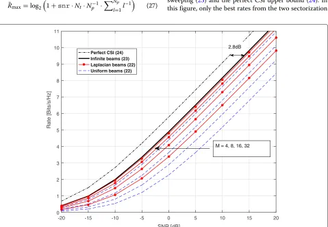
4.5.1 Case 1: Np=4
In this section, we set the number of paths toNp = 4. Figure2shows the rates (22) achievable by the proposed statistical broad beam codebooks and the conventional uniform broad beam codebooks, both with sizeM = 4, 8, 16, and 32, along with the maximum rate of beam sweeping (23) and the perfect CSI upper bound (24). In this figure, only the best rates from the two sectorization
-20 -15 -10 -5 5 10 15 20
SNR [dB] 0
1 2 3 4 5 6 7 8 9 10 11
Rate [Bits/s/Hz]
Perfect CSI (24) Infinite beams (23) Laplacian beams (22) Uniform beams (22)
2.8dB
M = 4, 8, 16, 32
0
methods in (12) and (16) are displayed. The radiation patterns of the uniform codebooks (as those in [9–11]) and the proposed codebooks with sectorization (12) for
M = 8, 16, and 32 are shown in Fig. 1. From Fig. 2, it is seen that the proposed method significantly out-performs the conventional solution. ForM = 4, 8, 16, and 32, the new method respectively amounts to SNR gains of 4.2, 4.1, 3.0, and 1.2 dB. The gain is more pro-nounced for smaller-size codebooks as the new design efficiently places the beams according to the distribu-tion of AoDs. For high-resoludistribu-tion codebooks, uniform beams are also asymptotically optimal. However, the sta-tistical beam codebook converges faster to the maximum rate (23) which is nearly achieved withM = 32 beams for this example. We also see that the new codebook with
M = 16 slightly outperforms the conventional uniform codebook withM=32 beams, which corresponds to 50% pilot overhead reduction for beam training yet maintain-ing a similar performance. The SNR gain reduces with large codebook size as for high-resolution quantization random coding is known to be asymptotically optimal. For this scenario, the analytical loss of the beam sweep-ing with respect to the perfect CSI in (28) corresponds to 4/1+12+31+14 ≈ 1.92 ≈ 2.8 dB SNR loss which
indeed well quantifies the SNR loss betweenRmaxandC
as numerically evaluated and marked in Fig.2.
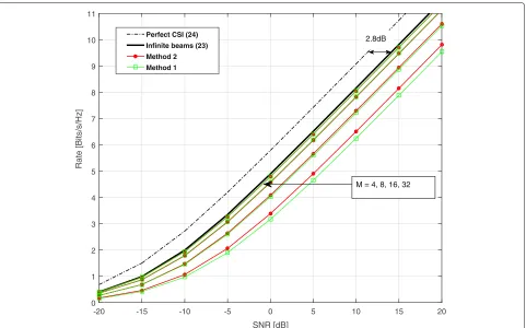
Figure3compares the two sectorization methods for the above case. We see that the method in (16) outperforms that in (12) with a SNR gain of 0.9 dB forM=4. However, the two methods perform similarly for largerM. This is because the second sectorization method is more power efficient when the number of beams is limited.
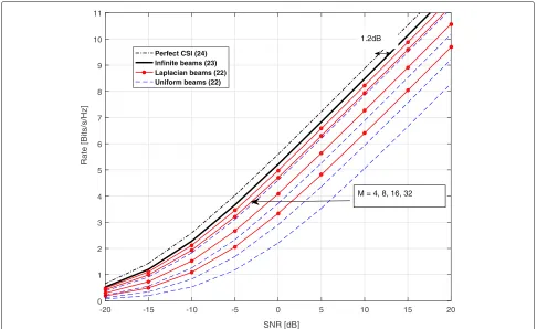
4.5.2 Case 2: Np=2
We next set the number of paths to Np = 2 and keep the same parameters and beam design as those in case 1 withNp = 4. Figure4shows the rates (22) achievable by the proposed statistical broad beam codebooks and the conventional uniform broad beam codebooks, both with size M = 4, 8, 16, and 32, along with the maximum rate of beam sweeping (23) and the perfect CSI upper bound (24). We see again that the proposed design out-performs the conventional uniform beam sweeping with the same trend in gains with increased codebook size as in Fig.2. However, since the number of paths is reduced, the gap to perfect CSI beamforming is also reduced, which is in accordance with the analytical evaluations. In the case with Np = 2, the gap of the beam sweeping with
-20 -15 -10 -5 5 10 15 20
SNR [dB] 0
1 2 3 4 5 6 7 8 9 10 11
Rate [Bits/s/Hz]
Perfect CSI (24) Infinite beams (23)
Method 2 Method 1
M = 4, 8, 16, 32 2.8dB
0
-20 -15 -10 -5 5 10 15 20
SNR [dB] 0
1 2 3 4 5 6 7 8 9 10 11
Rate [Bits/s/Hz]
Perfect CSI (24) Infinite beams (23) Laplacian beams (22) Uniform beams (22)
M = 4, 8, 16, 32 1.2dB
0
Fig. 4Spectral efficiency achieved by Laplacian beam codebooks compared to uniform beam codebooks for various numbers of codebook sizes M= {4, 8, 16, 32}andNp=2
large enough beams to the perfect CSI at high SNR is 2/1+ 12≈1.33≈1.2 dB as marked in Fig.4. The same behavior for the sectorization methods as that forNp=4 is observed for this case as well.
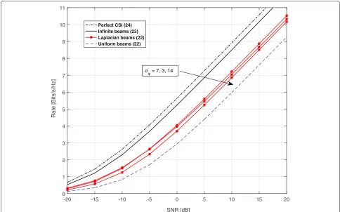
4.5.3 Case 3: Np=2with mismatch
Finally, we set the number of paths to Np = 2, but we assume that there is a mismatch between the cdf of channel’s AoDs and the assumed cdf for beam codebook construction. In particular, we assume that the standard deviation for actual angles of the radio channel isσφ=7◦ but the beams are designed by settingσφ =3◦, 7◦, and 14◦ when the size of the codebook isM= 8. Figure5depicts the rates (22) achievable by the proposed statistical broad beam codebooks with the three standard deviations and the conventional uniform broad beam codebooks, both with sizeM = 8 along with the maximum rate of beam sweeping (23) and the perfect CSI upper bound (24). We observe that exact knowledge of the channel character-istics of the angles for the design of the beam codebook amounts to the highest achievable rates, and having a mis-match between the standard deviation value used for the beam design and that of the actual channel can reduce the performance. Nevertheless, even with the considered mismatched values, there is a notable gain with respect to
the conventional uniform beam design. The highest gain at 8 bits/s/Hz is achieved whenσφ = 7, which is equal to 3.8 dB. The SNR gains of mismatched codebooks with σφ =3◦and 14◦are 3.2 and 2.7 dB, respectively.
5 Conclusions
We introduced statistical beam codebooks based on the
-20 -15 -10 -5 5 10 15 20
SNR [dB] 0
1 2 3 4 5 6 7 8 9 10 11
Rate [Bits/s/Hz]
Perfect CSI (24) Infinite beams (23) Laplacian beams (22) Uniform beams (22)
σφ = 7, 3, 14
0
Fig. 5Spectral efficiency achieved by Laplacian beam codebooks compared to uniform beam codebooks withM=8 beams. The Laplacian beams are designed for standard deviationsσφ=3◦, 7◦, and 14◦for a channel withNp=2 andσφ=7◦
are generated by quantization in the angular domain, extension to 2D array can be done by treating both the azimuthal and elevation angular domains. This is left to potential future work. Further extensions of the work include the design of broad beams by finding optimal lin-ear combining as in [10, 11, 13] and quantifying their performance. We would also like to highlight that the current beam design is based on MSE criteria which is not necessarily optimal for the rate maximization, but it nevertheless provides encouraging performance gains. The current analysis did not include the beam train-ing overhead. Therefore, the work can be also extended by including the training overhead into the rates as for example in [23].
Endnotes
1The 5G technical specification is not yet fully
com-pleted but the above timing configurations are very likely to be freezed for the first release.
2Or a multiple-antenna user with a receiver
steer-ing vector. The selected receiver steersteer-ing vector may be absorbed in the channel model which is then reflected in the feedback selection.
3Extreme values are set to match the support of, and
boundaries are split arbitrarily as they occur with zero probability.
4In practice, mean and variance fluctuate according to
user’s mobility as discussed in the introduction. Here it is set arbitrarily to constant values without loss of generality since it is assumed to be acquired at the transmitter.
Authors’ contributions
Both authors substantially contributed to the paper. Both authors read and approved the final manuscript.
Competing interests
The authors declare that they have no competing interests.
Publisher’s Note
Springer Nature remains neutral with regard to jurisdictional claims in published maps and institutional affiliations.
Received: 18 October 2017 Accepted: 30 July 2018
References
1. JG Andrews, S Buzzi, W Choi, SV Hanly, A Lozano, AC Soong, JC Zhang, What will 5G be? IEEE J. Sel. Areas Commun.32(6), 1065–1082 (2014) 2. TS Rappaport, S Sun, R Mayzus, H Zhao, Y Azar, K Wang, GN Wong,
3. F Boccardi, RW Heath, A Lozano, TL Marzetta, P Popovski, Five disruptive technology directions for 5G. IEEE Commun. Mag.52(2), 74–80 (2014) 4. C-X Wang, F Haider, X Gao, X-H You, Y Yang, D Yuan, H Aggoune, H Haas,
S Fletcher, E Hepsaydir, Cellular architecture and key technologies for 5G wireless communication networks. IEEE Commun. Mag.52(2), 122–130 (2014)
5. W Roh, J-Y Seol, J Park, B Lee, J Lee, Y Kim, J Cho, K Cheun, F Aryanfar, Millimeter-wave beamforming as an enabling technology for 5G cellular communications: Theoretical feasibility and prototype results. IEEE Commun. Mag.52(2), 106–113 (2014)
6. N Cardona, LM Correia, D Calabuig, Key enabling technologies for 5G: Millimeter-wave and massive MIMO. Int. J. Wirel. Inf. Networks.24(3), 201–203 (2017). Available:https://doi.org/10.1007/s10776-017-0366-z
7. TK Vu, C-F Liu, M Bennis, M Debbah, M Latva-aho, CS Hong, Ultra-reliable and low latency communication in mmWave-enabled massive MIMO networks. IEEE Commun. Lett.21(9), 2041–2044 (2017)
8. S Hur, T Kim, DJ Love, JV Krogmeier, TA Thomas, A Ghosh, Millimeter wave beamforming for wireless backhaul and access in small cell networks. IEEE Trans. Commun.61(10), 4391–4403 (2013)
9. J Seo, Y Sung, G Lee, D Kim, Training beam sequence design for millimeter-wave MIMO systems: A POMDP framework. IEEE Trans. Sig. Proc.64(5), 1228–1242 (2016)
10. S Noh, MD Zoltowski, DJ Love, inProc.IEEE Global Commun. Conf. Multi-resolution codebook based beamforming sequence design in millimeter-wave systems (IEEE, San Diego, 2015), pp. 1–6
11. S Noh, MD Zoltowski, DJ Love, Multi-resolution codebook and adaptive beamforming sequence design for millimeter wave beam alignment. IEEE Trans. Wirel. Commun.16(9), 5689–5701 (2017)
12. OE Ayach, S Rajagopal, S Abu-Surra, Z Pi, RW Heath, Spatially sparse precoding in millimeter wave MIMO systems. IEEE Trans. Wirel. Commun.
13(3), 1499–1513 (2014)
13. V Raghavan, J Cezanne, S Subramanian, A Sampath, O Koymen, Beamforming tradeoffs for initial UE discovery in millimeter-wave MIMO systems. IEEE J.Sel. Topics Signal Process.10(3), 543–559 (2016) 14. A Forenza, DJ Love, RW Heath, Simplified spatial correlation models for
clustered MIMO channels with different array configurations. IEEE Trans. Veh. Tech.56(4), 1924–1934 (2007)
15. T Shuang, T Koivisto, HL Maattanen, K Pietikainen, T Roman, M Enescu, in
Proc. IEEE Veh. Tech. Conf. Design and evaluation of LTE-advanced double codebook (IEEE, Yokohama, 2011), pp. 1–5
16. DJ Love, RW Heath, Limited feedback diversity techniques for correlated channels. IEEE Trans. Veh. Technol.55(2), 718–722 (2006)
17. P Xia, GB Giannakis, Design and analysis of transmit-beamforming based on limited-rate feedback. IEEE Trans. Signal Process.54(5), 1853–1863 (2006)
18. J Max, Quantizing for minimum distortion. IRE Trans. Inf Theory.6(1), 7–12 (1960)
19. RM Gray, DL Neuhoff, Quantization. IEEE Trans. Inf. Theory.44(6), 2325–2383 (1998)
20. S Kotz, T Kozubowski, K Podgorski,The Laplace distribution and generalizations: a revisit with applications to communications, economics, engineering, and finance. (Springer Science & Business Media, 2012). ISBN 978-1-4612-0173-1
21. A El Gamal, Y-H Kim,Network information theory. (Cambridge university press, 2011)
22. DG Brennan, Linear diversity combining techniques. Proc. IRE.47(6), 1075–1102 (1959)
![Fig. 1 Radiation patterns of the conventional uniform beam codebooks a–c and Laplacian beam codebooks d–f for Nt = 64 on the angularsupport [ −30◦, 30◦]](https://thumb-us.123doks.com/thumbv2/123dok_us/918405.1111201/6.595.56.543.86.453/radiation-patterns-conventional-uniform-codebooks-laplacian-codebooks-angularsupport.webp)