Abstract— This paper presents a speed control of induction
motor based on sliding-mode controller approach. The back Electromotive force is calculated from currents and voltages of stator. The magnetizing currents are obtained from the back EMF. A theorem which gives the rotor speed estimate in the continuous-time domain is formulated using the magnetizing current estimation. The stability analysis is achieved based on the Lyapunov approach. The result of Speed control of induction motor based on sliding mode controller is simulated using MATLABR2009a
Index Terms—induction motor, sliding mode controller,
rotor speed observer, Back EMF.
I. INTRODUCTION
The industrial standard for high performance motion control applications require, four quadrant operation including field weakening, minimum torque ripple, rapid speed recovery under impact load torque and fast dynamic torque and speed responses. DC motors with thyristor converter and simple controller structure have been the traditional choice for most industrial and high performance applications. But they are associated with certain problems related to commutation requirement and maintenance. Low torque to weight ratio and reduced unit capacity add some more negative points to DC machine drives. On the other hand AC motors, especially induction motors are suitable for industrial drives, because of their simple and robust structure, high torque to weight ratio, higher reliability and ability to operate in hazardous environments. However there control is a challenging task because the rotor quantities are not accessible which are responsible for torque
production.
DC machines are decoupled in terms of flux and torque. Hence control is easy. If it is possible in case of induction motor to control the amplitude and space angle (between rotating stator and rotor fields), in other words to supply power from a controlled source so that the flux producing and torque producing components of stator current can be controlled independently, the motor dynamics can be compared to that of DC motor with fast transient response. Presently introduction of micro-controllers and high switchingK.Rekha, M.E-PEd IIyear, P.A college of Engineering and Technology, pollachi, Tamilnadu, India.
P.Mariaraja, M.E.,𝑃ℎ. 𝐷 Assistant professor, Department of PGES, P.A college of Engineering and Technology, Pollachi, Tamilnadu, India.
A.Kuppuswamy, M.E. Assistant professor, Department of PGES, P.A
college of Engineering and Technology, Pollachi, Tamilnadu, India
frequency semiconductor devices, and VLSI technology has led to cost effective sophisticated control strategies with easy calculation and implementation.
II DRAWBACKS OF FEEDBACK LINEARIZATION Although the theory of feedback linearization is well known, its application to the control of Induction Motors raises a number of specific implementation problems which have to be solved.
• An observer to be used since a part of the state, the rotor flux, is not measurable in industrial applications.
• The nonlinear controller is developed in continuous time. It is implemented in discrete time, and the delay introduced has to be taken into account.
• The power inverter must be protected by limiting the stator current. This is taken into account in the development of control algorithm.
III NECESSITY OF A ROBUST CONTROLLER
To achieve decoupling is the main aim of vector control. The ideal decoupling will not be obtained, if the rotor parameters used in the decoupling control law cannot track the true values. As a result of detuning of rotor parameters, the efficiency of the motor drive is degraded owing to the reduction of torque generating capability and the magnetic saturation caused by over excitation. The dynamic control characteristics are also degraded. On-line adaptation of parameters to achieve decoupling is possible, but very difficult and complex process. To reduce effects of rotor parameter variations, various on-line tuning techniques have been reported [1,2,3,4].
A robust control technique is a good solution for the rotor parameter detuning problem. In addition to the above problem, there are also other problems associated with induction motor drives which necessitate a robust control technique. These are load torque disturbances, approximations in the model used in analysis and design of the controller, and necessity to track complex trajectories, not only step changes. Under these conditions a robust control technique is essential. Sliding Mode is one such control technique.
IV NEED FOR SLIDING MODE CONTROL SCHEME Computed torque or inverse dynamics technique is a special application of feedback linearization of nonlinear systems. The computed torque controller is utilized to linearize the nonlinear equation of robot motion by cancellation of some, or all, nonlinear terms. Then, a linear feedback controller is
INDUCTION MOTOR ROTOR SPEED
OBSERVER USING SLIDING-MODE
CONTROLLER BASED ON BACK EMF
designed to achieve the desired closed-loop performance. Consequently, large control gains are often required to achieve robustness and ensure local stability. Thus, it is natural to explore other nonlinear controls that can circumvent the problem of uncertainties in the computed torque approach and to achieve better compensation and global stability.
V SLIDING MODE CONTROL
Variable Structure Control (VSC) with sliding mode, or sliding mode control (SMC), is one of the effective nonlinear robust control approaches since it provides system dynamics with an invariance property to uncertainties once the system dynamics are controlled in the sliding mode. The first step of SMC design is to select a sliding surface that models the desired closed-loop performance in state variable space. Then the control should be designed such that system state trajectories are forced toward the sliding surface and stay on it. The system state trajectory in the period of time before reaching the sliding surface is called the reaching phase. Once the system trajectory reaches the sliding surface, it stays on it and slides along it to the origin. The system trajectory sliding along the sliding surface to the origin is the sliding mode.
VI CONTROLLER MODEL
The constraints in the induction motor are expressed as
Tr ≜
RrLr(1)
σ ≜ 1 −
Lm2 LsLr (2)β ≜
Lm σLsLr (3)γ ≜
Rs σLs+ β
1 TrL
m (4)The expressions of back EMF can be calculated from the current and voltage signals as
e
mq= v
sq− R
si
sq− σL
s dtdi
sq (5)e
md= v
sd− R
si
sd− σL
s ddt
i
sd (6)(4.6) It is possible to obtain the back-EMF equations from the
magnetizing currents in the form
e
mq= L′
mdtdi
qM (7)e
md= L′
mdtdi
dM (8)Where
L′
m=
Lm2 Lr (9)and the magnetizing currents could be given by
i
qM=
Lr Lmi
rq+ i
sq (10)i
dM=
LLr mi
rd+ i
sd (11)Where
i
rq andi
rd are the rotor currents.The differential equations of magnetizing currents can be given by d dt
i
qM= −
1 Tri
qM+ pω
ri
dM+
1 Tri
sq (12) d dti
dM= −
1 Tri
dM+ pω
ri
qM+
1 Tri
sd (13)Furthermore, the differential equations of magnetizing currents also can be obtained from the back EMF (7) and (8), such as d dt
i
qM=
emq L′m (14) d dti
dM=
emd L′m(15)
Thus, from (14) and (15), it is possible to compute the magnetizing currents using the calculated back EMF. The expressions (12) and (13) and (14) and (15) present two methods to obtain the magnetizing currents. The first method uses the stator currents and a component that include the rotor speed information, while the second method calculates the magnetizing currents directly from the back EMF. The first method cannot be implemented without the rotor speed information. The second method uses only voltage and current signals. As a consequence, an observer based on the sliding mode approach for the magnetizing currents can be used, aiming to obtain the rotor speed information. Moreover, the rotor speed information is associated with the magnetizing current, then; a second observer is used to estimate the rotor speed as depicted in the next section.
A. Magnetizing Current Estimation
A sliding-mode observer for the magnetizing current can be designed as dtd
i
qM= −
T1 ri
qM+
1 Tri
sq+ U
α (16)dtd
i
dM= −
T1 ri
dM+
1 Tri
sd+ U
β (17)Where Uα and Uβ are discontinuous functions given by
U
α= −U
0sign(i
qM)
(18)U
β= −U
0sign(i
dM)
(19) withU
0∈ R
+ .Thus, the sliding surfaces are
i
qM= i
qM− i
qM (20)i
dM= i
dM− i
dM (21) Lemma 1: Consider the sliding surfacesi
qM andi
dMpresented in (20) and (.21), the expressions forU
α andU
βgiven in (18) and (19). Then, forU
0∈ R
+ and large enough estimates ofi
qM andi
dM, track the computed values ofi
qM andi
dM,
respectively.Proof: The differential equations of the magnetizing current estimation errors are obtained from (13), (14), (17), and (18), such as
d dt
i
qM= −
1 Tri
qM+ U
α− pω
ri
dM (22) d dti
dM= −
1 Tri
dM+ U
β− pω
ri
qM (23) V = 2 1(i
qM2+ i
dM2 ) (24) When the sliding mode occurs,i
qM= 0, andi
dM= 0, then, the sliding-mode dynamics can be obtained replacing the discontinuous functionsU
α andU
β by their equivalent control componentsU
αeq andU
βeq whose calculated settings are (dtd)i
qM, i
qM, (dtd)i
dM, andi
dMto 0 in (22) and (.23). ThusU
αeq=pω
ri
dM (25)U
βeq=−pω
ri
qM (26) where Uαeq and Uβeq can be obtained from the discontinuous functions Uα and Uβ using low-pass filtersNote that the information of the rotor speed could be obtained from (25) and (26) since the sliding surface occurs in
i
qMandi
dM;
however,i
qM andi
dM have a sinusoidal behavior, and the numerical solution could result in division by zero.B. Rotor Speed Observer
A1: The dynamics of the mechanical variables, such as rotor speed, are more slower than the dynamics of the electrical variables such as stator currents and rotor fluxes; then, it is reasonable to assume
ω
r= 0The derivatives of (25) and (26) can be written in the form
d
dt
U
αeq= −
1
T
rU
αeq+ pω
rU
αeq+ pω
r1
T
ri
sd (27) dtdU
βeq= −
T1 rU
βeq− pω
rU
βeq− pω
r 1 Tri
sq (28) An observer for (27) and (28) can be designed asd dt
U
αeq= −
1 TrU
αeq+ pω
rU
βeq+ pω
r 1 Tri
sd−
K(U
αeq− U
αeq)
(29) d dtU
βeq= −
1 TrU
βeq− pω
rU
αeq−
pω
rT1r
i
sq− K(U
βeq− U
βeq)
(30) Where K is a positive gain
The estimative errors are
U
αeq= U
αeq− U
αeq (31)U
βeq= U
βeq− U
βeq (32) And their derivatives are written asd
dt
U
αeq= −KU
αeq+ pω
rU
βeq+ pω
r 1Tr
i
sd (33)dtd
U
βeq= −KU
βeq+ pω
rU
αeq− pω
rT1r
i
sq (34)Where
ω
r= ω
r− ω
r.Consider the sliding surfaces
i
qM andi
dM, the assumption A1, and the observer given in (4.29) and (4.30). Then, the adaptation law, given byω
r≜ − pU
βeqU
αeq− p
T1r
i
sdU
αeq+
pU
αeqU
βeq+ p
T1r
i
sqU
βeq(35) Is stable and ensures the convergence of
ω
r toω
r as t →i
sde∗ +v
sde∗v
sa∗ -v
sb∗v
sqe∗v
sc ∗i
sqei
sd -i
sdei
sqe∗ +i
sqi
sdi
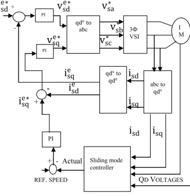
sq + - ActualREF. SPEED QD VOLTAGES
II. FIG 1:BLOCK DIAGRAM VIISIMULATIONDIAGRAMANDRESULT
Simulation is done for Induction motor drive speed control using sliding mode controller. The sliding mode controller block is designed with the help of above equations mentioned.
TABLE I: INDUCTION MOTOR PARAMETERS
Parameter Symbol Value
Rated Power pn 3730VA
Line-Line Voltage vn 460V
Rated Speed N 1750rpm
Frequency Fs 60Hz
Stator Resistance Rs 1.115ohm
Stator Inductance Lls 0.005974H
Rotor Resistance R′r 1.083ohm
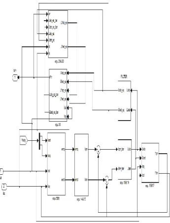
Rotor Inductance L′lr 0.005974H Mutual Inductance Lm 0.2037H Pole Pair P 2 PI PI PI qde to abc qde qds to 3Ф VSI abc to qds Sliding mode controller I M
An indirect field-oriented control (IFOC) scheme with a qde reference frame rotating at synchronous speed ωe is used for IM rotor speed control. Proportional–integral type controllers are used in the rotor speed control loop and in the qde stator current control loop. The parameters of the simulated IM machine are listed in Table 1. The designed algorithm gains are as follows: U0 = 400 and K = 80. Rotor speed reference
varies from 0 to140 rad/s.
Fig. 2: Simulation Diagram of Proposed System From Fig. 2 it is clear that, the induction motor speed is controlled by sliding mode controller and the gate pulse is given from three phase voltage source inverter with frequency of 2 KHz and input dc supply is of 650V( 2 ∗ 460𝑉) where, 460v is the motor rated voltage
.
The gate pluses are given by the voltage vectors. These voltages are estimated from the motor three phase current which is used to transfer abc reference frame to qd stationary reference frame which is then transformed into qd synchronously rotating reference frame. This q-axis current is compared with the reference current which is generated from the error detection of reference and actual speed which in turn gives the error signal which is then given to PI controller to generate q-axis voltage. The d-axis current is compared with reference whichis set as 0.3 and then to PI controller to generate d-axis current. The transformation of 2 phase to 3 phase is done in order to generate gate pulses for three phase voltage source inverter.
Fig. 3 Simulation Diagram of Sliding Mode Controller The output of sliding mode controller is the actual speed which is estimated from motor current and voltage as its input. The controller is designed with the help of above equations which is described in section VI.
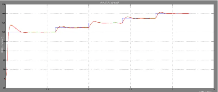
Fig. 4 Waveform of Output Voltage
Fig. 6 Waveform of Output Speed
Fig. 7 Waveform of Output Torque
VIIICONCLUSION
The efficient speed control of induction motor is need due to the large use of industrial applications. So, a new topology of Sliding mode observer with more efficient speed control is needed. In this work, a new Sliding mode observer with efficient speed control is designed. Sliding mode observer is a sensorless controller which reduces the cost of sensors and also reduces complexity in mathematical calculation. Sliding mode controller is designed by two steps, where first step is to design the sliding surface and the second step is to design the controller, which is carried out by mathematical equation of simple form. The output waveform of induction motor along with Sliding mode controller is simulated using MATLAB R2009a. Future work includes developing of a new controller for both speed and current based on Soft Computing Techniques such as Fuzzy PI controller instead of PI controller which gives more accuracy and easy tuning to get the desired output
.
REFERENCES
[1] Atkinson D. J., P. P. Acarnley and J. W. Finch, “Application of estimation technique in vector controlled inductin motor drives,” IEE Conference Proceeding, London, July 1990, pp. 358-363.
[2] Chan C. C., Leung W. S. and C. W. Nag, “ Adaptive decoupling control of induction motor drives,” IEEE Transaction on Industrial Electronics, vol. 35, no. 1, Feb. 1990, pp.41-47
.
[3] Garces L. J., “Parameter adaptation for speed controlled static AC drives with a squirrel cage induction motor,” IEEE Transaction on Industry Applications, vol. 16, no. 12, Mar. 1980,pp 173 -178. [4] Hung K. T., and R. D. Lorenz, “ A rotor flux error based adaptive
tuning approach for feed forward field oriented induction machine drives,” IEEE Conference, record IAS annual meeting, 1990, pp. 594-598.
[5] Bose B.K.,”Modern Power Electronics and AC Drives”, Pearson Education, 4th Edition, 2004
.
[6] Chan, C. C., and H. Q. Wang, “New scheme of sliding mode control for high performance induction motor drives,” IEE conference Proceeding, on Electric Power Applications, vol.143, no. 3, May 1996, pp 177- 185. [7] Kim Y. R., S. K. Sul and M.H. Park, “Speed sensorless vector control of induction motor using extended Kalman filter,” IEEE Transaction on Industrial Applications, Vol. 30, no. 5, 1994, pp. 1225-1233. [8] Qiao Z, T. Shi, Y. Wang, Y. Yan, C. Xia, and X. He, “New sliding
mode observer for position sensorless control of permanent-magnet synchronous motor,” IEEE Transaction on Industrial Electronics, vol. 60, no. 2, pp. 710–719, Feb. 2013
.
[9] Yang J, S. Li, and X. Yu, “Sliding-mode control for systems with mismatched uncertainties via a disturbance observer,” IEEE Transaction on Industrial Electronics, vol. 60, no. 1, pp. 160–169, Jan. 2013.
[10] Kim H, J. Son, and J. Lee, “A high-speed sliding-mode observer for the sensorless speed control of a PMSM,” IEEE Transaction on Industrial Electronics, vol. 58, no. 9, pp. 4069–4077, Sep. 2011.
[11] Tajima H. and Y. Hori, “ Speed sensorless field oriented control of induction machine,” IEEE Transaction on Industrial Application, vol. 29, no. 1, 1993, pp.1003-1008
.
[12] Benchaib, A., A. Rachid, and E. Audrezet, “ Sliding made input-output linearization and field orientation for real time control of induction motors,” IEEE Transaction on Power Electronics, vol. 14, no.1, Jan 1999, pp.128- 138.