Design of an Integrated Active Front Steering and
Active Rear Differential Controller using Fuzzy
Logic Control
Samaneh Arabi, Mohammad Behroozi
Abstract 1— An integrated vehicle dynamic control system for a vehicle with an active front steering (AFS) and active rear differential (ARD), based on fuzzy logic control, is developed to improve the vehicle stability and its handling performance. The controller structure is consisted of two layers in a hierarchical arrangement. A fuzzy logic controller is used in the upper layer to keep the yaw rate in its desired value. The yaw rate error, lateral acceleration and the side slip angle are applied to the upper controlling layer as the inputs, where the desired traction torque transfer ratio and the steering angle correction of the front wheels are the outputs. However, the ideal control effectors could not be directly the control inputs for the rear differential. Therefore, in the lower control loop, one should map the ideal control effectors to the physical control inputs for the rear differential by optimum dynamic traction force distribution. A nonlinear eight degree-of-freedom (DOF) vehicle model with the traction force distribution being utilized by a PI controller is considered. The simulation results illustrate considerable improvements have been achieved for the vehicle stability and handling performance through the integrated AFS/ARD control system.
Index Terms: Active differential, Active front steering, Fuzzy logic control, Vehicle stability control.
I. INTRODUCTION
Recent researches introduce yaw rate control as one of the most important methods in vehicle stability in extreme maneuvers and also this strategy can avoid dangerous and undesirable behaviors in vehicles. Several references have addressed this strategy, which makes direct changes in the yaw moment to adjust yaw rate [1-3]. Most of these approaches are based on braking forces in wheels, but provide serious restrictions in the vehicle performance [4, 5].
To tackle this problem, active differentials have the capability of usage in yaw rate control systems to avoid decrease in vehicle performance during different maneuvers. The system works on the basis of varying
1
Manuscript received March 21, 2010.
Samaneh Arabi was with the Iran University of Science and Technology, Tehran, Iran, finished her M.Sc. on Automotive Engineering - Vehicle Dynamics and chassis - in 2009. (Mobile phone: +98-912-1891518; e-mail: [email protected]).
Mohammad Behroozi is with the school of Mechanical Engineering, The University of Birmingham, Birmingham, B152TT UK. He is currently doing his Ph.D. in Vehicle Technology Research Center (Phone: +44-121-4144167; e-mail: [email protected]).
traction forces on wheels, and therefore, will not have destructive effect on longitudinal response of vehicle. Intelligent differentials are much in demand with interest of public in vehicle safety. The control torque distribution on each wheel of vehicle system with one or two active differentials for safety driving have discussed by the numerous authors [6-8].
Another method to control the yaw moment is active steering which works on the base of lateral tire-force control through control of steering angle [9, 10]. The potential of active steering would easily be usable where the steer-by-wire (SBW) technology is established. Recently, a most practical approach to steering control is AFS in which a correction of steering angle is added to the driver’s steering input. More recently, active steering has been combined with the yaw rate feedback to robustly decouple the yaw and lateral motions [11]. Several projects have been conducted on control of steering angle accompanied by the braking force control as a way to improve the vehicle handling and stability [12, 13].
To enhance the ability in control of vehicle lateral dynamic performance, the usage of an integrated vehicle dynamics control system for vehicle by a combination of active front steering (AFS) and active rear differential (ARD) is proposed. In this study, a new approach to integrated control of AFS/ARD is developed. The control system has a hierarchical structure consisting of two layers. A fuzzy logic controller is used in the upper layer to keep the yaw rate in its desired value. The desired traction torque transfer ratio and the steering angle correction of the front wheels are the outputs. However, the ideal control effectors could not be directly the control inputs for rear differential. Therefore, in the lower control loop, one should map the ideal control effectors to the physical control inputs for rear differential by optimum dynamic traction force distribution. It would finally cause a sensible enhancement in tracking the desired path and increasing rear-wheel drive (RWD) vehicle stability.
computer simulation has been performed on an 8-DOF vehicle dynamic model to show the enhancements in the vehicle dynamics responses with the controllers.
II. MODEL DESCRIPTION
A. Eight DOF vehicle dynamic model
Since this research is focused on investigating how to improve the vehicle stability and performance by dynamically distribution of the torque on rear wheels and control of steering angle, mathematical analysis and modeling of RWD vehicle with active differential are necessary. A comprehensive eight DOF vehicle dynamic model is illustrated in Fig. 1 [14]. These include the longitudinal velocity u, lateral velocity v, yaw rate r, roll rate p, and the rotational speed of wheelsw i .
The model includes nonlinearities of the system, such as the nonlinear behavior of tires, nonlinearities exist in the longitudinal and the lateral tire normal load transfers, the roll steer effects, and the camber angle changes due to the vehicle roll. The model has been primarily developed as a tool for the vehicle dynamic computer simulation.
The four governing equations of motion are organized for the longitudinal and lateral motions along the X and Y axes, respectively, and the corresponding rotational motions of the yaw and roll about the Z and X axes.
2 / sin 2 4 1 u A C mg F
ma d f a
i i x
x
(1)
4 1 i i y syu m hp F
ma (2)
1 3 2 4 1 2
3 4
( ) ( ) ( ) / 2
( ) / 2
zz y y y y x x
x x
I r a F F b F F F F T
F F T
(3)
.sin (4)
xxs s yu s
I pm h a m gh KC (4)
Fig.1. the 8-DOF vehicle handling model [14]
Where
is the roll angle of the sprung mass about theroll axis and
a
x anda
yuare the longitudinal acceleration of the vehicle and the lateral acceleration of the unsprung mass.vr
u
a
x
,a
yu
v
ur
(5)The terms
i
x
F and
i y
F are the respective tire forces in
the X and Y directions, which could be expressed as functions of the traction and lateral tire forces with
Ti
being the steering angle.
cos sin 1,.., 4
x i t i Ti s i Ti
F F
F
i (6)sin cos 1,.., 4
y i t i T i s i Ti
F F F i (7)
4 ,..., 1 . T T F dF R i
Iwi
i ti bi zi xi (8)The normal loads on wheels are mostly used in the modeling process of tires. Using the quasi-static lateral and longitudinal load transfer, the normal load expression for each wheel could be written as
1
2
3
4
( ) [ ( ) ( )( )sin ] 2
( ) (1 )[ ( ) ( )( )sin ] 2
( ) [ ( ) ( )( )sin ] 2
( ) (1 )[ ( ) ( )( )sin 2 y s x s z R y s x s z R y s x s z R y s x s z R a a m
W b h h h
F K
l g l g T m T
a
a m
W a h h h
F K
l g l g T m T
a
a m
W b h h h
F K
l g l g T m T
a
a m
W a h h h
F K
l g l g T m T
] (9)
Where KR is the front roll stiffness ratio that
determines the front/rear distribution of the total lateral
load transfer, and aysis the lateral acceleration of the
sprung mass as
(
/ )
ys s
a
v ur
m
m h p
(10) The expression for the slip angle of each wheel, as a function of the variables, can be written as) arctan( 2 1 1 1 Tr u ar v T
(11) ) arctan( 2 1 2 2 Tr u v br T
(12) ) arctan( 2 1 3 3 Tr u v ar T
(13) ) arctan( 2 1 4 4 Tr u v br T (14)Furthermore, the vehicle side slip angle is defined as
arctan( / )
v u
(15)The tire model which has been used in this handling model is known as “Combined Slip Magic Formula” in the non-linear tire model, [15]. The tire model calculates the traction and lateral tire forces of each wheel based on its slip angle, the normal force, and the longitudinal slip.
B. Rear Limited Slip Differential
A schematic diagram of two clutches which represent electric limited slip differential is shown in Fig.2. Let us define TLSDR and TLSDL to be the torque transferred
through the right clutch and left clutch, Tdiffis the torque
that is equally distributed to the left and right axle and transferred through the differential gear. If we assume efficiency of the torque is 100 % and differential has no mass inertia, we will have
LSD-R rear LSD-L rear diff rear r
(T ) +(T ) +(T ) =T
dr (16)( ) 1
( ) [ ( ) ]
2 2
diff rear
rr LSD R rear r dr LSD R LSD L rear
T
T T T T T (17)
( ) 1
( ) [ ( ) ]
2 2
diff rear
rl LSD L rear r dr LSD R LSD L rear
T
T T T T T (18)
Fig.2. Front and Rear Limited Slip Differential
Distribution of traction torque to the right and left axle
is defined to the left-right ratio parameter (
LR) andaccording above equation it can be obtained as function of
T
LSDandT
r.rl rr
rr R L
T
T
T
(19)(
)
(
)
1
(
)
[1
]
2
LSD L rear LSD R rear L R rear
r dr r dr
T
T
T
T
(20)
Assuming zero inertia, clutch in electric limited slip differential can be modeled as a spring-damper torsional element [6].
(
T
LSD R rear)
c
.[(
diff rear)
rr]
k
.[(
diff rear)
rr]
dt
(21)dt k
c
T rl
rear diff rl
rear diff rear L
LSD ) .[( ) ] .[( ) ]
(
(22)III. CONTROL SYSTEM STRUCTURE
The structure of proposed integrated control system is shown in Fig.3. The control system has a hierarchical structure consisting of two controlling layers. The upper layer is the yaw rate controller which is designed on the bases of fuzzy logic strategy. The outputs of the upper controller are the desired traction torque transfer ratio
(*LR) and the steering angle correction of the front
wheels (Cor) which are applied as the controlling
inputs.
In this method, by applying independent traction torques on rear wheels through rear differential, the required yaw moment is generated to correct the vehicle dynamic behaviour. This control method will be effectively useful under extreme cornering manoeuvres. An FLC is therefore designed as an upper layer in hierarchical controller to come up vehicle guidance strategy in dangerous maneuvers. The controller structure is indicated in Fig.3.
This upper control loop is used to calculate the ideal control effectors (*LR) which is required for realizing
the steady and dynamic characteristics of the control system. However, the ideal control effectors could not be directly the control inputs for the rear differential.
Therefore, in the lower control loop, one should map the ideal control effectors to the physical control inputs for the rear differential by optimum dynamic traction force distribution. The traction force distribution is implemented by a PI controller.
Fig.3. Block diagram of the proposed control system
It would be assumed that the vehicle control system is a rear wheel drive vehicle with a limited slip differential and can be used to transfer torque from the left to the right wheel as well as reverse direction. On the other hand, the correction steering angle is added to the driver’s
steering input, and this task is simply accomplished if
the vehicle is equipped with a steer-by-wire (SBW) system.
In this study, the inputs of the fuzzy controller are side-slip angle, lateral acceleration and the difference between actual yaw rate value (yaw rate (r) of 8-DOF vehicle
model) and the target value rR, i.e.,er which are
described as
r
r
e
r
R
(23)Upper controller outputs are the desired traction torque transfer ratio (*LR ) and the steering angle correction
of the front wheels Cor After integration of
dt
d(Cor) , the inner and the outer steering angles are
finally calculated
dt dt d
i
t t
Cor
In
0
)
(
(24)
dt dt d i t t
Cor
Out
0
)
(
(25)
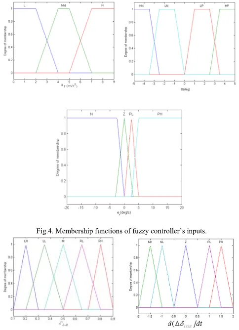
A possible choice of the membership functions for the six mentioned variables of the system represented by a fuzzy set is as follows:
For side slip angle: HN (High Negative), LN (Low Negative), LP (Low Positive), HP (High Positive); For lateral acceleration: L (low), Mid (Mid), H (High), For yaw rate error: N (Negative), Z (Zero), PL (Positive Low), PH (Positive High); steering angle correction of
the front wheels (Cor):(Negative High, Negative Low,
Zero, Positive Low and Positive High); and desired traction torque transfer ratio for rear differential*LR:
Fig.4. Membership functions of fuzzy controller’s inputs.
Fig.5. Membership functions for fuzzy controller’s output.
By using the fuzzy control theory, the outputs are calculated based on appropriate fuzzy rules. The rule base used in the system can be represented by the following table with fuzzy terms derived by modeling the designer’s knowledge and experience. The linguistic control rules of the fuzzy logic controller obtained from the Tables 1 and 2 used in general form of:
) ) ( (
) ( ) ( ) (
: *
i COR i R L i r i y i
i IF A ANDa B ANDe C THEN D d dt E
R
WhereAi,Bi,Ci, Di and Ei are labels of fuzzy sets
representing the linguistic values of β,ay,er, *LRand
dt
dCOR respectively, which are characterized by their
[image:4.612.343.522.69.174.2]membership functions.
Table 1. Fuzzy inference rules for
*LRr
e
y
a
(degree) N Z PM PH
LL LL LL LL Low High
Negative High Mid LH LH LH LH LL LH LH LL RH RL M M Low Low
Negative High Mid LL LL M M RH RH RH RH LH LL M M Low Low
Positive Mid RL M LH LH LH LH M RL High
RL RL RL RL Low High
positive Mid RH RH RL RL RH RH RH RH High
Table 2. Fuzzy inference rules ford(COR dt)
r
e
(degree/sec)y
a
(degree) N Z PL PH
PH PL Z NL Low
Low Mid NL Z PL PH
PH PL Z NH High
NL NL NH NH Low
High Mid NH NH NH NH
NH NH NH NH High
In the event that side-slip angle is provided in the desired region, the controller tracks the reference model yaw rate, and in case the side-slip angle exceeds the boundary of the desired region, the FLC forces the vehicle to move to safe and desired region of yaw rate. The control strategy is based on the following facts:
When vehicle is cornering in high lateral acceleration
and yaw rate error is negative, the vehicle is over-steered. In this case, FLC will order to transfer traction torque toward wheel located inside corner by rear differential, and also increase the steering angle of the inner wheel and decrease the steering angle of the outer wheel, which can decrease the front axle's total lateral force and leads to more stability.
In severe understeering condition, the yaw rate error
is positive when the side slip angle β is still in the
safe region. To improve the vehicle handling and the yaw rate following characteristic, by increasing steering angle of the outer wheel and decreasing the steering angle of the inner wheel, one could increase the total lateral force applied on the front axle. The traction torque is transferred to the outside corner wheel to generate more lateral force in the event that yaw rate error is positive, the vehicle is in less under-steer situation than reference model and side-slip angle is in the desired region.
In the situation that the side-slip angle is not in the
desired region, the control objective is just set to decrease the side-slip angle and consequently, the traction torque of rear inside corner wheel and inner front wheel steering angle increase.
In this study the Mamdani algorithm is employed for the fuzzy logic operation and the Gravity algorithm is utilized for the calculation of the defuzzification.
[image:4.612.95.264.567.713.2]
Fig.6. Lower control loop
[image:4.612.337.523.574.630.2]This value is then fed into the 8-DOF model of RWD vehicle. The equation of the PI controller can be expressed as
R
K
pK
Idt
L
.
(26)WhereKpis the P gain, KIgain the I gain, and is
given as
R L R L
*
(27)The traction torque of each rear wheels can be expressed from equations (19) – (22).
IV. NUMERICAL SIMULATION AND ANALYSIS
Computer simulation of the system is performed to evaluate the performance of the integrated control of the AFS/ARD as an intelligent control system.
An increase in the traction force on the rear inner wheel and steering angle of front inner wheel, as can be seen from Fig.8, would generate the turning moment in the counter clock-wise (CCW) direction. As a result of generating a CCW turning moment, the stability tendency of the vehicle moves toward the understeered case and the side slip angle is decreased.
a- Steering angle b- Side slip angle
c- Lateral acceleration d- Yaw velocity
e - TLSD of rear active differential f- Steering angle on front tires
Fig.8. Yaw rate control.
The simulation case study consists of a high lateral acceleration lane change maneuver at speed of 30 m/s on a
road with friction coefficient
Road
0
.
9
. In simulation,the lane change maneuver is completed in 2 seconds with
two pulses (δ = ±4 deg) as it is shown in Fig.7-a. The
vehicle is considered to be inherently oversteered and the simulation results are illustrated in Fig.7. It is evident from Fig.7-b, that the side slip angle of the uncontrolled vehicle grows rapidly and the vehicle shows a strong oversteered behavior. However, in the case of the controlled vehicle, the side slip angle has been effectively controlled well below the acceptable limit to intelligently control of the steering correction angles and the distribution of traction torque. It can be seen that integrated AFS/ARD has better performance and decreases the value of side-slip angle to 3.5deg by transferring 90% of the traction torque to the rear inner wheel; and also increases the front inner steering angle and decreases the front outer steering angle. In this case, the side slip control is the first priority of the control system.
V. CONCLUSION
In this paper, an integrated dynamic control system AFS/ARD which aims to improve vehicle handling and stability without interfering in vehicle performance has been designed. The proposed control system includes two layers. A fuzzy logic controller is used in the upper layer to keep the yaw rate in its desired value and the lower control loop maps the ideal control effectors to physical control inputs for rear differential by optimum dynamic traction torque distribution.
In accordance with the simulation results, the integrated controller (AFS/ARD) could intelligently control the steering angle while active differential device employs appropriate traction force combinations in various conditions. It can provide the best possible yaw rate following performance while keeping the side slip angle as low as possible to simultaneously guarantee the safety and stability of the vehicle. This mitigates the vehicle’s oversteering or understeering tendencies while the vehicle is undergoing with dangerous cornering situation.
It also compares the feasibility and effectiveness of the individually AFS system with respect to the conventional systems with no controllers. Due to the capacity of actuators
and control strategy the integrated AFS/ARD controller showed better capabilities than AFS to guide the vehicle to safe region of side-slip angle – owing to AFS limitations in membership function of side-slip angle (Fig.10b) and its capacity to generate proper steer angle, vehicle cannot be severed by AFS lonely even though a couple of changes is provided in applied steer angle of which effects is not serious.
REFERENCES
[1] Goodarzi, A., Nadarkhani, B., Esmailzadeh, E. 2003 “Direct yaw moment controller design for vehicle dynamic control system”, IASTED International Conference on Modelling, Simulation and Optimization, pp. 120-124, Banff, Canada, July 2-4.
[2] Cong, G., Mostefai, L., Denai, M., Hori, Y. 2009 “Direct yaw moment control of an in-wheel-motored electric vehicle based on body slip angle fuzzy observer”, IEEE Trans. on Industrial Electronics, 56(5), 1411-19.
[3] Boada, B.L., Boada, M. J. L., Díaz, V. 2005 “Fuzzy-logic applied to yaw moment control for vehicle stability”, Vehicle System Dynamics,
43(10), 753–70.
[4] Khatun, P., Bingham, C.M., Schofield, N., Mellor, P.H. 2003 “Application of fuzzy control algorithms for electric vehicle antilock braking/traction control systems”, IEEE Vehicular Technology,
52(5), 1356-64.
[5] Yi, K., Chung, T., Kim, J., Yi, S. 2003 “An investigation into differential braking strategies for vehicle stability control”, J. Automotive Engineering, 217, 1081-93.
[6] Piyabongkarn, D., Lew, J., Rajamani, R., Grogg, J.A., Qinghui Y. 2007 “On the use of torque-biasing systems for electronic stability control”, IEEE Trans. on Control Systems Technology, 15(3),
403-598.
[7] Osborn, R.P., and Shim, T., 2004, “Independent control of all-wheel-drive torque distribution”, SAE Technical Paper,
No.2004-01-2052.
[8] M. Canale, L. Fagiano, M. Milanese, and P. Borodani, Robust vehicle yaw control using an active differential and IMC techniques , Control Engineering Practice 15 (2007), pp. 923–941.
[9] Goodarzi, A., Esmailzadeh, E., Nadarkhani, B. 2006 “Design of an optimal control strategy for an active front steering system”, Proceedings, ESDA 8th Biennial Conference on Engineering Systems Design and Analysis, July 4-7, Torino, Italy, Paper # 95577. [10] Goodarzi, A., Rahiminejad, D., Esmailzadeh, E. 2009 “Design of a
fuzzy controller for independent control of front wheels steering angle”. Proceedings, ASME International Design Engineering Technical Conference, San Diego, California, August 30-September 2.
[11] Ackermann, J. 1996 “Yaw disturbance attenuation by robust decoupling of car steering”, Proceedings, IFAC World Congress, San Francisco, USA, June 30-July 5.
[12] Goodarzi, A., Alirezaie, M. 2006 “A new fuzzy-optimal integrated AFS/DYC control strategy”, Proceedings, 8th International Symposium on Advanced Vehicle Control (AVEC), Taipei, Taiwan, August 20-24.
[13] Nagai, M., Shino, M., Gao, F. 2002 “Study on integrated control of active front steer angle and direct yaw moment”. JSAE Review, 23, 309-15.
[14] Esmailzadeh, E., Vossoughi, G.R., Goodarzi, A. 2001 “Dynamic modelling and analysis of a four motorized wheels electric vehicle”,
Vehicle System Dynamics, 35(3), 163-94.