Please cite this article as: M. Akhondizadeh, V. Khalili, Effect of Material Wet on Silo Obstruction Solution by Impact, International Journal of Engineering (IJE), TRANSACTIONS B: Applications Vol. 29, No. 11, (November 2016) 1628-1634
International Journal of Engineering
J o u r n a l H o m e p a g e : w w w . i j e . i r
Effect of Material Wet on Silo Obstruction Solution by Impact
M. Akhondizadeh*, V. Khalili
Mechanical Engineering Department of Sirjan University of Technology, Sirjan, Iran
P A P E R I N F O
Paper history: Received 02 July 2016
Received in revised form 08 August 2016 Accepted 30 September 2016
Keywords: Laboratory Silo Impact Obstruction Wet
Vertical Pressure Granular Materials
A B S T R A C T
Vertical silos are large cylinders used for material storage in agriculture and mineral industries. One of the silo problems is its obstruction due to dome and dense packing. Depend on the material properties and silo dimensions several techniques are used to solve this problem. In the present work, possibility of obstruction solution of a laboratory silo by ball impact is investigated. Test materials are magnetite and hematite concentrate and reproducible hematite, having specified wet. Ball impacts fracture the bulk and make it to flow. The profile of fractured regime is captured and the required number of impacts which provide the continuous flow are registered. Results show that different materials do not have the identical behavior during ball impacts. Moreover, it has been revealed that as the wet increases, the obstruction intensity increases and more impacts are required. Results will be used to optimum impactor be designed for obstruction solution of operating silos in Gol-e-Gohar iron ore complex.
doi: 10.5829/idosi.ije.2016.29.11b.18
1. INTRODUCTION1
One of the silo flow problems is obstruction due to arching or cohesiveness. Obstruction relates material flow on silo outlet and occurs due to arching. The cause may be the bridging by large particles or cohesive arcs. However, there is a strategy for silo design in order to prevent its obstruction [1] but in some cases material sizing and moisture will cause problems in discharge [2]. Karimi et al. [3] illustrated that the material wet may be changed within the metabolism of products. A critical value for silo outlet can be evaluated to prevent the obstruction at the specified particle size and moisture. Mathews and Wu [4] investigated the effects of gravity on material flow at discharge and internal patterns using a centrifuge model of silo. They illustrated that the flow channel size does not depend on the gravity and material velocity is proportional to the acceleration of gravity. They also stated that the criteria for funnel or mass flow conditions are independent of gravity. As reported by Roberts [5], quaking is known to occur in tall mass- flow silos in which the height of
1*Corresponding Author’s Email: [email protected]
(M. Akhondizadeh)
fill is above a critical height. In order to predict the rate of silo discharge, Beverloo [6] developed a correlation based on easily measurable silo and material properties. The Beverloo correlation was modified by Mathews and Wu [4] for rectangular outlets by maintaining dimensional consistency and considering that the flow rate increases linearly with silo thickness.
Schulze and Schwedes [7] used a test silo to effectively compare various analytical methods with data obtained empirically for vertical and normal stresses during filling and before discharging in hoppers. They found that a reasonable degree of accuracy could be obtained using popular slice element methods. Accuracy could be increased with manipulation of various factors within the calculations to better suit prevailing conditions. However, it was commented that these methods, including Walters [8] and Motzkus [9], did not take into account various conditions affecting the material. Factors such as compressibility and deformation of the bulk solid were not considered. Hence, Schulze and Swedes [7] suggested a new method to take account of such factors. Schulze [7] discussed a method of obtaining a granular materials yield locus. The method used was the uni-axial compression test. According to Bates, the second parameter of primary importance for
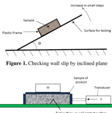
gravity flow is wall friction measurement. This can be achieved by the simple test set up shown in Figure 1. However for more accurate data, or where surface adhesion is present, Bates recommends use of the set up shown in Figure 2.
In summary, it seems that although there are many experimental data in this field, advances are still possible. Experiments may not be conducted in identical conditions to that of actual usage of the granular material. For example, it has been proven that yielding of granular material can be time dependant [10]. Freeman [11] presented modern items of test equipment in order to provide repeatability by conditioning samples of powder prior to testing. Nateghi and Yakhchalian [12] showed that the seismic behavior of grain material is highly nonlinear. It justifies using the laboratory silos, instead of theoretical methods, to study the grain material behavior. The processes concerning the impact phenomenon, because of their complicated manner, require the empirical procedures to be evaluated [13].
A silo in Gol-e-Gohar iron ore has the obstruction problem which makes it out of order. A comprehensive study is currently undertaken to investigate one individual procedure or simultaneously multiple ways to solve the problem. In the present work, as a part of this research, the ability of ball impact for obstruction solution of different materials having different wet is investigated. The novelty is that the parameters directly relate to the yielding of grain materials are studied here. These parameters include material type, internal friction and wet.
2. PROBLEM DESCRIPTION
A silo may be initially well designed but over a period of operation variation of material moisture and particle
Figure 1. Checking wall slip by inclined plane
Figure 2. Wall friction test with force measuring device
size causes unstable material discharge. In critical state, it may results in silo malfunction and make it out of order. Test silos are usually much smaller than the operating ones used in industry. Full scale testing is uncommon due to the time and expense required. A usual problem is silo obstruction and a common solution is silo wall actuation by impacts. Impator may be large hand-pendulum or small pneumatic hammers. Ability of this procedure depends on the material and wall properties. This is investigated here by impacting the hopper wall of a laboratory silo for three material types: hematite and magnetite concentrate and hematite reproducible. Effect of material wet is also investigated.
3. LABORATORY SILO
Since cylindrical silos are huge structures, it is practically impossible to carry out experiments on operating silos. On the other hand, theoretical methods don't give the reliable predictions for the behavior of grain materials. Because of these, using the scaled silo is an acceptable way to investigate grain behaviors. Many researchers used such scaled silos for this aim [14-16]. Laboratory silo made of 6 mm thick polexy glass. It is supported by a box structure. The bottom is about 600mm above the ground. The hopper is wedge-shape cone with 100mm in width orifice. Schematic and an image of this silo have been illustrated in Figure 3. Parameters of Figure 3 are given in Table 1.
4. EXPERIMENTAL PROCEDURE
Behavior of different materials and the effect of wet on response to ball impacts are investigated here. Materials are hematite and magnetite concentrate and reproducible hematite. Shear tests are performed to determine the internal friction. Silo is filled while its outlet is closed by a flat plate. Foundation has been such designed to have minimum fluctuations in order to minimize testing errors. If there is no material discharge, after the silo outlet is opened, the impacting process begins. It is allowed, after a single impact, to partial discharge be completed and stationary condition occurs again. The new material profile in hopper is captured and the impacting process is repeated. This is done until the continuous flow occurs, the stationary condition doesn't occur again, and the silo be completely discharged. This will be the end of a test. As an obligation here, maximum of 5 impacts on each individual wall is conducted. If the continuous flow is not achieved, another wall is impacted afterward.
Figure 3. Schematic and image of laboratory silo
TABLE 1. Laboratory silo dimensions
H(mm) h(mm) D(mm) d(mm)
300 200 250 100
material to increase the internal pressure.
Impact parameters include the ball size, ball velocity and impact position which are important in the study but they are not the topic of the present work. Here, the fixed impact parameters are selected for all tests. The ball is 25mm in diameter, impact velocity is 2.5m/s and impact position is 40 mm above the silo outlet. Due to the limitation of the page numbers for the present paper the effect of impact parameters will be submitted in another paper.
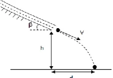
Gravity acceleration is employed to achieve ball velocity. A hose is used for this aim in which the ball potential energy is converted into kinetic energy. To measure the ball velocity, a pre-experiment is conducted before the main impacting tests. Horizontal and vertical ball displacements, q and h2 in Figure 4, are measured and the ball velocity at hose exit is evaluated using the free falling relation as follow:
(1)
In which, g is the gravity acceleration and other parameters are given in Figure 4.
5. BULK BEHAVIOR DUE TO IMPACT
One of the important flow property is the bulk strength of granular material. In order to reliably achieve flow, stresses within the material must reach yield [17].
Figure 4. Schematic of the procedure of ball velocity measurement
Arching can occur in two forms: cohesive arching and mechanical blockage. Cohesive arching occurs only with cohesive materials whereby an arch of material forms above the silo outlet, able to support the weight of material above [16]. It means that the granular elements are in static equilibrium under the effect of the body and surface forces. The gravity provides the dominant body force which governs the material flow in silo. Surface forces include normal and shear stresses due to internal pressure, friction and cohesive effects. Schulze [17] goes on to represent the uni-axial compression test on a σ-τ diagram in Figure 5. B1, B2 and B3 are the Mohr's circles corresponding to the different states of stress in material. If a state of stress be below the yield locus the material is on stationary state and if be the above of it material will be ruptured. C is the threshold of yield and D is over yield.
Granular element remains in equilibrium until the state of stress is below the yield locus. Ball impact displaces the hopper wall and disturbs the internal state of stress. Wall undergoes a reciprocating motion results in a compact-expansion. The pressure is removed or is weaken instantly during expansion which results in bulk fracture. Schematic of fracture boundary after impact has been illustrated in Figure 6.
In this figure, region A is the region in which the discharge occurs during a single impact. The material in region B is still in equilibrium and more impacts are required for bulk fracture.
Shear tests have been carried out to determine the granular internal friction. A conventional direct shear apparatus, as illustrated in Figure 2, was used for this aim. The coefficient of internal friction corresponding to different wet is given in Table 2.
6. RESULTS AND DISCUSSION
The outlet of filled silo is opened and the impacting process begins if there is no material discharge. The first wall is impacted by maximum 5 single impacts. If there is no continuous flow the second, third and fourth walls are impacted. If the continuous flow doesn't occur after 5 impacts on fourth wall the test ends and impacting fails to solve the obstruction for that condition. Before this step, whenever the continuous flow occur the test ends. Since each experiment is repeated 3 times and the following results correspond to the average values of impact numbers, there are decimal values in graphs. In following figures the experiments with a weight on top of silo are said with weight experiments and those without this weight are said without weight.
It can be seen that the wet increment has the evident effect on silo obstruction. No impact is required to discharge 0% wet hematite and so on 0% and 5% reproducible hematite. It means that the material flow occurs as the silo outlet is opened.
Figure 6. fracture boundary of bulk after impact, Material flow occurs in region A and still stable material in region B
TABLE 2. Material properties
Hematite Magnetite Reproducible Hematite
Grain size (mm) +0.1-3 +0.1-3 +.1-3
Internal friction
(0% wet) 0.069 0.139 0.135
Internal friction
(5% wet) 0.109 0.073 0.103
Internal friction
(10% wet) 0.107 0.070 0.09
Density (kg/m3) 2300 2500 2000
Figure 7. Required impact numbers to occur the continuous flow of magnetite concentrate of different wet
Figure 8. Required impact numbers to occur the continuous flow of hematite concentrate of different wet
Figure 9. Required impact numbers to occur the continuous flow of 10% wet reproducible hematite
0 1 2 3 4 5
1 2 3 4
5
3
0 0
4.6
1
0 0
N o . O f im pa ct s Wall
Magnetite 0% With weight
without weight 0 1 2 3 4 5
1 2 3 4
5
4 3.2
2.5
5 5
0 0
N o . o f im pa ct s wall
magnetite 5% With weight
Without weight 0 1 2 3 4 5
1 2 3 4
5 5 5 5 5 5 5 5
N o . o f im pa ct s wall
Magnetite 10% Wiyhout weightWith weight
0 1 2 3 4 5
1 2 3 4
5
4
2.5 2.5
5
1.3
0 0
N o . o f im pa ct s Wall
Hematite 5% With weight Without weight 0 1 2 3 4 5
1 2 3 4
5 5 5 5 5
3.6 3.3 3.3
N o . o f im pa ct s Wall Hematite 10% With weight Without weight 0 1 2
1 2 3 4
1.6
0 0 0
0 0 0 0
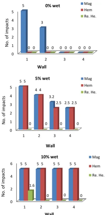
By increasing wet, the hematite is going to be more cohesive and the required number of impacts increases. It is more evident in the case of magnetite. Comparison of required impact numbers for three materials with weight and without weight is given in Figures 10 and 11, respectively.
These results show that the impact process has the low ability for the magnetite concentrate, especially in
maximized wet. The obstruction problem of
reproducible hematite is well solved using the ball impacts. The positive point of the present experiments is that we have the practical cases corresponding to some experiments in the Gol-e-Gohar complex. There are several silos in this complex that contain different iron ore by different wet. From the comparison point of view, for the behavior of different materials, identical behaviors can be seen between the scaled laboratory silo and operating silos. About the effect of wet, it has been seen that for more material wet lower continuous flow occurs.
Figure 10. Required number of impacts for continuous discharge of hematite (Hem), magnetite (Mag) and reproduced hematite (Re. He.), with weight
Figure 11. Required number of impacts for continuous discharge of hematite, magnetite and reproduced hematite,
without weight
There are several techniques including the air pulse, hand-pendulum impact, solid spiral pump and small periodic hammers to solve the silo obstruction. Results of present work show that the material properties such as wet should be considered in selecting a technique. Reproducible hematite basically flows without any mechanism. The obstruction of reproducible hematite and 0% wet hematite doesn’t occur at all. The obstruction for 0% wet magnetite and 5% wet hematite can be solved by several impacts at the case of with and without weight. More impacts are required for 5% wet magnetite and 10% wet hematite without weight. The impact is not an appropriate technique for obstruction solution of 5% wet magnetite with weight, 10% wet hematite with weight and 10% wet magnetite with and without weight.
The internal pressure in silo and hopper, based on coordinate illustrated in Figure 12, can be evaluated using the Janssen [18] relations as follow:
(2) 0 1 2 3 4 5
1 2 3 4
5
3
0 0
0 0 0 0 0 0 0 0
N o . o f im pa ct s Wall
0% wet Mag
Hem Re. He. 0 1 2 3 4 5
1 2 3 4
5 4 3.2 2.5 5 4
2.5 2.5
0 0 0 0
N o . o f im pa ct s Wall
5% wet Mag
Hem Re. He. 0 2 4 6
1 2 3 4
5 5 5 5 5 5 5 5
1.6
0 0 0
N o . o f im pa ct s Wall
10% wet Mag
Hem Re. He. 0 1 2 3 4 5
1 2 3 4 5
4.6
1
0 0
0 0 0 0 0 0 0 0 0
N o . o f im pa ct s Wall
0% wet mag.
hem Re. He. 0 1 2 3 4 5
1 2 3 4
5 5
0 0
5
1.3
0 0
0 0 0 0
N o . o f im pa ct s Wall
5% wet Mag
Hem Re. He. 0 1 2 3 4 5
1 2 3 4
5 5 5 5 5
3.6 3.3 3.3
0 0 0 0
N o . o f im pa ct s Wall
10% wet Mag
[
( ) ] (3)
In which, Ps and Ph are the silo and hopper pressure respectively, ρ is the material density, μw is the material-wall friction coefficient, k is the Janssen coefficient, g is the gravity acceleration, Ps2 is the silo pressure at z=h and other parameters are illustrated in Figure 3. k1 is a parameter which is evaluated as follow [19]:
(4)
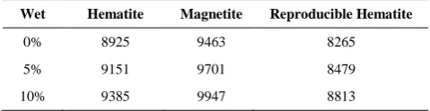
where, μi is the internal friction, ϴ is the hopper wedge angle and m=1 for tapered hopper and m=0 for wedge shaped hopper [20]. Maximum silo pressure is given in Table 3. It can be seen that in all cases the vertical pressure of magnetite is higher than of hematite and reproducible hematite. It may be a cause of its resistance to the impact in obstruction solution tests. The internal pressure is an important factor which intense the obstruction. As the internal pressure increases, greater shear force is required to fracture the granular layers and provide the material flow.
TABLE 3.Maximum vertical pressure in silo (pa)
Wet Hematite Magnetite Reproducible Hematite
0% 8925 9463 8265
5% 9151 9701 8479
10% 9385 9947 8813
7. CONCLUSIONS
Laboratory silo is used to investigate the effect of wet of three materials on obstruction solution.
Results show that the wet has an undeniable effect on silo obstruction
Magnetite concentrate is a cohesive soil which more impacts are required to discharge it.
Reproducible hematite discharges without any impact and rarely has obstruction.
Vertical pressure evaluations confirm that it is a factor that amplifies the silo obstruction
8. REFERENCES
1. Gallego, E., Ruiz, A. and Aguado, P.J., "Simulation of silo filling and discharge using ansys and comparison with experimental data", Computers and Electronics in Agriculture, Vol. 118, (2015), 281-289.
2. Garcia, M.C., Feise, H., Strege, S. and Kwade, A., "Segregation in heaps and silos: Comparison between experiment, simulation
and continuum model", Powder Technology, Vol. 293, (2016), 26-36.
3. G, K., M, T. and M., Y., "A numerical modeling for natural convection heat transfer in porous media with generated internal heat sources.", International Journal of Engineering, Vol. 4, No. 3&4, (1991), 115-126.
4. Mathews, J. and Wu, W., "Model tests of silo discharge in a geotechnical centrifuge", Powder Technology, Vol. 293, (2016), 3-14.
5. Roberts, A., "Review of the" silo quaking" problems in bins of various geometrical shapes and flow patterns", TASK Quarterly:
Scientific Bulletin of Academic Computer Centre in Gdansk,
Vol. 7, No. 4, (2003), 623-641.
6. Beverloo, W., Leniger, H. and Van de Velde, J., "The flow of granular solids through orifices", Chemical Engineering
Science, Vol. 15, No. 3, (1961), 260-269.
7. Schulze, D. and Schwedes, J., "An examination of initial stresses in hoppers", Chemical Engineering Science, Vol. 49, No. 13, (1994), 2047-2058.
8. Walters, J., "A theoretical analysis of stresses in axially-symmetric hoppers and bunkers", Chemical Engineering
Science, Vol. 28, No. 3, (1973), 779-789.
9. Motzkus, U., "Belastung von siloböden und auslauftrichtern durch kornige schuttguter, Technischer Universitat Carolo-Wilhelmina, (1974).
10. Nedderman, R.M., "Statics and kinematics of granular materials, Cambridge University Press, (2005).
11. Freeman, R., "Measuring the flow properties of consolidated, conditioned and aerated powders—a comparative study using a powder rheometer and a rotational shear cell", Powder
Technology, Vol. 174, No. 1, (2007), 25-33.
12. Nateghi, F. and Yakhcbalian, M., "Seismic behavior of silos with different height to diameter ratios considering granular material-structure interaction", International Journal of
Engineering, Vol. 25, No. 1, (2012), 27-37.
13. Korrani, M.A., Mahani, M.F., Rezaeizadeh, M. and Mansouri, S., "A new procedure of impact wearevaluation of mill liner (research note)", International Journal of
Engineering-Transactions A: Basics, Vol. 28, No. 4, (2015), 593-561.
14. Zuriguel, I., Pugnaloni, L.A., Garcimartín, A. and Maza, D., "Jamming during the discharge of grains from a silo described as a percolating transition", Physical Review E, Vol. 68, No. 3, (2003), 301-310.
15. Joseph, G.G., Geffroy, E., Mena, B., Walton, O.R. and Huilgol, R.R., "Simulation of filling and emptying in a hexagonal-shape solar grain silo", Particulate Science and Technology, Vol. 18, No. 4, (2000), 309-327.
16. Zuriguel, I., Garcimartin, A., Maza, D., Pugnaloni, L.A. and Pastor, J., "Jamming during the discharge of granular matter from a silo", Physical Review E, Vol. 71, No. 5, (2005), 513-520.
17. Schulze, D., "Flow properties of powders and bulk solids", Braunschweig/Wolfenbu ttel, Germany: University of Applied Sciences, (2006).
18. Janssen, Z., "Experiments on corn pressure in silo cells", Engineer in Bremen, Germany, 31st August, (1895).
19. Chase, G.G., "Solids notes 10", Course Notes, Department of Engineering, University of Akron, (2004).
Effect of Material Wet on Silo Obstruction Solution by Impact
TECHNICAL NOTEM. Akhondizadeh, V. Khalili
Mechanical Engineering Department of Sirjan University of Technology, Sirjan, Iran
P A P E R I N F O
Paper history: Received 02 July 2016
Received in revised form 08 August 2016 Accepted 30 September 2016
Keywords: Laboratory Silo Impact Obstruction Wet
Vertical Pressure Granular Materials
ديكچ ه
یم رارق ٌدافتسا درًم یزرياطک ي یوذعم عیاىص رد داًم ٌریخر یارب ٍک ذىتسَ یگرسب یاَ ٍواًتسا یدًمع یاًَلیس شير ًلیس داعبا ي داًم ظاًخ ٍب ٍتسب .تسا یگذىبسچ ي نذض یذبىگ رثا رد اُوآ داذسوا اًَلیس تلاکطم زا یکی .ذوریگ فلتخم یاَ تابرض کمک ٍب یَاگطیامزآ یًلیس داذسوا عفر ناکما رضاح راک رد .دًض یم ٌدافتسا لکطم هیا لح یارب ی .ذىتسَ مًلعم تبًطر اب یتیتامَ ٍلطاب ي تیتامَ ،تیتىگم ٌرتواسىک صیامزآ درًم داًم .دریگ یم رارق یسررب درًم ٍلًلگ
نآ نایرج یرارقرب بجًم ي ٌذض اَ ٍیلا تسکض بجًم تابرض یم ًلیس نيرد
ٍیلا زرم ریًصت .ذوًض ي ٍتسکض یاَ
یم تبث تسا زایو ٍتسًیپ نایرج یرارقرب یارب ٍک یتابرض داذعت یُباطم خساپ فلتخم داًم ٍک ذَد یم ناطو جیاتو .ذوًض
عت ٍجیتو رد ي ٌداد صیاسفا ار داذسوا تذض ،تبًطر صیاسفا ٍک ذض راکضآ هیىچمَ .ذىَد یمو ناطو دًخ زا ٍبرض ٍب داذ
رد یتعىص ٌدافتسا لاح رد یًلیس کی داذسوا عفر یارب نز ٍبرض ٍىیُب یحارط تُج جیاتو .تسا زایو یرتطیب تابرض تفرگ ذَاًخ رارق ٌدافتسا درًم رُگ لگ عمتجم