569
Performance Analysis And Design Of
Transformerless Solar Power Conversion System
Boopathimanikandan S, Preethi G, Lavanya D, Sreesureya V
Abstract: The power generation from renewable energy resources is popular due to increase in energy demands, depletion of fossil fuels and enforcement of carbon emission reduction. Nowadays, solar photovoltaic Energy generation is increased due to reliability and availability of solar for many hours. Due to development in power electronics converter, high efficient power transfer is possible. In this research, transformer-less solar PV system was design for both grid connected operations and Island mode of operations. The modulated output of the VSI results in generating switched voltages, which produces distorted currents. Passive damping technique is used designing of LCL Filters to reduce the distortion in output voltage and current. Performance of Transformerless solar PV inverter was evaluated in two modes of operation include grid tied operations and Island mode of operation and stability of controllers was analyzed using pole zero plot and Bode plot.
Index Terms: Grid tied Inverter, Island mode Operation, LCL Filter, Solar PV system, Stability Analysis of Grid Tied Inverter, Transformerless power conversion system.
————————————————————
1
INTRODUCTION
THE performance and efficiency of Solar PV Plant is depending on the power conversion stages through power electronics converter interfaced between PV plant and Grid. Although Solar PV system is reliable, the efficiency of Solar PV array is around 15-20%. Therefore, Solar panel should be operated in maximum power generating position every instant. MPPT Algorithms are widely used to extract maximum power from solar PV plant by electrically tracking PV in maximum power generating position [1]. In transformerless PV plant, there is no galvanic isolation between inverter and utility grid. In transformer connected PV system, Low frequency transformer (acts as galvanic isolation) is connected in between PV inverter and Utility Grid which has less efficiency compared to transformer-less grid tied solar plant [2]. Voltage source Inverter becomes most familiar for conversion of DC to AC Conversion process. The output of Inverter is modulated Sinusoidal wave which produces distorted currents with THD of 31% [3], [4]. To filter out distortion, LCL filter is used due to small size and high efficiency of active power transfer but LCL makes system unstable because of generation of resonance peaks. Passive damping technique is preferred to eliminate resonance peaks [5], [6]. In this work, Control logics are designed for voltage controller used in Island mode and Current Controller used in Grid tied mode of operation and the stability of controllers was analyzed.
2
GRID
TIED
INVERTER
2.1 Review Stage
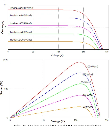
The DC link Converter with Solar PV is shown in Fig. 1. It consists of input power source as Solar PV module, Boost converter, MPPT controller. The specifications Solar PV module used in simulation is 250 Volts, 2000Watts. 250Watts solar panel of maximum voltage and maximum current of 30.3 Volts and 9 Amps respectively with 60 series modules are connected to obtain 2000Watts. The IV and PV characteristics of solar module were obtained for various
irradiance values at constant temperature of 25˚C as shown in Fig. 2.
L
C
PV
Io
`
MPPT +- PI Pulse
Ipv
Vref Cpv
PWM
Fig. 1. Boost Converter with Solar Module
Fig. 2. Solar panel IV and PV characteristics
570
TABLE1
BOOST CONVERTER SPECIFICATIONS
Parameters Values
Input Voltage / Output Voltage 250 V/400 V
Switching Frequency 20 kHz
Duty Cycle 0.38
Boost Inductance (L) 19 mH
Output Capacitance (C) 240 µF
MOSFET – IRF740 400 V, 10 A & 0.48 Ω
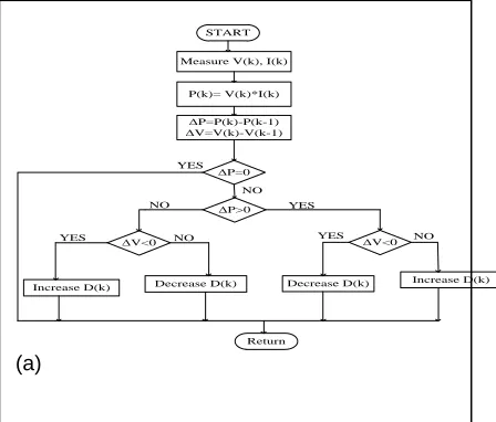
To extract the maximum power from the solar panel, perturb and observe MPPT algorithm is used. The flowchart for P&O algorithm was shown in Fig. 3(a) [7]. In P&O algorithm, at every instant change in power and change in voltage is calculated and estimate correct tracking direction by performing an additional measurement in the middle of the MPPT sampling period. Fig. 3(b) shows PV characteristics drawn with and without MPPT.
3
THREE
PHASE
INVERTER
Fig. 4 shows Grid tied inverter with LCL filter. Inverter is capable for supply both real and reactive power required by the load demand. With help of sinusoidal pulse width modulation (SPWM) techniques, output of inverter will be controlled according to the load requirements [6]. According to the phase angle generated by the reference sine wave, real and reactive power flow can be controlled.Generally, MOSFET Switches are used in inverter circuit having medium power operations. In this design N channel MOSFET IRF840LC is used. The specifications of IRF840LC are VDS=500V, 0.85Ω as input resistance. The output of inverter is not pure sinusoidal and it has THD of 31% so can’t be connected directly into the load. Suitable filter circuit should be design to obtain pure sinusoidal wave with minimum harmonics.
START
YES Measure V(k), I(k)
P(k)= V(k)*I(k)
ΔP=P(k)-P(k-1) ΔV=V(k)-V(k-1)
ΔP=0
ΔP>0
ΔV<0 ΔV<0
Decrease D(k) Decrease D(k) Increase D(k) Increase D(k)
Return YES
NO NO
NO
YES YES NO
(a)
(b)
Fig. 3. (a) Flowchart for MPPT P&O algorithm, (b) MPPT Tracking Curve.
Fig. 4. Three Phase Inverter with LCL Filter
4
LCL
FILTER
DESIGN
To filter out distortion generated in output of VSI, LCL filter with damping resistor is used due to small size and high efficiency of active power transfer and reduce resonance peak. LCL Filter parameters are calculated [9] with modulation index of 0.5, 20% of attenuation factor and 10% of ripple current are listed in Table II.
TABLE2
LCLFILTER SPECIFICATIONS
Grid Frequency 50 Hz
Switching Frequency 20 kHz
Nominal Power 2 kW
Grid Voltage 415 V
DC Link Voltage 400 V
Inverter side inductor 5.11 mH
Grid side inductor 0.21 mH
Filter capacitor 1.86 µF
571
5
MODES
OF
OPERATION
Solar PV based Power transfer will be done in two methods, i) Grid connected mode operation ii) Island mode of operation. When a power produced by the PV Plant is high, Grid connected mode is preferred due to transfer of excess power. Island mode of operation is suitable for power generated by the PV plant is limited quantity that can be accessed by load which is nearer to PV plant.
5.1 Grid Connected Mode of Operation
Grid connected mode is preferred Grid tied model controller is shown in the Fig. 5[10].
abc dq0 abc dq0 PI Vabc Iq + -Id Id´ ++ + Vd abc dq0 Vq Vd SPWM Pulse
PLL Ө
ωL ωL Iq Id PI + -Iq´ + + Vq Iq +
Fig. 5. Grid tied controller.
In grid connected mode, Inverter control tuned as a current controller [8]. Controller will regulate the grid current flow by injecting reactive power. Id and Iq are used to limit the real and reactive currents flows through the grid. PLL is used to make synchronism with grid voltage and current.
5.2 Grid Connected Mode of Operation
In Island mode of operation, inverter control is tuned as voltage controller [11]. Output voltage should be controlled to maintain constant magnitude required by the load even any disturbances occur. Active power transferred to the load should be controlled by limit the current flow done by current limiter. abc dq0 abc dq0 PI Vabc Iabc Vq + + -Vd
Vd´
-+ +
Vd´
abc dq0
Current Limiter
𝑖𝑑2+ 𝑖 𝑑2
Iq
Id Ilim
Vq=0
SPWM Pulse
Ө Ө
Fig. 6.Island mode controller.
6
CONTROLLER
DESIGN
6.1 Current Controller for Grid Connected Mode
In Grid tied mode, Controller senses the grid current at PCC and regulates the grid current making in-phase with grid
voltage by sending the reactive power from solar PV plant. Low pass filter (PI) with feedback mode is used as a regulator.
-+
PI Ginv -+ HLf(s)
Ig_ref(s) Ig(s)
Vg(s)
Fig. 7. Block diagram of closed loop current controller.
The plant transfer function is given by
. The closed loop transfer function is given by
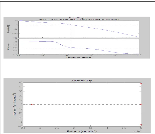
To make controller to operate in stable, optimized
Kp and Ki values to be chosen. By taking 𝑑
, two poles are lie imaginary axis so that system is
marginally stable leads to generate oscillations in output current. From Frequency response, Gain Margin and phase margin is positive so that system is stable.
6.2 Voltage Controller for Island Mode
In island mode, Controller is treated as Voltage control. The plant transfer function is found in terms of load voltage to inverter output voltage. PI controller is used as a compensator. Gain of PWM generator is added in series.
Fig. 8. Bode Plot and Pole Zero plot of closed loop current controller.
-+
PI Kpwm H
Lf(s)
Vg_ref(s) m Ui Vg(s)
Fig. 9.Closed loop Block Diagram of Voltage Controller.
The plant transfer function is given by
. The
572
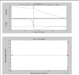
.By seeing the Pole zero plot two poles ate lie
imaginary axis so that system is marginally stable. Gain Margin and phase margin is Positive so that system is
stable by choosing 𝑑 .
7
RESULTS
AND
DISCUSSION
The plant transfer The simulations of grid connected PV System and Islanded mode of operations are simulated in PSIM Software with load of 2000VA at 0.7pf. In grid connected Solar PV mode, solar irradiance of 1000 W/m^2 at 25˚C and 800 W/m^2 at 45˚C are simulated and results are shown in Fig. 11 and Fig. 12. At 1000 W/m^2 at 25˚C Power generated by solar is 2000Watts. Before connecting solar inverter into grid, Grid supplies around 3 amps of current at 0.7pf. inverter comes to 0.98pf.
Fig. 10. Bode Plot and Pole Zero plot of closed loop voltage controller.
operation, grid current falls to 0.56Amps (RMS) with 0.98pf. Inverter supplies around 1340W of real power and 1350VAR of Reactive power. At 800 W/m^2 at 45˚C Power generated by solar is 1500Watts, grid supplies current of 1.1Amps (RMS) with 0.98pf. Inverter supplies around 805W of real power and 1392VAR of Reactive power. In this case real power supplied by inverter gets increases due to decrease in solar power and maintains reactive power supply to grid. In Island mode of operation, solar irradiance of 1000 W/m^2 at 25˚C are simulated and results are shown in Fig. 13. Power generated by solar is 2000Watts. Current supplied to load is 2.95Amps (RMS) with 0.71pf with 1500W of real power and 1500VAR of Reactive power.
8
CONCLUSION
The plant transfer The simulations of grid connected PV System and Islanded mode of operations are simulated in PSIM Software with load of 2000VA at 0.7pf. The design
and analysis of transformer-less solar PV system was designed for grid tied mode of operation and island mode of operation successfully simulated using PSIM simulation tool. Current control techniques can be used for both reactive power compensation techniques and PV power transfer to grid. The overall efficiency of transformerless
Fig. 11. Output waveforms of inverter at 1000 W/ at 25˚C at Grid tied mode.
Fig. 12. Output waveforms of inverter at 800 W/ at 45˚Cat Grid tied mode.
573 Fig. 13. Output waveforms of inverter Island mode
of operation.
REFERENCES
[1] Preethi G, Lavanya D, Sreesureya V,
Boopathimanikandan S, ―Real Time Monitoring and Controlling of Solar Panel Using LabVIEW‖, International Journal of Scientific & Technology Research Volume 8, Issue 08 2019.
[2] Bo Yang Wuhua, Li, Yunjie,Gu, Wenfeng cui,
―Improved Transformerless Inverter with Common mode leakage current Elimination for a photovoltaic grid-connected power system‖, IEEE Transactions On Power Electronics, Vol. 27, no.2 2012.
[3] Jinming Xu, Ting Tang, Shaojun Xie, ―Research on
low-order current harmonics rejections for grid-connected LCL-filtered inverters‖, IET Power Electron., 2014 Vol. 7, 5, 1227–1234 doi:10.1049/iet-pel.2013.0477.
[4] Broeck H V D, Skudelny H and Stanke G, ―Analysis
and realization of a pulse width modulator based on voltage space vectors‖, Conf. Rec. IEEE IAS Annu. Meeting 1986, 244–251.
[5] Mingyu Xue, Yu Zhang, Yong Kang, Yongxian Yi,
Shuming Li and Fangrui Liu, ―Full Feed forward of Grid Voltage for Discrete State Feedback Controlled Grid-Connected Inverter with LCL Filter‖, IEEE Transactions On Power Electronics, Vol. 27, 10 2012.
[6] Tang Y, Loh, P C and Wang P, ―Improved one-cycle-control scheme for three-phase active rectifiers with input inductor-capacitor-inductor filters‖, IET Power Electron.,4, 5, 2011 pp-603–614.
[7] Saurabh Thakran, Jaspreet Singh, Prof. Rachan Garg,
Dr.Priya Mahajan, ―Implementation of P&O Algorithm for MPPT in SPV System‖, International Conference on Power Energy, Environment and Intelligent Control (PEEIC) 2018.
[8] V. H. Prasad, ―Average current mode control of a voltage source inverter connected to the grid: Application to different filter cells,‖ Master’s Thesis,
Dept. Electrical Engineering., Virginia Tech,
Blacksburg, Virginia, 1997.
[9] Reznik, M.Godoy Simões, Ahmed Al-Durra, S. M.
Muyeen, ―LCL Filter Design and Performance Analysis
for Grid Interconnected Systems‖, IEEE Transactions on Industry Applications, Volume 50, Issue 2.
[10] I. Gabe, V. Montagner, and H. Pinheiro, ―Design and implementation of a robust current controller for VSI connected to the grid through an LCL filter‖, Power Electronics, IEEE Transactions on, vol. 24, no. 6, 2009 pp. 1444-1452.