R E S E A R C H
Open Access
Phase reference for the generalized
multichannel Wiener filter
Simon Grimm
1, Toby Christian Lawin-Ore
2, Simon Doclo
2and Jürgen Freudenberger
1*Abstract
The multichannel Wiener filter (MWF) is a well-established noise reduction technique for speech processing. Most commonly, the speech component in a selected reference microphone is estimated. The choice of this reference microphone influences the broadband output signal-to-noise ratio (SNR) as well as the speech distortion. Recently, a generalized formulation for the MWF (G-MWF) was proposed that uses a weighted sum of the individual transfer functions from the speaker to the microphones to form a better speech reference resulting in an improved broadband output SNR. For the MWF, the influence of the phase reference is often neglected, because it has no impact on the narrow-band output SNR. The G-MWF allows an arbitrary choice of the phase reference especially in the context of spatially distributed microphones.
In this work, we demonstrate that the phase reference determines the overall transfer function and hence has an impact on both the speech distortion and the broadband output SNR. We propose two speech references that achieve a better signal-to-reverberation ratio (SRR) and an improvement in the broadband output SNR. Both proposed references are based on the phase of a delay-and-sum beamformer. Hence, the time-difference-of-arrival (TDOA) of the speech source is required to align the signals. The different techniques are compared in terms of SRR and SNR performance.
1 Introduction
Recently, research on speech enhancement using so-called acoustic sensor networks consisting of spatially distributed microphones has gained significant interest [1–12]. Compared with a microphone array at a sin-gle position, spatially distributed microphones are able to acquire more information about the sound field. The usage of spatially distributed microphones allows to employ beamforming techniques for speech quality improvement in reverberant and noisy conditions. Several methods were introduced that use a reference channel. These include the relative transfer function—generalized sidelobe canceler (RTF-GSC) [13], the minimum variance distortionless response (MVDR) beamformer [14], and the speech distortion weighted—multichannel Wiener fil-ter (SDW-MWF) [15, 16].
*Correspondence: [email protected]
This work was supported by the Research Unit FOR 1732 “Individualized Hearing Acoustics” and research grant FR 2673/2-3, both funded by the German Research Foundation (DFG).
1HTWG Konstanz, University of Applied Sciences Institute for System Dynamics—Signal Processing Group, 78462 Konstanz, Germany Full list of author information is available at the end of the article
The MWF is a well-established technique for speech enhancement. It produces a minimum-mean-squared error (MMSE) estimate of an unknown desired signal. The desired signal of the standard MWF (S-MWF) is usually the speech component in one of the microphone signals, referred to as the reference microphone signal. For spatially distributed microphones, the selection of the reference microphone may have a large influence on the performance of the MWF depending on the positions of the speech/noise sources and the microphones [5–7, 17].
With the S-MWF, the overall transfer function from the speakers to the output of the MWF equals the acoustic transfer function (ATF) from the speaker to the reference microphone. Hence, the reference microphone selection determines the amount of speech distortion. Moreover, the overall transfer function has an impact on the broad-band output SNR of the MWF [17]. In [5], an MWF formulation with partial equalization (P-MWF) was pre-sented, where the overall transfer function was chosen as the envelope of the individual ATFs with the phase of an arbitrary reference microphone. This results in a partial
equalization of the acoustic system and an improved broadband output SNR. While this approach has advan-tages with respect to background noise reduction, the reverberation caused by the acoustic environment is not reduced.
Recently, the generalized MWF was proposed in order to improve the broadband output SNR [7] (see also [6]). With the G-MWF, the speech reference is a weighted sum of the speech components, such that the output signal has the same phase as the speech component in the reference microphone. The overall transfer function is the weighted sum of squared amplitudes of all ATFs.
In this work, we consider the phase of the speech reference. That is, we present a further generalization of the G-MWF approach in [7], which enables differ-ent phase references. We demonstrate that the phase of the speech reference shapes the overall transfer function and hence impacts the speech distortion. Moreover, the overall transfer function influences the broadband out-put SNR. We propose two speech references that achieve a better signal-to-reverberation ratio and an improve-ment in broadband output SNR. The proposed references are based on the phase of a delay-and-sum beamformer (DSB) [18].
As shown in [19], the temporal smearing and there-fore the reverberation relies on the all-pass component of the overall transfer function. This suggests that a suit-able phase reference can improve the output SRR of the system. As a consequence, the phase term of a delay-and-sum beamformer is applied as a phase reference of the G-MWF. Similar concepts were proposed in [20–22]. The DSB needs an estimate of the TDOA to align the signals properly. In the literature, several methods for TDOA esti-mation were proposed [23–30]. Many of these techniques are summarized in [29].
The work is a sequel to [21]. In addition to the concept proposed in [21], we present a new approach that com-bines the delay-and-sum beamformer and the P-MWF. Both approaches for the G-MWF can improve the SRR and SNR compared with the S-MWF and P-MWF. Fur-thermore, we present a theoretical analysis of the broad-band output SNR of the G-MWF.
The paper is organized as follows: in Section 2, we introduce the signal model and notation. The G-MWF formulation and the analysis of the output SNR are presented in Sections 3 and 4, respectively. The design of the overall transfer function is explained in Section 5. The block diagram structure of the system is presented in Section 6, together with the necessary TDOA estimation and the challenge of acquiring these estimates in noisy and reverberated environments. In Section 7, the simulation results in terms of SNR and SRR improvement are given, followed by a conclusion in Section 8.
2 Signal model and notation
We consider a linear and time-invariant acoustic system. The beamformer array consists ofMmicrophones. The ith microphone signalyi(k)can be expressed as the convo-lution of the speech signals(k)with the acoustic impulse responsehi(k) from the speech source to theith micro-phone plus an additive noise termni(k). In the short time frequency domain, the resulting microphone signals can be written as follows
Yi(κ,ν)=Hi(ν)S(κ,ν)+Ni(κ,ν). (1)
Yi(κ,ν), S(κ,ν), and Ni(κ,ν) correspond to the short time spectra of the time domain signals. Hi(ν) repre-sents the ATF corresponding to the the acoustic impulse response andXi(κ,ν) = Hi(ν)S(κ,ν)is the speech com-ponent at theith microphone.κandνdenote the subsam-pled time index and the frequency bin index, respectively. In the following, these indices are often omitted when possible. The short time spectra and the ATF can be written asM-dimensional vectors:
X=[X1,X2,. . .,XM]T (2)
N=[N1,N2,. . .,NM]T (3)
H=[H1,H2,. . .,HM]T (4)
Y =[Y1,Y2,. . .,YM]T (5)
Y =X+N (6)
T denotes the transpose of a vector,∗the complex
con-jugate, and†denotes the conjugate transpose. Vectors and matrices are written in bold and scalars are normal letters. We assume that the speech and noise signals are zero-mean random processes with the power spectral densities (PSDs)Ni2andS2. Assuming a single speech source, the speech correlation matrixRShas rank one and there-fore can be expressed as
RS=E
XX†
=PSHH†, (7)
whereEdenotes the mathematical expectation. Similarly,
RN = E
N N†denotes the noise correlation matrix. It is assumed, that the speech and noise terms are uncorre-lated.
The output signalZof the beamformer with filter coef-ficientsG=[G1,G2,. . .,GM]Tis obtained by filtering and summing the microphone signals, i.e.,
Z = G†Y=G†X+G†N
= ZS+ZN (8)
3 Generalized MWF
The MWF aims to estimate an unknown signal H˜dS, where H˜d denotes the overall transfer function of the speech component [15, 16, 31]. The parametric MWF minimizes the weighted sum of the residual noise energy and the speech distortion energy, i.e., the cost function
ξ(G)=E
H˜dS−G†X 2
+μE|G†N|2
, (9)
whereμis a trade-off parameter between noise reduction and speech distortion. The filter minimizing (9) is given by
G=(RS+μRN)−1PSHH˜d∗. (10)
Commonly, the MWF is implemented as
G=(RS+μRN)−1RSu, (11)
whereuis a vector that selects the reference microphone, i.e., the vectorucontains a single one and all other ele-ments are zero. Therefore, the overall transfer function is equal to the ATF of a reference microphone, i.e. Hd = Href.
Since, RS is a rank one matrix, it should be noted that any non-zero vector u achieves the same (opti-mal) narrow-band output SNR. In [7], the generalized MWF was presented, where the elementsui of the vec-torudefine a speech reference for the MWF which is a weighted sum of the speech components in the different microphones with the phase of the speech component in the reference microphone signal. The vectorucan be used to define the desired complex-valued response as
˜
Hd=u†H= i
u∗i ·Hi for ui ∈C. (12)
In [7], the magnitude of the responseH˜dwas designed to improve the broadband output SNR, whereas the phase term of H˜d was set equal to the phase of the ATF in the reference microphone. In contrast to the approach in [7], we consider a complex-valued selection vectoru
which enables different phase references. In the following, we demonstrate thatH˜dcan be considered as the overall transfer function.
3.1 MWF overall transfer function
According to [5] and many others, the MWF in (10) can be decomposed using the matrix inversion lemma as
G = PS
PS+μ(H†R−N1H)−1
R−N1H H†R−N1HH˜
∗
d (13)
= GWFGMVDRH˜d∗, (14) i.e., a MVDR beamformer
GMVDR=
R−N1H
H†R−N1H, (15)
a filterH˜d, and a single-channel Wiener post filter
GWF=
PS
PS+μ(H†R−N1H)−1
. (16)
Without noise reduction, i.e., for μ = 0, the overall transfer function equalsH˜d, becauseGMVDR has a unity gain transfer function. The output signal can be written as
ZS= ˜Hd·S. (17)
In the following, we consider some special cases of the MWF. Note that the different formulations of the G-MWF differ only with respect to the vector u and the corresponding transfer functionH˜d.
3.2 MVDR beamformer
The MVDR beamformer obtains perfect equalization of the acoustic system, where the overall transfer function is chosen to beH˜d=1. Hence, the elements of the vectoru are
ui= Hi
H†H. (18)
However, the resulting G-MWF requires perfect knowl-edge about the ATF from the speaker to the microphones. The corresponding issue of blind channel estimation is a challenging task in noisy environments and so far an unsolved problem. A further issue is the inversion of the squared norm of the ATFs, since they may contain zeros in their magnitude response.
3.3 Selection of a reference channel
In the S-MWF, the overall transfer functionH˜dis equal to the ATF from the speaker to one of the microphones, i.e.,
˜
Hd = Hrefwhere ref denotes the index of the reference microphone. In this case, the numerator of the S-MWF can be written as
RSu=PSHH†u=PSHH˜ref∗ , (19)
whereuis a column vector of lengthMthat selects the ref-erence microphone, i.e., the corresponding entry is equal to one, while all other entries are equal to zero. As a result, the corresponding ATF remains as the overall transfer function.
Compared to the MVDR beamformer in Section 3.2, the advantage of the S-MWF is that it only depends on esti-mates of the signal statistics, i.e.,RSandRNand no explicit knowledge of the ATFs is required. However, it should be noted that the output signal is as reverberant as the input signal.
3.4 Partial equalization approach
envelope of the individual ATFs, and the phase is chosen as the phaseφrefof an arbitrary (reference) ATF, i.e.,
˜ Hd=
H†Hejφref. (20)
This formulation results in a partial equalization of the acoustic system, since the dips in the magnitude response of the individual ATFs can be avoided. The elements of the vectorucan be computed as
ui= for the P-MWF, we have
RSu=RS
Similar to the S-MWF, the P-MWF only depends on the signal statistics and therefore no explicit knowledge of the ATFs is required. It should be noted that the phase of the output speech component is equal to the phase of the reverberant speech component in the reference micro-phone signal. As a result, the P-MWF approach equalizes the amplitude of the desired overall transfer function, but the output signal is as reverberant as the selected microphone signal.
4 Output SNR
In this section, we investigate the narrow-band and broad-band output SNR of the different MWF formulations. Firstly, we consider the narrow-band output SNR
γ (ν)= E
Using Eq. (14), we have
γ (ν) =
Consequently, the narrow-band output SNR is inde-pendent of the particular choice ofH˜d. Nevertheless,H˜d impacts the broadband output SNR, which is defined as
γout =
Note that the PSD of the speech component at the out-put of the MVDR beamformer isPS. Hence, the PSD of
the speech componentZSat the output of the G-MWF is E|ZS(ν)|2 = |GWF|2| ˜Hd|2PS. Similarly, the PSD of the noise component at the output of the MVDR beam-former is PN,MVDR = G†MVDRRNGMVDR, such that the PSD of the noise component at the output of the G-MWF isE|ZN(ν)|2
From this equation, it can be seen that the overall trans-fer function as well as the single-channel Wiener post filter impact the broadband output SNR.
Next, we consider the responseH˜d that maximizes the broadband output SNR. Equation (26) can be written as
γout =
where F denotes the total number of frequency bins. Maximizingγout is equivalent to solving the generalized eigenvalue problemAH˜ = λBH˜ orB−1AH˜ = λH˜. The solution to the eigenvalue problem is the eigenvector cor-responding to the largest eigenvalueλmax. SinceB−1Ais a diagonal matrix, the largest eigenvalue is
λmax=maxν αν βν =maxν
PS(ν) PN,MVDR(ν)
. (28)
Comparing Eqs. (28) with (26), we obtain the corre-sponding eigenvectorH˜ =[ 0,. . ., 1,. . ., 0]T, with a one in the frequency bin corresponding to the largest eigenvalue and zero elsewhere. Although this overall transfer func-tion maximizes the broadband output SNR, the corre-sponding speech distortion will not be acceptable, because only one frequency bin will pass the beamformer.
5 MWF reference selection
It was shown in [19] that the temporal smearing and there-fore the reverberation relies on the all-pass component of the overall ATF. This suggests that a suitable phase ref-erence can improve the output SRR. In this section, we present two formulations of the G-MWF that improve the SRR and the broadband output SNR compared with the S-MWF or the P-MWF. Both formulations use a phase ref-erence from a DSB, which delays the microphone signals to compensate for the different times of arrival. Hence, the DSB enhances the direct path component and, as we will see in Section 7, improves the SRR.
5.1 Delay-and-sum beamformer
In the first approach, we propose to simply use the out-put of a delay-and-sum beamformer as the speech refer-ence. The corresponding elements of the vectorucan be described as
ui= 1 M·e
j2πFντiforν∈0,. . .,F−1, (29)
where τi is a delay (in samples), which compensates the TDOA of the direct path speech components at the microphones. The speech components are typically aligned to the microphone with the latest arrival time to obtain a causal DSB. Using (12) we obtain the overall transfer function
˜ Hd=
1 M
i
Hie−j2π
ν
Fτi. (30)
5.2 Partial equalization with DSB phase reference
The second approach is a combination of the P-MWF with the DSB as the phase reference. As already described in Section 3.4, the phase reference of the P-MWF is the phase of an arbitrary ATF. In order to improve the SRR, we can
use the DSB as the phase reference. The resulting vectoru
can be described as
ui=
rSi,i tr(RS)·e
j2πνFτi for ν∈0,. . .,F−1. (31)
Note that the phase term impacts the magnitude of the overall transfer functionH˜d, cf. (12). Comparing (21) and (31), we haveui= √|Hi|
H†He
j2πνFτiand
˜ Hd=
1
√
H†H i |Hi|Hie
−j2πν
Fτi. (32)
Hence, the direct path speech components in the micro-phones are aligned, but additionally the microphone sig-nals are weighted with the magnitude of the ATFs similar to the P-MWF approach.
6 System structure of the G-MWF
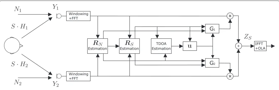
Figure 1 depicts the block diagram of the G-MWF for an array with two microphones. Since the filtering is performed in the frequency domain, the microphone sig-nals are first windowed and then transformed using the fast Fourier transform (FFT).
A frequency-dependent voice activity detector (VAD) as proposed in [32] is used to estimate the required correla-tion matrices for the G-MWF. During speech pauses and in frequency bins where no speech activity is detected, the estimate of the noise correlation matrix RN is updated. The estimate of the speech correlation matrix RS is obtained from the input correlation matrixRYas
RS=RY−RN. (33)
Furthermore, for the phase reference proposed in Section 5, the TDOA from the speaker to the micro-phones is required, to achieve a coherent summation of the microphone signals. Depending on the TDOA, a suitable vector u is derived to compensate the phase differences of the microphone signals, as calculated in Eq. (29). A very popular TDOA estimation approach
is the generalized cross correlation (GCC) method [23, 28, 29], where the cross-correlation between the microphone signals is calculated in the frequency domain as the cross power spectral density (CPSD). Depending on the application and the environmental conditions, the CPSD is typically weighted with a coherence or noise-based weighting using the magnitude spectrum of the CPSD. The weighted CPSD is transformed to the time domain using the inverse Fourier transform, resulting in the cross correlation vector. The main peak in the cross correlation vector indicates the time delay. It should be noted that the TDOA estimate is only valid in signal blocks where the speaker is active, which can be deter-mined based on a VAD.
It should be noted that the phase of the CPSD is equal to the phase of the relative transfer function (RTF) between the microphones, since both only differ from a different magnitude response. Since in general the microphone sig-nals contain correlated noise components, estimating the RTFs directly from the noisy microphone signals leads to biased RTF estimates. Several methods for unbiased RTF estimation have been proposed, e.g., by exploiting the non-stationarity of speech signals [13, 33] or based on the generalized eigenvalue decomposition ofRY andRN [34, 35]. In [36], an approach for unbiased RTF estima-tion was proposed, requiring estimates of the PSDs and CPSDs of the speech and noise components, which can be obtained from the estimated speech and noise corre-lation matrices RS andRN. The RTF estimate between microphonesiandjis computed as a combination of two weighted coefficients
where the termsfiandfjare SNR-based weighting coeffi-cients which are defined as
fi =
We propose a slightly modified approach based on frequency-dependent VAD [32], where the RTF estimate is updated only in frequency bins where speech activity is detected. Furthermore, a smoothing parameter to average the RTF estimate is used, which is the rate of all frequency bins where speech activity is detected. By applying the inverse Fourier transform, Wˆunbiasedcan be transformed back into the time domain, which results in the vector
ˆ
wunbiased. The location of the peak value that indicates the delay to the microphonejcan be calculated as
τi=arg max
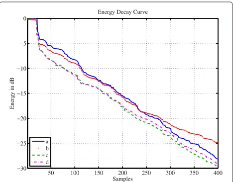
To verify the SRR and SNR improvements provided by the proposed approaches, different simulations were carried out. In the following, G-MWF-1 denotes the G-MWF that uses the DSB as the speech reference, i.e., (29), whereas G-MWF-2 denotes the partial equalization approach, using the DSB only as a phase reference, i.e., (31). For the S-MWF and the P-S-MWF, the first microphone was used as the reference. All simulations were performed with a sampling rate of 16 kHz and an FFT length F = 512. We consider a noisy car environment as well as a rever-berant classroom. The signals for testing the algorithms are ITU speech signals convolved with measured impulse responses. For the car scenario, this was done with an artificial head and two cardioid microphones that were mounted close to the rear-view mirror. For the class-room scenario [37] impulse responses were recorded with a loudspeaker and omnidirectional microphones at two different spatial locations with a microphone distance of 0.5 m. The reverberation timeRT60of the classroom has a value between 1.5 and 1.8 s over all frequencies. To evalu-ate the dereverberation capabilities of the algorithms, the energy decay curves (EDCs) [38] of the resulting over-all transfer functions H˜d using the measured impulse responses were calculated (forμ = 0). For the car envi-ronment, the resulting EDCs are shown in Fig. 2.
50 100 150 200 250 300 350 400
Curve (a) depicts the EDC of the overall transfer func-tion for the S-MWF. Curve (b) depicts the resulting EDC of the overall transfer function of the P-MWF. Com-pared with (a), it can be observed that the decay time is increased, but the energy of the first reflections is reduced due to the partial equalization as can be seen from the first 230 samples of the EDC. Curves (c) and (d) depict the EDC of the overall transfer function for the G-MWF-1 and G-MWF-2, respectively. Compared with (a) and (b), a reduced decay time is observed due to the coher-ent combining of the phase terms. As a result, the direct components of the ATF are enhanced, which leads to an improvement in speech quality of the overall system.
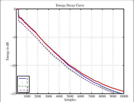
For the classroom scenario, the resulting EDCs are shown in Fig. 3. Due to the longer reverberation time, compared with the car environment, the resulting EDCs show a different behavior. Curves (e) and (f ) depict the EDCs of the resulting transfer function for the S-MWF and the P-MWF, respectively. Curves (g) and (h) depict the EDCs of the overall transfer functions for the G-MWF-1 and the G-MWF-2. Compared to (e), it can be observed in (f ) that the direct signal component for the first few sam-ples is augmented, due to the partial equalization, but that the decay time is increased. While (h) still shows a slightly better performance than (g) for the first 7000 samples, the decay time is increased by a small amount compared with (h) during the samples 7000–10,000. However, the reverberation energy for the G-MWF-1 and G-MWF-2 in (g) and (h) is noticeably reduced compared with (e) and (f ).
As a measure of reverberation, the direct-to-reverberation ratio (DRR) can be calculated from the
1000 2000 3000 4000 5000 6000 7000 8000 9000 10000 −15
Fig. 3EDC of the resulting acoustic transfer functions of the classroom environment: (e) ATF from the speech signal source to microphone 1 (S-MWF), (f) overall transfer function of P-MWF with phase reference of microphone 1, (g) overall transfer function of G-MWF-1, (h) overall transfer function of G-MWF-2
resulting overall transfer functions H˜d. The DRR is defined as [39]
wherehd is the impulse response of the overall transfer functionH˜din the time domain andndare the samples of the direct path. Fornd, we considered a time interval of 8 ms after the first arrival of the direct sound. In Table 1, the DRR values for the different overall transfer functions
˜
Hdare presented. From the table, it can be seen that the G-MWF approaches improve the DRR in both scenarios compared with the S-MWF and P-MWF.
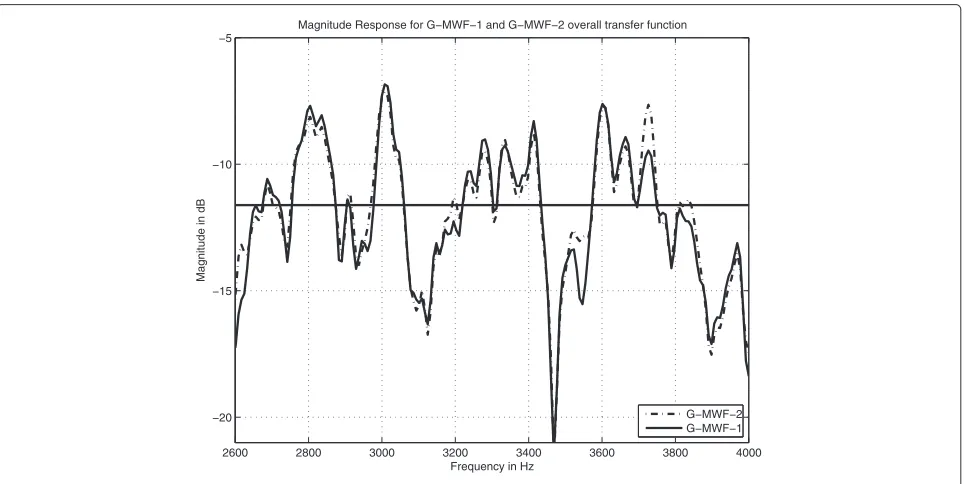
Both versions of the G-MWF result in similar overall transfer functions. This can be observed in Figs. 4 and 5. Figure 4 presents the magnitude response of the ATFs of the car environment for both microphones as well as the overall transfer function of G-MWF-2 for frequencies between 2600 and 4000 Hz. Clearly, the resulting par-tial equalization of the G-MWF-2 can be seen. Figure 5 depicts the overall transfer function of both G-MWF ver-sions for the same frequency section. It is shown that the magnitude response of both approaches looks quite similar.
Finally, we consider a noisy car scenario. The noise was recorded at a driving speed of 100 km/h with the same microphone setup as specified above. For μ > 0, the MWF performs an adaptive noise reduction and there-fore the resulting overall transfer function is time varying. As a result, signal-based performance measures for the noise reduction and dereverberation performance need to be used. For the dereverberation performance, the signal-to-reverberation ratio (SRR) after [39] is used, i.e.,
SRR=10 log10
wheresd(k)is the direct path signal component of the first microphone and ˆs(k) is the output signal of the beam-former in the time domain. It should be noted that this measure is only valid for signal segments, where speech activity is detected.
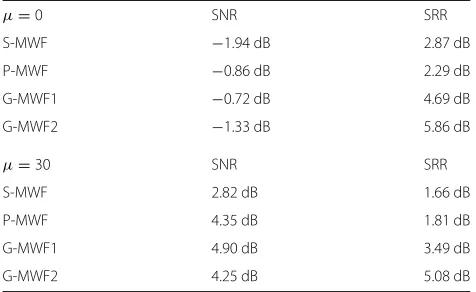
Table 2 presents the results for the SRR and the broad-band output SNR for two settings of the trade-off param-eterμ, where a larger value of μ results in more noise
Table 1DRR of the overall transfer function for choosing a different phase and magnitude reference
S-MWF P-MWF G-MWF1 G-MWF2
Car scenario 12.6 dB 9.3 dB 14.7 dB 14.3 dB
2600 2800 3000 3200 3400 3600 3800 4000 −40
−35 −30 −25 −20 −15 −10 −5 0
Magnitude Response of G−MWF−2 overall transfer function
Magnitude in dB
Frequency in Hz
ATF1 ATF2 G−MWF−2
Fig. 4Magnitude response of G-MWF2
reduction. The SRR was measured in time frames where speech was present. The performance of both G-MWF approaches are compared with the S-MWF and P-MWF. It can be observed that both G-MWF approaches outper-form the S-MWF in terms of SRR and SNR. G-MWF-1 outperforms the P-MWF in terms of SRR and SNR, whereas MWF-2 improves the SRR compared to G-MWF-1 at the expense of a small SNR loss.
8 Conclusions
For the multichannel Wiener filter, the influence of the phase reference is often neglected, because it has no impact on the narrow-band output SNR. In this work, we have shown that the phase reference influences the overall transfer function. Moreover, the overall transfer function determines the speech distortion and impacts the broad-band output SNR. We have proposed two generalized
2600 2800 3000 3200 3400 3600 3800 4000 −20
−15 −10 −5
Magnitude Response for G−MWF−1 and G−MWF−2 overall transfer function
Magnitude in dB
Frequency in Hz
G−MWF−2 G−MWF−1
Table 2SRR and SNR comparison for different MWF formulations
G-MWF1 4.90 dB 3.49 dB
G-MWF2 4.25 dB 5.08 dB
formulations for the MWF where the phase reference is based on the phase of a delay-and-sum beamformer. The proposed G-MWF technique requires an estimate of the time-difference-of-arrival, which can be acquired from the estimates of the speech and noise correlation matri-ces. Thus, the G-MWF requires only information about the second order statistics of the signals. The presented simulation results indicate that both G-MWF versions can achieve a better signal-to-reverberation ratio and an improvement in broadband output SNR compared to pre-viously known MWF formulations.
Competing interests
The authors declare that they have no competing interest.
Author details
1HTWG Konstanz, University of Applied Sciences Institute for System
Dynamics—Signal Processing Group, 78462 Konstanz, Germany.2University of
Oldenburg Dept. of Medical Physics and Acoustics and Cluster of Excellence Hearing4All, 26111 Oldenburg, Germany.
Received: 16 December 2015 Accepted: 20 June 2016
References
1. S Wehr, I Kozintsev, R Lienhart, W Kellermann, inProceedings of IEEE Sixth International Symposium on Multimedia Software Engineering.
Synchronization of acoustic sensors for distributed ad-hoc audio networks and its use for blind source separation (IEEE, 2004), pp. 18–25 2. S Doclo, M Moonen, T Van den Bogaert, J Wouters, Reduced-bandwidth
and distributed MWF-based noise reduction algorithms for binaural hearing aids. IEEE Transac. Audio, Speech, and Language Processing. 17(1), 38–51 (2009)
3. TC Lawin-Ore, S Doclo, inIEEE International Conference on Acoustics, Speech and Signal Processing (ICASSP). Analysis of rate constraints for MWF-based noise reduction in acoustic sensor networks (IEEE, 2011), pp. 269–272 4. S Stenzel, J Freudenberger. Blind matched filtering for speech
enhancement with distributed microphones, vol. 2012, (2012), p. 15. Article ID 169853
5. S Stenzel, TC Lawin-Ore, J Freudenberger, S Doclo, inIEEE Workshop on Applications of Signal Processing to Audio and Acoustics. A multichannel Wiener filter with partial equalization for distributed microphones, (Mohonk Mountain House, New Paltz, NY, 2013)
6. TC Lawin-Ore, S Stenzel, J Freudenberger, S Doclo, inProceedings of the International Workshop on Acoustic Signal Enhancement (IWAENC). Alternative formulation and robustness analysis of the multichannel
Wiener filter for spatially distributed microphones, (Antibes, France, 2014), pp. 208–212
7. TC Lawin-Ore, S Stenzel, J Freudenberger, S Doclo, inProc. ITG Conference on Speech Communication. Generalized multichannel Wiener filter for spatially distributed microphones, (Erlangen, Germany, 2014), pp. 1–4 8. TC Lawin-Ore, S Doclo, Analysis of the average performance of the
multichannel Wiener filter based noise reduction using statistical room acoustics. Signal Process.107, 96–108 (2015)
9. S Markovich-Golan, A Bertrand, M Moonen, S Gannot, Optimal distributed minimum-variance beamforming approaches for speech enhancement in wireless acoustic sensor networks. Signal Process.107, 4–20 (2015) 10. J Schmalenstroeer, P Jebramcik, R Haeb-Umbach, A combined
hardware-software approach for acoustic sensor network synchronization. Signal Process.107, 171–184 (2015)
11. S Miyabe, N Ono, S Makino, Blind compensation of interchannel sampling frequency mismatch for ad hoc microphone array based on maximum likelihood estimation. Signal Process.107, 185–196 (2015)
12. L Wang, S Doclo, Blind compensation of interchannel sampling frequency mismatch for ad hoc microphone array based on maximum likelihood estimation. IEEE/ACM Trans. Audio, Speech Lang. Process.24, 571–582 (2016)
13. S Gannot, D Burshtein, E Weinstein, Signal enhancement using beamforming and nonstationarity with applications to speech. IEEE Transac. Signal Process.49(8), 1614–1626 (2001)
14. EAP Habets, J Benesty, I Cohen, S Gannot, J Dmochowski, New insights into the MVDR beamformer in room acoustics. IEEE Transactions on Audio, Speech, Language Process.18(1), 158–170 (2010) 15. J Chen, J Benesty, Y Huang, S Doclo, New insights into the noise
reduction Wiener filter. IEEE Transac. Audio, Speech Lang. Process. 14(4), 1218–1234 (2006)
16. S Doclo, A Spriet, J Wouters, M Moonen, Frequency-domain criterion for the speech distortion weighted multichannel Wiener filter for robust noise reduction. Speech Commun.49(7–8), 636–656 (2007) 17. TC Lawin-Ore, S Doclo, inProceedings of 10. ITG Symposium on Speech
Communication. Reference microphone selection for MWF-based noise reduction using distributed microphone arrays (VDE, Braunschweig, 2012), pp. 31–34
18. JB Allen, DA Berlkey, J Blauert, Multimicrophone signal-processing technique to remove room reverberation from speech signals. J. Acoust. Soc. Am.62(4), 912–915 (1977)
19. Q-G Liu, B Champagne, P Kaba, Room speech dereverberation via minimum-phase and all-pass component processing of
multi-microphone signals. IEEE Pacific Rim Conf. Commun. Comput. Signal Process, 571–574 (1995)
20. EAP Benesty, J Habets, A two-stage beamforming approach for noise reduction and dereverberation. IEEE Transac. Audio, Speech, Language Process.21(5), 945–958 (2013)
21. S Grimm, J Freudenberger, inJahrestagung für Akustik (DEGA). A phase reference for a multichannel Wiener filter by a delay and sum beamformer, (Nürnberg, 2015), pp. 208–212
22. I Kodrasi, S Doclo, Joint dereverberation and noise reduction based on acoustic multichannel equalization. IEEE Transac. Audio, Speech, Lang. Process.24(4), 680–9693 (2016)
23. C Knapp, G Carter, The generalized correlation method for estimation of time delay. IEEE Transac. Acoust. Speech Signal Process.24(4), 320–327 (1976)
24. GC Carter,Coherence and time delay estimation: an applied tutorial for research, development, test and evaluation engineers. (IEEE Press, 1993) 25. S Doclo, M Noonen, Robust adaptive time delay estimation for speaker
localization in noisy and reverberant acoustic environments. EURASIP J. Appl Signal Process.11, 1110–1124 (2003)
26. MS Brandstein, HF Silverman, A robust method for speech signal time-delay estimation in reverberant rooms. Proc. IEEE Int. Conf. Acoust. Speech Signal Process.1, 375–378 (1997)
27. TG Dvorkind, S Gannot, Time difference of arrival estimation of speech source in a noisy and reverberant environment. Signal Process.85(1), 177–204 (2005)
29. J Chen, J Benesty, Y Huang, Time delay estimation in room acoustic environments: an overview. EURASIP J. Appl. Signal Process.2006, 1–19 (2006)
30. TG Manickam, RJ Vaccaro, DW Tufts, A least-squares algorithm for multipath time-delay estimation. IEEE Transac. Signal Process.42(11), 3229–3233 (1994)
31. S Doclo, A Spriet, M Moonen, J Wouters, inSpeech Enhancement. Speech distortion weighted multichannel Wiener filtering techniques for noise reduction, chapter 9 (Springer, Berlin/Heidelberg, 2005)
32. J Freudenberger, S Stenzel, inIEEE Workshop on Statistical Sig. Proc. (SSP), Nice. Time-frequency dependent voice activity detection based on a simple threshold test (IEEE, Nice, 2011)
33. I Cohen, Relative transfer function identification using speech signals. Speech Audio Process. IEEE Transac.12(5), 451–459 (2004) 34. S Markovich-Golan, S Gannot, I Cohen, Multichannel eigenspace
beamforming in a reverberant noisy environment with multiple interfering speech signals. IEEE Transac. Audio, Speech, Lang. Process. 17(6), 1071–1086 (2009)
35. S Markovich-Golan, S Gannot, inIEEE International Conference on Acoustics, Speech and Signal Processing (ICASSP). Performance analysis of the covariance subtraction method for relative transfer function estimation and comparison to the covariance whitening method (IEEE, South Brisbane, 2015), pp. 544–548
36. M Schwab, P Noll, T Sikora, inEuropean Signal Processing Conference (EUSIPCO). Noise robust relative transfer function estimation, vol. 2 (IEEE, Florence, 2006), pp. 1–5
37. R Stewart, M Sandler, inIEEE International Conference on Acoustics Speech and Signal Processing (ICASSP). Database of omnidirectional and B-format room impulse responses (IEEE, Dallas, 2010), pp. 165–168
38. MR Schroeder, Frequency correlation functions of frequency responses in rooms. J. Acoust. Soc. Am.34(2), 1819–1823 (1962)
39. PA Naylor, ND Gaubitch,Speech Dereverberation, 1st edn. (Springer, London, 2010)
Submit your manuscript to a
journal and benefi t from:
7Convenient online submission
7Rigorous peer review
7Immediate publication on acceptance
7Open access: articles freely available online
7High visibility within the fi eld
7Retaining the copyright to your article