R E S E A R C H
Open Access
Performance analysis of joint relay selection
and transmission schemes in multiple-antenna
two-way relay systems
Chen Chen
1*, Xingbin Wang
2, Yehua Yang
1and Ye Jin
1Abstract
In this paper, we consider a two-way relay system with two multi-antenna sources and multiple single-antenna relays and study the performances for various transmission schemes with the assumption that perfect channel state
information (CSI) is available at both the sources and the relays. Although a transmission scheme that combines source beamforming and relay selection (BF-RS) is known to improve a system performance, its performance has not been theoretically analyzed yet. In the paper, we focus on the performance analysis in terms of the symbol error probability (SEP) for the BF-RS scheme. The analytical upper and lower bounds of the end-to-end system SEP are derived in the closed form, and the asymptotic SEP expression is given in high SNR regime. By both analytical and simulation results, it is clearly shown that a full transmit and relay selection diversity gain can be achieved without code rate loss. The SEP curves from simulations show that our derived bounds can predict the performance accurately. Based on the derived analytical results, we propose an individual power allocation (IPA) scheme to save the total transmit power. We show that the IPA scheme can result in considerable energy saving with a comparable SEP performance.
Keywords: Two-way relay system; Physical-layer networking coding; Diversity gain; Power allocation
1 Introduction
In order to achieve a higher throughput and spectral effi-ciency, protocols consisting of the multiple access (MAC) and broadcast (BC) phases in a two-way relay channel (TWRC) have attracted more research interests than con-ventional protocols using three or four phases. Since the physical-layer network coding (PNC) protocol can be eas-ily applied to two-way relay systems, its performance has been widely studied [1].
For reliable transmissions, it is important to exploit diversity gain in multi-input multi-output (MIMO) wire-less communications. Relay selection (RS) diversity can also be exploited in MIMO TWRC in conjunction with transmit diversity. For instance, To et al. [2] considered a two-way relay system using the Alamouti’s code at the two sources while there is only one antenna at a relay.
*Correspondence: [email protected]
1State Key Laboratory of Advanced Optical Communication Systems and Networks, Peking University, 100871 Beijing, China
Full list of author information is available at the end of the article
Gong et al. [3] studied a system consisting of two single-antenna sources and a single relay of two-single-antenna. Relay and antenna selection schemes are also addressed in many related works in MIMO TWRC. Chen et al. [4] proposed a RS and beamforming scheme for cooperative two-way relay systems with the amplify-and-forward (AF) proto-col. Jia et al. [5] investigated the outage probability and ergodic capacity of the two-way network coding oppor-tunistic relaying systems with the AF protocol. Jayasinghe et al. [6] proposed a robust joint precoder-decoder design scheme for a multiple-input multiple-output PNC-based two-way relay system.
Zhou et al. [7] proposed an opportunistic two-way relay scheme based on joint network coding and opportunistic relaying with the decode-and-forward (DF) protocol. The analysis and design of space-time trellis codes (STTCs) for TWRC with multi-antenna sources and single-antenna relays were studied with the AF protocol [8].
Although various approaches for efficient transmission schemes with RS are proposed, it is interesting to note that joint transmission and RS schemes for MIMO TWRC are not well studied. In other words, the individual analysis
of either the transmission schemes or the RS schemes has been well investigated, but a best combination of the transmission and RS schemes under a certain perfor-mance criterion is not known, especially in asymmetrical multi-antenna two-way relay systems. In addition, it is proved that an opportunistic RS scheme with low com-plexity can achieve better performance than a fully dis-tributed two-way relay scheme [7] and it is shown that the DF protocol outperforms the AF protocol in terms of symbol error probability (SEP) performance [9]. With the demand of reliable transmissions, combining the best known techniques in multiple-antenna two-way relay sys-tems would lead us to the best joint scheme; however, its performance is not known yet.
In addition, it is well known that the power allocation (PA) plays an important role in wireless communications. With a total power constraint, the PA is widely used to improve the system performance. With individual power constraints, the PA can be used to save the system power consumption. Song et al. [10] proposed a PA scheme based on the asymptotic SEP in AF two-way relay systems. Zhang et al. [11] proposed a PA scheme to minimize the maximum individual outage probability. Talwar et al. [12] presented an optimal joint RS and PA scheme to max-imize the worst received signal-to-noise ratio (SNR) in AF two-way relay systems. Do et al. [9] proposed a joint relay selection and PA scheme to improve the SEP perfor-mance in a two-way relay system with the DF protocol. To the best of our knowledge, all these works are based on the total transmission power constraint. However, the relays and the sources could be battery-powered, which means that individual transmission power constraints at nodes are more suitable for two-way relay systems with battery-powered nodes. Hence, under individual trans-mission power constraints, it would be needed to consider an individual power allocation (IPA) scheme to improve the system power efficiency in a multiple-antenna two-way relay system.
In this paper, as mentioned earlier, the combination of the best known techniques for a multiple-antenna two-way relay system consisting of two sources of multiple antennas and multiple relays of single antenna is consid-ered. A transmission scheme that combines beamform-ing and RS (BF-RS) is mainly considered. We present an asymptotic SEP expression for the proposed BF-RS scheme and make comparison with other transmission schemes. Through analysis and simulation results, it can be shown that a full transmit and RS diversity gain can be achieved by the BF-RS scheme. Thus, we can confirm that the BF-RS scheme is optimal in terms of the diversity gain. Furthermore, we consider a general case where two sources are equipped with M and N antennas and K
relays participate in the transmission to derive closed-form expressions for tight upper and lower bounds on SEP.
In order to improve the system power efficiency, an IPA scheme is also proposed to reduce the total transmission power cost. The performance of the BF-RS scheme and the IPA scheme is verified through simulations.
The main contributions of this paper are summarized as follows. (i) Despite that the BF-RS scheme is based on existing approaches, its performance has not been well investigated in a theoretical manner. We derive the upper and lower bounds of the end-to-end system SEP in an asymmetrical multi-antenna two-way relay system, where the source nodes are equipped with different numbers of antennas. The derived SEP expressions are tight and are verified with the simulated results. (ii) We conduct the asymptotic SEP performance analysis and evaluate the diversity order. We demonstrate that the BF-RS scheme can achieve a full transmit and RS diversity gain and out-performs other transmission and RS schemes. (iii) Under individual transmission power constraints, we propose an IPA scheme to improve the system power efficiency. The behaviors of the system power efficiency under different system configurations are investigated. Meanwhile, both simulated and analytical results show that the proposed IPA scheme can yield considerable energy saving with a comparable SEP performance to other PA schemes.
The rest of this paper is organized as follows. In Section 2, a system model of a multiple-antenna two-way relay system is introduced. In Section 3, we investigate the optimal beamforming and the RS criteria. In Section 4, an asymptotic SEP expression and the closed-form bounds are discussed. In Section 5, the IPA scheme for the BF-RS is given. Simulation results are shown to corroborate our theoretical results in Section 6. In Section 7, we draw the main conclusion.
The following notations are used in this paper. Lower and upper boldfaced letters are used for column vec-tors and matrices. (·)∗ and(·)T represent the conjugate and transpose, respectively. For a vector or matrix, · denotes the Frobenius norm.CN(μ,σ2)denotes the cir-cularly symmetric complex Gaussian distribution with meanμand varianceσ2. For a random variable (RV)X,
E[f(X)] represents the expectation of a function of X,
f(X).fX(·), andFX(·)refer to the probability density
func-tion (PDF), and the cumulative density funcfunc-tion (CDF) of
X, respectively.
2 System model
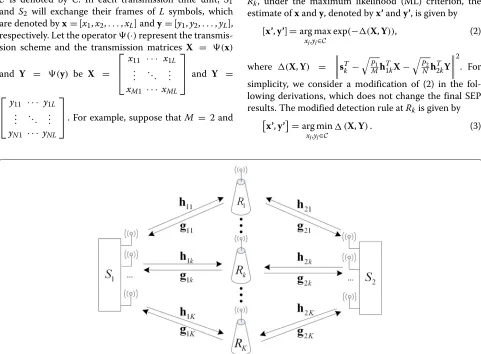
In this paper, we consider a multiple-antenna two-way relay system where two multi-antenna source nodes,S1 andS2, are equipped withMandNantennas, respectively, andK relay nodes,{R1,. . .,RK}are equipped with single
antenna.S1andS2exchange their information with the help of one selected relay, sayRk. This system model can
a selective single antenna relay, which is due to the size and complexity constraints. We assume that the channel state information (CSI) remains unchanged during a transmis-sion time unit consisting of two phases (the first is the MAC phase and the second is the BC phase). The detailed system model is shown in Fig. 1.
In the MAC phase, the relays can receive signals from
S1andS2. Based on the perfect CSI assumption, the best relay Rk out ofK relays is selected (the RS criteria will
be discussed later). Then, the selected relay forwards the detected signals to bothS1andS2in the BC phase. Using the PNC protocol,S1andS2can detect the desired infor-mation from each other. We assume that all the sources and relays operate in time division duplex mode, and per-fect synchronization has been established between the sources and the relays before data transmission. In this section, we will consider a generic representation for vari-ous transmission schemes that can achieve a full transmit diversity such as beamforming, space time block coding (STBC), and so on.
We assume that the same signal constellationCis used at sources and relays throughout the paper. The size of C is denoted by C. In each transmission time unit, S1 and S2 will exchange their frames of L symbols, which are denoted byx=[x1,x2,. . .,xL] andy=[y1,y2,. . .,yL],
respectively. Let the operator(·)represent the transmis-sion scheme and the transmistransmis-sion matrices X = (x)
and Y = (y) be X =
⎡ ⎢ ⎣
x11 · · · x1L
..
. . .. ...
xM1 · · · xML
⎤ ⎥
⎦ and Y =
⎡ ⎢ ⎣
y11 · · · y1L
..
. . .. ...
yN1 · · · yNL ⎤ ⎥
⎦. For example, suppose thatM = 2 and
L=2. Then, we can show that each transmission scheme has a different form of(x). For the Alamouti code [13],
we haveX=(x)asX=
x1 −x2∗
x2 x1∗ . For the diagonal
code ([14], 6.2.22), we haveX= (x)asX=
x1 0
0 x1 . For the beamforming scheme in ([14], 6.1.12), we have
X=(x)asX=
w1x1 w1x2
w2x1 w2x2 , wherewi,i=1, 2 are the beamforming weights. WithXandY, the received signal atRk(k=1, 2,. . .,K)in the MAC phase can be expressed as
sTk =
P1
Mh
T
1kX+
P2
Nh
T
2kY+Tk,k=1, 2,. . .,K,
(1)
where h1k =
h11,kh12,k . . . h1M,kT and h2k =
[h21,k h22,k . . . h2N,k]T are the channel vectors between
relayRk andS1and relay Rk andS2, respectively. k ∼ CN0,σ2IL
is the background noise vector atRk.Pmis
the transmit power ofSm,m=1, 2.
Since the CSI is assumed to be perfectly known at
Rk, under the maximum likelihood (ML) criterion, the
estimate ofxandy, denoted byx’andy’, is given by
[x’,y’]=arg max
xj,yj∈C
exp(−(X,Y)), (2)
where (X,Y) = sTk −
P1
Mh T
1kX−
P2
Nh T
2kY 2. For simplicity, we consider a modification of (2) in the fol-lowing derivations, which does not change the final SEP results. The modified detection rule atRkis given by
x’,y’=arg min
xj,yj∈C
(X,Y). (3)
At each relay, an XORed-like version of (xj,yj),j =
1, 2,. . .,L, is to be detected, which is given by
zj=f(xj,yj)=l−1((l(xj)+l(yj)),(modC)), (4)
where l(x) is considered as the mapping function [1] andl−1(x) represents the inverse operation of l(x). The XORed-like version of(x,y)can also be written asz =
z1,z2,. . .,zL=fx,y.
In time slotjof the BC phase,Smreceives
rm,j=
are the channel vectors between relayRkandS1and relay
Rk andS3,n1,j ∼ CN(0,σ12IM) andn2,j ∼ CN(0,σ22IN)
are the background noise vectors. Sm detects zˆm =
Finally, each source detects the frame sent by the other source in a similar way as (4):xˆ=f(zˆ2,y)andyˆ=fzˆ1,x wherexˆandyˆare the estimates ofxandy, respectively.
3 Transmission scheme and RS criterion
In this paper, the main objective is to investigate the best performance among various transmission schemes and RS criteria in multiple-antenna two-way relay systems. By analyzing existing transmission schemes and RS criteria, we find1that the Alamouti code with RS schemes can only achieve a diversity gain ofd = min(M,N)at a code rate ofr=1. The diagonal code with RS schemes can achieve a full diversity gain of d = Kmin(M,N) at a code rate ofr= min(1M,N). In other words, the Alamouti code with RS and the diagonal code with RS schemes suffer perfor-mance loss in either the diversity gain or the code rate. Among the transmission schemes, beamforming schemes can be easily combined with RS and achieve the best per-formance. The scheme can minimize the overall system SEP and achieve a full diversity gain at a code rate ofr=1. Thus, we focus on the performance analysis for the BF-RS scheme in this section. Prior to studying the performance of the BF-RS scheme, we first derive an expression of the system SEP.
It is noteworthy that a correct detection occurs if both the phases have erroneous decisions in a two-way trans-mission with the BPSK modulation. Therefore, averaging
the SEPs over the two phases, the instantaneous SEP at source nodeSm, denoted byPEktoE,m, is given by
PkEtoE,m=PkMAC1−PBC,k m+PkBC,m1−PkMAC.
(8)
Thus, the instantaneous end-to-end SEP of both the
source nodesS1andS2, defined byPEktoE = 12
Note that in the rest of the paper, we confine ourselves to BPSK for tractable analysis as we will focus on the performance analysis of the BF-RS scheme.
3.1 The optimal beamforming at the two sources
We redefine the transmission matrices at the two sources as X = [x1x2 . . . xL] and Y = y1y2 . . . yL, where
xj=w1xjandyj=w2yj. Here,w1=[w11w12 . . . w1M]T
andw2= [w21w22 . . . w2N]T are the beamforming
vec-tors chosen by sourceS1andS2. For simplicity, the time index subscriptjis omitted in the following derivation. We assume that the transmission power of the sources and the relays are identical, i.e.,P1=P2=Pr=P. We also denote the SNR byγ¯ = σP2, whereσ2is the Gaussian noise
vari-ance. We focus on the case ofgmk = hmk,m = 1, 2, by
considering that the links betweenSmandRkare
recipro-cal. In addition, we assume that the h1i,k’s,i=1, 2,. . .,M
Recall that the signalsxandyare transmitted fromS1and
S2, respectively. The estimate ofxandyis written asxand
y, respectively. Based on pairwise error probability (PEP) analysis and assuming that all codeuare equally likely, the average error rate is upper bounded by
where γ1b = is the Gaussian Q-function ([15], 2-1-97).
With power constraints at the sources, we minimize
PkMACsubject to that the norms ofw1andw2are bounded
The optimal beamforming vectors can be obtained by maximizing the SNR of S1 and S2, respectively, as the objective is the sum of two monotonous Q-function expressions, and the constraints are independent of each other. Thus, the optimal beamforming vectors in the multiple-antenna two-way relay system can be easily obtained as
Note that the results are similar to the maximum ratio transmission (MRT) [16]. It is proved that the MRT obtained from one-way relay systems is still valid in the two-way relay system [17, 18].
Using the optimal beamforming vectors in (12), the lower bound onPkMACcan be obtained exactly in the same way as in [19]. Assuming a genie-aided source knows the message from the other before transmission, we have
Q
The opportunistic two-way relay scheme with a low com-plexity in [7] achieves the better performance compared to a fully-distributed two-way relay scheme. Thus, we focus on the schemes that only one best relay is selected out ofKrelays to decode-and-forward the signals in the sec-ond phase transmission. For tractable analysis, we use the equivalent SNR as an effective metric. When relayRk
is selected, we define the equivalent SNR for the MAC phase at relayRk and the BC phase atSm, m = 1, 2 as
SNRMACk ≤ ¯γ βmink and SNRBC, mk = ¯γ βmk, respectively.
Using the optimal beamforming, we compare two RS methods: one is an optimal beamforming and RS (O-BF-RS) scheme and the other is a suboptimal beamforming and RS (S-BF-RS) scheme.
1) O-BF-RS: For O-BF-RS, the destination node is to select the best relay among all the relays, which is denoted byRR. The selected relayRR can achieve the minimum overall system SEP in (9). That is,
R= arg min
2) S-BF-RS: The overall system performance is limited by the worst link. Thus, as a suboptimal scheme, we select the relay which minimizes the maximum SEP of all links. This can be done by selecting the relay that maximizes the minimum equivalent SNR of all links. Then, the RS criterion is given as
R=arg min max
Actually, the performance difference between the opti-mal scheme and the suboptiopti-mal scheme is negligible as the overall performance is generally decided by the worst link. This result can be verified in Section 6. However, even the performance is almost the same, the computation com-plexity of the two schemes are quite different. The general SEP expression which is conditioned on the instantaneous received SNR can be expressed as SEP(γ ) = Q(√(cγ ))
[20], whereγ is the received SNR,cis a constant which depends on the modulation mapping andQ(·)is the Gaus-sian Q-function ([15], 2-1-97). As a result, computing the Q-function to obtain the SEP expression and then deter-mining the best relay for the O-BF-RS is much more complicated than that of the S-BF-RS, in which only the received SNR is needed. Thus, the S-BF-RS is more prac-tical. Note that, for convenience, we use the BF-RS to replace the S-BF-RS in the rest of this paper.
In the following section, we present the performance analysis for the BF-RS scheme in the multiple-antenna two-way relay system.
4 Performance analysis of the BF-RS scheme
4.1 The bounds on the overall system SEP
Based on the optimal beamforming design in (12) and the RS criterion in (15), we begin to analyze the SEP and the diversity gain of the BF-RS scheme. The SEPs of the MAC and BC phases are denoted byPRMACandPBCR, respectively. The SEPs are given by
Q
It is well-known that for two positive values a1 and
a2 of similar order, we have a1Q(x1) + a2Q(x2) ≈
auQ(min(x1,x2))if x1 = x2 anda1Q(x1)+a2Q(x2) = (a1+a2)Q(x) ifx1 = x2 = x, whereu = arg min
i=1,2(xi). Based on the derivation in [9], the upper and lower bounds onPREtoEcan be obtained as
4.2 The distributions of the equivalent system SNR Corresponding to (19), we introduce the equivalent sys-tem SNR as γminR = ¯γ βminR with the RS scheme. The distribution function ofγminR is required to analyze the
error performance of the two-way relay system. Based on (15), we can obtain the following results.
Lemma 1. The CDF ofγminR, is
Proof. See Appendix 7.1.
4.3 Average end-to-end SEP expression
For BPSK modulation, the average SEP can be expressed as [20]
whereγ is the instantaneous SNR.
Proposition 1.Applying Lemma 1 and (19) into (21),
the upper and lower bounds of the average end-to-end SEP, denoted byPREtoE, are given as
Proof. See Appendix 7.1.
4.4 Asymptotic SEP of the BF-RS scheme
In this subsection, we derive an asymptotic SEP expres-sion of the BF-RS scheme.
Lemma 2.The PDF of the equivalent system SNR
γminRcan be approximated by polynomial terms as
fγminR(x)=cx
Proof. See Appendix 7.2.
From (24) and the expression in (19), an expression for the asymptotic average SEP of the BF-RS transmitting scheme can be found in the following proposition.
Proposition 2.In high SNR regime, the asymptotic
average SEP of the overall system is
¯
Proof. See Appendix 7.2.
According to Proposition 2, we can conclude that the diversity gain of the joint beamforming and RS scheme is
Kmin(M,N). The BF-RS scheme achieves a full transmit
and RS diversity gain.
5 Transmit power allocation
We have derived an asymptotic expression for the SEP of the BF-RS scheme in the last section, which was based on the assumption that the transmission power of the sources and relays are identical, i.e.,P1 = P2 = Pr = P. The
scheme is called as equal PA (EPA) scheme. For the case that the relays and sources are wire-powered, the total power constraint is usually adopted. In [9], an optimal power allocation scheme (OPA) have been proposed to achieve the better SEP performance. However, for the case that the relays and sources are battery-powered, we need to consider individual transmission power constraints, i.e., 0 ≤ P1,P2,Pr ≤ P. Thus, in this section, we pro-pose an individual PA (IPA) scheme under the individual transmission power constraints.
We also denote the SNRs at the relay and the sources by γm = Pσm2,m=1, 2, andγr =
Pr
σ2, respectively. Hence, we
Q
According to the derivation of (19), we can find that the SEP performance is mainly limited by the worst link in the two-way relay system. As a result, reducing the power consumption of the best link partly will hardly affect the system performance. Based on this observation, we pro-pose an IPA scheme to save power consumption. The proposed IPA scheme is given by
P1ηR1 =P2ηR2 =Prmin
As in the derivation of (19), it is obvious to draw the con-clusion that the IPA scheme have the same bounds as the EPA scheme, which implies that their performances would be almost the same (this is later confirmed by simulations in Section 6). Meanwhile, it can be shown that consider-able transmission power saving is achieved using the IPA compared to the EPA.
We use the proposed IPA scheme in the multiple-antenna two-way relay system with Mantennas sources andKrelays. The average power consumption for the IPA, normalized by the EPA, is given by
EPT,IPA
≤1, the total transmission power
consumption of the IPA is always less than that of the EPA. Since a closed-form solution of the total power con-sumption for the proposed IPA scheme is very compli-cated, we consider the dual case whenM= N, since the system is more efficient on this antenna configuration. For notational convenience, we use the pair(M,K)to repre-sent the system configuration, e.g., (2, 4) reprerepre-sents that both the source nodes haveM = 2 antennas and a sin-gle relay is selected out ofK = 4 relays. We investigate
the behaviors ofE
/
in Lemma 3 and Proposition 3 to gain insights into the performance analysis.
Lemma 3.We consider the BF-RS scheme with the IPA
in the two-way relay system. When(M,K) = (1, 1), for
Proof.See Appendix 7.3.
From Lemma 3, the expectation of Z is obtained by
E[Z]= &01zfZ(z)dz = FZ(1) − &1
0FZ(z)dz = π2 − 1.
The normalized power consumption for the IPA in (29) becomes 0.8569. The result indicates that the IPA could save about 14 % transmission power consumption com-pared to the EPA.
Proposition 3.We consider the BF-RS scheme with
the IPA in the two-way relay system. When (M,K) =
M∈N+,∞and(M,K) = ∞,K∈N+, for two RVs
X=ηR1 andY=η2R, it can be shown that the expectation ofZ= maxmin((XX,,YY)) becomes 1, i.e.,E(Z)=1.
Proof.See Appendix 7.4.
As shown in Section 6, a better power saving can be achieved by decreasing the numbers of the sources anten-nas and the relays. It indicates the IPA is more suitable to be applied in the scenarios where the numbers of sources antennas and relays are limited.
At the end of this section, we consider the complexity order of the proposed IPA schemes in the multi-antenna two-way relay system. Note that the complexity order is dominated by complex multiplications in this paper. For Eq. (27), the calculations include the 2 norm operations, additions, comparisons, and divisions. As a result, the complexity order of the IPA with M-antennas and N -antennas atS1andS2, respectively, isO(M2)+O(N2)+
O(M)+O(N)+O(1)=O(max(M,N)2).
6 Simulation results
In this section, we evaluate the performances of the BF-RS and the IPA schemes. BPSK modulation is used and the i.i.d. Rayleigh flat fading channels are assumed in all the simulations. We assume that the transmission power of the sources and the relays are identical, i.e.,P1=P2=
Pr =1(0 dB), in the simulations of Figs. 2, 3, 4, 5 and 6. For
convenience of the comparison, we assume that the total power constraint of each PA scheme isPT = 3 (= 4.77
dB). Furthermore, we assume that the sources and relays have the same noise variance.
0 2 4 6 8 10 12 14 10−6
10−5 10−4 10−3 10−2 10−1
SNR(dB)
SEP
O−BF−RS(2,2,2) S−BF−RS(2,2,2) O−BF−RS(2,3,2) S−BF−RS(2,3,2) O−BF−RS(2,4,2) S−BF−RS(2,4,2) O−BF−RS(3,2,3) S−BF−RS(3,2,3) O−BF−RS(4,2,4) S−BF−RS(4,2,4)
Fig. 2BER performance comparison of O-BF-RS and S-BF-RS, whereP1=P2=Pr=1
If the SEP curves of the schemes tend to be parallel with (SNR−a)−din high SNR region, it reveals that a diversity gain ofdis achieved.
6.1 Simulated results
In Fig. 2, we compare the performance of the O-BF-RS and S-BF-RS schemes, where P1 = P2 = Pr = 1. It is
shown that the performance difference between the S-BF-RS and the O-BF-S-BF-RS schemes is negligible. The intuitive explanation of the phenomenon is that the overall sys-tem performance of the two way relay syssys-tem is limited by the worst link. In other words, once the relay which maximizes the worst SNR of the two links is selected, it is equivalent to minimize the overall system SEP. Thus,
0 2 4 6 8 10 12 14 16 18 20
10−8 10−7 10−6 10−5 10−4 10−3 10−2 10−1 100
SNR(dB)
SEP
AC−RS(2,2,2) AC−RS(2,4,2) DC−RS(2,2,2) DC−RS(2,4,2) BF−RS(2,2,2) BF−RS(2,4,2)
SNR−2
SNR−4 SNR−8
0 2 4 6 8 10 12 14 16 18 20 10−8
10−7 10−6 10−5 10−4 10−3 10−2 10−1 100
SNR(dB)
SEP
BF−RS(2,1,2) BF−RS(2,2,2) BF−RS(2,3,2) BF−RS(2,4,2) BF−RS(3,2,3) BF−RS(4,2,4)
(SNR−3)−6 (SNR−3)−8
SNR−2
SNR−4
Fig. 4The achieved diversity gain of the BF-RS scheme with different sources antennas and relays configurations, whereP1=P2=Pr=1
the result indicates that we can use the S-BF-RS instead of the O-BF-RS. [. . . ] The figure also presents that the curves of the setting (2,4) and (3,2) intersect each other. The qualitative explanation of the phenomenon is that once the SNR is low, more antennas is beneficial to achiev-ing the better performance. Thus, the performance of (3,2) outperforms that of (2,4) in low SNR regions. However,
since the diversity of (2,4) is larger than the diversity of (3,2), the performance of (2,4) outperforms that of (3,2) in high SNR regions, which further results in the intersection of the curves.
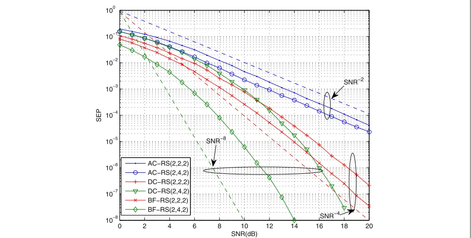
Figure 3 shows the overall system SEP performance of different transmission schemes to validate the advantages of the BF-RS scheme. We compare the BF-RS scheme with
0 2 4 6 8 10 12 14 16 18 20
10−8 10−7 10−6 10−5 10−4 10−3 10−2 10−1 100
SNR(dB)
SEP
Simulation
Upper bound in Proposition 1 Lower bound in Proposition 1 Asymptotic in Proposition 2
(3,2,2)
(2,2,2) (1,2,2)
0 2 4 6 8 10 12 14 10−6
10−5 10−4 10−3 10−2 10−1
SNR(dB)
SEP
EPA(2,2,2) IPA(2,2,2) OPA(2,2,2) EPA(2,3,2) IPA(2,3,2) OPA(2,3,2) EPA(3,2,3) IPA(3,2,3) OPA(3,2,3)
Fig. 6SEP performance comparison of the proposed IPA scheme, the EPA scheme and the OPA scheme
the Almouti code RS (AC-RS) and the diagonal code RS (DC-RS) with M = 2. Note that the AC-RS scheme also requires the full CSI for the relay selection process. It is shown that both the DC-RS and BF-RS schemes can achieve a full transmit and RS diversity gain ofd = KM. However, the diversity order of the AC-RS scheme is only
d = M. Comparing the SEP curves of AC-RS between (2, 2) and (2, 4), we can find that the RS is only helpful for coding gain, but not diversity gain in the AC-RS scheme. Overall, the BF-RS scheme outperforms the AC-RS and DC-RS schemes in all the SNR regions.
6.2 Analytical results
In Fig. 4, we illustrate the diversity gain of the BF-RS scheme with different configurations of(M,K). The
per-formance curves of the BF-RS scheme show the same decay trend with that of SNR−KM for all the configura-tions. The results show that the BF-RS scheme achieves a diversity gain ofd = KM. In addition, we can find that the performance of configurations of(M,K) =(3, 2)and (4, 2) are better than those of configurations of (2, 3) and (2, 4), respectively. From this, we can draw the conclusion that increasing the number of the source antennas is more helpful than increasing the number of the relays on the overall system SEP performance.
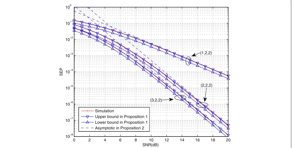
Figure 5 shows the SEP performance of a special case of the BF-RS scheme with(M,K,N) = (1, 2, 2),(2, 2, 2), and (3, 2, 2). The simulation result is within the curves of the theoretical upper and lower bounds. As shown in Fig. 5, the upper bound is very close to the simulated
SEP curve. The accuracy of upper bound can indicate that the approximations in the theoretical derivation of (19) are accurate. Meanwhile, it can be noticed that the lower bound is parallel with the simulated SEP curve with a constant gap in all SNR region. In summary, our derived bounds can predict the performance accurately. Further-more, the analytical asymptotic SEP and simulated SEP of the BF-RS scheme are presented as well. It is shown that, at the high SNR region, the asymptotic SEP given by (25) approaches the simulated SEP. The result has verified our analytical derivation.
6.3 PA
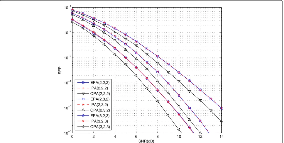
Figure 6 shows the SEP performance of the BF-RS scheme with the proposed IPA scheme. The results of the EPA and OPA [9] are also provided for comparison purposes. It can be observed that the SEP curves of the proposed IPA scheme are very close to the SEP curves of the EPA scheme. Meanwhile, it is shown that the gap between the performances of OPA and IPA is about 1–2 dB. This gain results from the fact that the more power consumption is used in OPA than that in IPA.
In Fig. 7, we compare the power consumption by the IPA and EPA schemes. The power cost of the EPA is the same as that of the OPA, i.e.,PT = 3. It can be observed that
(1,1) (2,2) (2,3) (2,4) (3,2) (4,2) 2.5
2.55 2.6 2.65 2.7 2.75 2.8 2.85 2.9 2.95 3
antennas number M and relays number K, (M, K)
power cost
E(O)PA IPA
Fig. 7Simulated transmission power consumption of the proposed IPA scheme, the EPA scheme, and the OPA scheme
show that the OPA outperforms the EPA in terms of the SEP once the total power constraint is adopted. Likewise, the IPA outperforms the EPA in terms of the power cost once the independent power constraint is adopted.
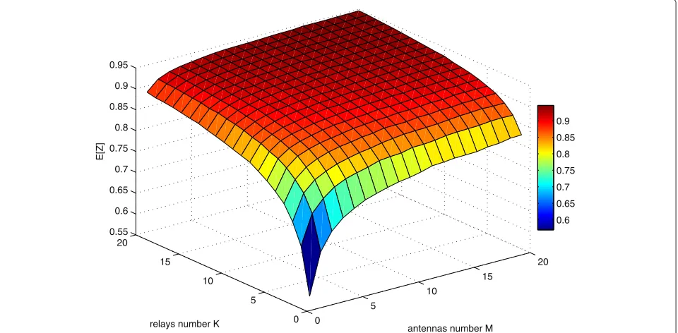
In Fig. 8, we plot the curved surface of the expectation of Z in terms of different numbers of source antennas and relays. It is shown that theE[Z] increases monoton-ically, which confirms that the effective power saving of
the proposed IPA scheme is obtained when the numbers of antennas of the sources and the relays are limited.
7 Conclusions
In this paper, we have studied the performance of vari-ous transmission schemes for multiple-antenna two-way relay systems with RS in terms of SEP. Specifically, we have focused on the performance of the BF-RS scheme as it
0
5
10
15
20
0 5 10 15 20 0.55 0.6 0.65 0.7 0.75 0.8 0.85 0.9 0.95
antennas number M relays number K
E[Z]
0.6 0.65 0.7 0.75 0.8 0.85 0.9
can outperform other schemes significantly. We derived the analytical upper and lower bounds of the end-to-end system SEP in the closed form as well as the asymptotic SEP expression in high SNR regime. The analytical per-formance predictions with the derived SEP expressions were verified by simulations. Based on individual power constraints, we also proposed an IPA scheme to save the total transmit power. Both analytical and simulated results indicated that the BF-RS scheme with IPA could save considerable amount of energy.
Endnote
1 We do not provide existing schemes’ performances in
detail in this paper, but their performances are shown in Section 6 by simulations.
Appendix
7.1 Proof of Lemma 1, Proposition 1
Appendix 7.1.We focus on the PDF ofγminR. Letγmk = distributed with 2Mdegrees of freedom, the PDF of γ1k
is fγ1k(ξ) = (Mξ−M1−)!1γMe
and CDF of γ2k can be easily obtained as well. Define
βk
Using order statistics, the CDF of the equivalent system SNRγminR= max
Consequently, using the binomial expansion, we can obtain the CDF of γminR. The PDF of γminR can be obtained by differentiating the CDF in (31).
Applying Lemma 1 in (19) and (21), the analytical end-to-end SEP in Proposition 2 can be obtained by the integral of [22, 2.33.10, 8.350.2].
7.2 Proof of Lemma 2, Proposition 2
Appendix 7.2.Differentiating the CDF in (31), we have
fγminR(x)=K
According to the Taylor series expansion formula and the limit theory, we can approximate the PDF by polynomial terms as
By (19), the SEP of the overall system is upper bounded by
Applying Lemma 2 in [23], the average SEP of the overall system is given by
PREtoE≤3
7.3 Proof of Lemma 3
Since X = η1RandY = ηR2 are RVs with generalized
can be expressed as
FZ(z)=2Pr{Z≤34z,X≤Y5}
Due to the symmetry, it is straightforward to obtain I2 fromI1. Then, the CDFFZ(z)=I1+I2=2I1.
7.4 Proof of Proposition 3
Based on the RS criterion as (15), when K→ ∞, it is obvious to see lim
ζ = min(X,Y), ψ = max(X,Y). Without loss of gen-to symmetry, it is straightforward gen-to obtainI4 forI3by exchangexandy. The expectation ofZ, whenK→ ∞, is
lim
K→∞E[Z]=1.
Let us now consider the expectation whenM→ ∞and
K ∈ N+. Since X = ηR1 and Y = ηR2 are general-ized Rayleigh RVs,X2andY2are chi-square distributed with 2Mdegrees of freedom. Using high-order moments of the generalized Rayleigh distribution [15, 2-1-138] and Stirling’s formula [24], we find
E[X]=
variation forXis obtained as lim
M→∞
It completes the proof.
Competing interests
The authors declare that they have no competing interests.
Acknowledgements
This work is supported in part by the National Science Foundation of China (NSFC, Grant No. 61471008), the Specialized Research Fund for the Doctoral Program of the Ministry of Education of China (Grant No. 20120001120125), and the National Natural Science Foundation of Beijing (Grant No. 4144075). The correspondence author is Chen Chen (E-mail: [email protected]).
Author details
1State Key Laboratory of Advanced Optical Communication Systems and
Networks, Peking University, 100871 Beijing, China.2Representative Office in
Chengdu of Information Department, 610041 Chengdu, China.
Received: 16 January 2015 Accepted: 6 July 2015
References
1. T Cui, F Gao, T Ho, A Nallanathan, inProc. IEEE ICC. Distributed space-time coding for two-way wireless relay networks (IEEE Beijing, China, 2008), pp. 3888–3892
2. D To, J Choi, IM Kim, Error probability analysis of bidirectional relay systems using Alamouti scheme. IEEE Commun. Lett.14(8), 758–760 (2010) 3. FK Gong, JK Zhang, G Jian-hua, Distributed concatenated Alamouti codes
for two-way relaying networks. IEEE Wireless Commun. Lett.1(3), 197–200 (2012)
4. C Chen, L Bai, B Wu, J Choi, Relay selection and beamforming for cooperative bi-directional transmissions with physical layer network coding. IET Commun.5(14), 2059–2067 (2011)
5. X Jia, L Yang, H Fu, Tight performance bounds for two-way opportunistic amplify-and-forward wireless relaying networks with TDBC protocols. EURASIP J. Wirel. Commun. Netw.1(192), 1–8 (2012)
6. LS Jayasinghe, N Rajatheva, M Latva-Aho, Robust precoder-decoder design for physical layer network coding-based MIMO two-way relaying system. EURASIP J. Wirel. Commun. Netw.1(137), 1–16 (2013)
7. Q Zhou, Y Li, F Lau, B Vucetic, Decode-and-forward two-way relaying with network coding and opportunistic relay selection. IEEE Trans. Commun. 58(11), 3070–3076 (2010)
8. S Beygi, M Kafashan, H Bahrami, T Le-Ngoc, M Maleki, Space-time trellis codes for two-way relay MIMO channels with single-antenna relay nodes. IEEE Trans. Veh. Technol.62(8), 4040–4045 (2013)
9. T Do, J Wang, L Song, Y Kim, Joint relay selection and power allocation for two-way relaying with physical layer network coding. IEEE Commun. Lett. 17(2), 301–304 (2013)
10. L Song, Relay selection for two-way relaying with amplify-and-forward protocols. IEEE Trans. Veh. Technol.60(4), 1954–1959 (2011)
11. C Zhang, J Ge, J Li, Y Hu, Fairness-aware power allocation for asymmetric two-way AF relaying networks. Electron. Lett.48(15), 959–961 (2012) 12. S Talwar, Y Jing, S Shahbazpanahi, Joint relay selection and power
allocation for two-way relay networks. IEEE Signal Process. Lett.18(2), 91–94 (2011)
13. S Alamouti, A simple transmit diversity technique for wireless communications. IEEE J. Sel. Areas Commun.16(8), 1451–1458 (1998) 14. EG Larsson, P Stoica,Space-time block coding for wireless communications.
(Cambridge University Press, New York, 2003)
15. J Proakis,Digital communications, 4th edition. (McGraw-Hill, New York, 2000)
16. TKY Lo, Maximum ratio transmission. IEEE Trans. Commun.47(10), 1458–1461 (1999)
17. RHY Louie, Y Li, HA Suraweera, B Vucetic, Performance analysis of beamforming in two hop amplify and forward relay networks with antenna correlation. IEEE Trans. Wireless Commun.8(6), 3132–3141 (2009) 18. Y Lu, N Yang, H Dai, X Wang, Opportunistic decode-and-forward relaying
with beamforming in two-wave with diffuse power fading. IEEE Trans. Veh. Technol.61(7), 3050–3060 (2012)
20. M Soysa, HA Suraweera, C Tellambura, HK Garg, Partial and opportunistic relay selection with outdated channel estimates. IEEE Trans. Commun. 60(3), 840–850 (2012)
21. M Abramowitz, IA Stegun,Handbook of mathematical functions with formulas, graphs, and mathematical tables, 9th Edition. (Dover, New York, 1970)
22. IS Gradshteyn, IM Ryzhik,Table of integrals, series, and products, 7th edition. (Academic, New York, 2007)
23. Z Wang, G Giannakis, A simple and general parameterization quantifying performance in fading channels. IEEE Trans. Commun.51(8), 1389–1398 (2003)
24. RB Paris, D Kaminsky,Asymptotics and the Mellin-Barnes integrals. (Cambridge University Press, New York, 2001)
Submit your manuscript to a
journal and benefi t from:
7Convenient online submission
7Rigorous peer review
7Immediate publication on acceptance
7Open access: articles freely available online
7High visibility within the fi eld
7Retaining the copyright to your article