Important Upgrade Information
• To use the IntraMail enhancements provided by software versions 03.2*.** and higher, you must use the NEC IntraMail Utility version 1.2 to upgrade your IntraMail CompactFlash card. If you don’t upgrade your card, the new features will not be available.
• If upgrading from version 3 software prior to 03.10.08 using telephone programming, you must reprogram the options in 1808-IntraMail Subscriber Mailbox Options, 8005-Intra-Mail Master 8005-Intra-Mailbox Options, and 8006-IntraMail Routing Mailboxes after the upgrade. • To avoid having to reprogram the above options, use the latest version of the DS1000/2000
System Administrator to backup and restore the site database.
This manual has been developed by NEC Unified Solutions, Inc. It is intended for the use of its customers and service personnel, and should be read in its entirety before attempting to install or program the system. Any comments or suggestions for improving this manual would be appreciated. Forward your remarks to:
NEC Unified Solutions, Inc.
4 Forest Parkway Shelton, CT 06484
www.necunifiedsolutions.com
Nothing contained in this manual shall be deemed to be, and this manual does not constitute, a warranty of, or representation with respect to, any of the equipment covered. This manual is subject to change without notice and NEC Unified Solutions, Inc. has no obligation to provide any updates or corrections to this manual. Further, NEC Unified Solutions, Inc. also reserves the right, without prior notice, to make changes in equipment design or components as it deems appropriate. No
representation is made that this manual is complete or accurate in all respects and NEC Unified Solutions, Inc. shall not be liable for any errors or omissions. In no event shall NEC Unified Solutions, Inc. be liable for any incidental or consequential damages in connection with the use of this manual. This document contains proprietary information that is protected by copyright. All rights are reserved. No part of this document may be photocopied or reproduced without prior written consent of NEC Unified Solutions, Inc.
Table of Contents
Table of Contents
Chapter 1 Features . . . 1
Introduction . . . .1
Before Reading This Section . . . .1
Using This Section . . . .1
DS2000 System Configuration . . . .3
DS2000 Load Factor . . . .3
DS2000 Load Factor Calculations. . . .3
Examples of Typical DS2000 4-Slot Cabinet Configurations. . . .5
Examples of Typical DS2000 8-Slot Cabinet Maximum Configurations . . . .5
DS2000 Hardware Default Setup with Automatic Slot Configuration . . . .5
DS1000 System Configuration . . . .6
DS1000 Load Factor . . . .6
DS1000 System Load Factor Calculations . . . 6
DS1000 Default Setup . . . .7
Initial System Startup. . . .8
Default Feature Setup . . . .8
Initial Startup Programming . . . .9
Charts and Illustrations . . . .11
2-OPX Module . . . .22
2500 Sets / Single Line Telephones . . . .23
Account Codes . . . .24
Optional (Unforced) Account Codes . . . .24
Forced Account Codes. . . .24
Verified Account Codes . . . .24
Using Account Codes and Speed Dial. . . .24
Using Account Codes with Last Number Redial and Save . . . .25
Account Codes and Emergency Calls . . . .25
DSS Console Account Code Key . . . .25
General Account Codes Programming . . . .28
Optional (Unforced) Account Codes Programming . . . .28
Forced Account Codes Programming . . . .29
Verified Account Codes Programming . . . .29
Account Codes Programming Examples . . . .30
Alphanumeric Display . . . .33
Attendant Call Queuing . . . .35
Operator Call Key . . . .35
Attendant Position . . . .37
Table of Contents
Renumbering Extensions and Trunks . . . .52
Background Music . . . .53
Barge In (Intrusion) . . . .56
Battery Backup. . . .58
Call Coverage Keys . . . .59
Call Coverage Guard Timer. . . .59
Call Forwarding . . . .63
Call Forwarding Chaining . . . .63
Call Forwarding Cancel. . . .63
Call Forwarding Key . . . .63
Call Forwarding Toggle in a Personal Speed Dial Bin . . . .64
Call Forwarding Confirmation Tone . . . .64
Call Forwarding Timers. . . .66
Call Forwarding Off Premise . . . .75
Call Forwarding Off Premise Example . . . .75
Call Timer . . . .85
Call Waiting / Camp-On . . . .88
Callback . . . .92
Caller ID. . . .95
Single and Multiple Message Format Compatibility. . . .95
Caller ID on the SMDR Report . . . .95
Caller ID Integration with Voice Mail. . . .96
Second Call Caller ID (Extension Level Call Waiting Caller ID). . . .96
Third Party Caller ID Check . . . .96
Caller ID Display Separator. . . .96
Caller ID to Single Line Telephones . . . .96
DSP-Based Caller ID. . . .96
Caller ID Logging . . . .102
Caller ID Logging Enhancements . . . .102
Caller ID and Answering Machines . . . .103
Some Common Caller ID Logging Examples . . . .109
22-Button and 34-Button Display Telephone Operation. . . .110
Super Display Telephone Operation . . . .111
Central Office Calls, Answering . . . .113
Answering Priority. . . .113
Overflow . . . .113
Single Ring Option for Single Line Sets . . . .113
Central Office Calls, Placing . . . .119
Expanded Dial Buffering. . . .119
Store and Forward . . . .119
Store and Forward with Forced Account Codes . . . .120
Check Key . . . .131
Class of Service . . . .133
Conference . . . .142
Conference, Meet-Me . . . .145
Table of Contents
DID Call Handling . . . .157
An Overview of DID Call Handling . . . .157
How Call Forwarding and Extension Hunting Interact with DID Calls . . . .159
DID Call Handling with Call Forwarding and Extension Hunting . . . .160
DID Station Intercept and Trunk Overflow. . . .161
Direct Inward Dialing Programming . . . .165
ANI/DNIS Programming. . . .168
Direct Inward Line . . . .170
Direct Station Selection (DSS) . . . .177
Direct Station Selection (DSS) Console . . . .180
Direct Trunk Access. . . .191
Directed Call Pickup . . . .193
Directory Dialing . . . .195
Directory Dialing Display Enhancements . . . .195
Display, Alphanumeric . . . .199
Distinctive Ringing . . . .200
The Distinctive Ringing Hierarchy . . . .201
Understanding Ring Types and Ring Sets . . . .201
The Basics of How to Change the “Sound” of a Ring Type . . . .202
When Multiple Calls Ring an Extension . . . .202
Programming Guidelines . . . .202
Do Not Disturb. . . .220
Do Not Disturb BLF for Hotline and Call Coverage Keys . . . .221
Do Not Disturb Override . . . .224
Door Box . . . .226
Equal Access Compatibility. . . .232
Expanded Database . . . .233
Default Numbering in DS1000 . . . .234
Default Numbering in DS2000 . . . .235
Extended Ringing. . . .237
Extension Hunting . . . .239
Circular Hunting . . . .239
Terminal Hunting. . . .240
Uniform Call Distribution (UCD) Hunting . . . .241
Extension Hunting Timers. . . .248
Extension Locking . . . .256
Walking Class of Service and Extension Locking . . . .256
Flash . . . .264
Flash for Single Line Extensions. . . .264
Flexible Numbering Plan . . . .267
Forced Trunk Disconnect. . . .271
Group Call Pickup . . . .273
Group Listen . . . .277
Group Ring. . . .279
Overflow for Group Ring Calls . . . .279
Table of Contents
System (Regular) Hold . . . .296
Exclusive Hold. . . .296
Automatic Hold . . . .296
Intercom Hold . . . .296
Distinctive Flash Rate on Recall . . . .297
Enhanced Hold Recall Display . . . .297
Using Hold at a Single Line Extension . . . .301
Hotline . . . .302
Interactive Soft Keys . . . .306
Keyset Soft Keys . . . .308
Super Display Soft Keys . . . .317
Soft Key Index. . . .327
Call States . . . .335
Intercom . . . .339
Handsfree Answerback and Forced Intercom Ringing . . . .339
Key Ring . . . .344
Overflow for Key Ring Calls. . . .344
Language Selection . . . .348
Language Selection and SMDR. . . .348
Last Number Redial . . . .351
Enhanced Last Number Redial . . . .351
Line Keys . . . .356
Answering Priority. . . .356
Loop Keys . . . .360
Switched Loop Keys . . . .360
Fixed Loop Keys . . . .360
Answering Priority. . . .360
Meet-Me Conference . . . .365
Message Waiting . . . .368
Single Line Telephone Message Waiting Enhancements . . . .368
Microphone Mute. . . .373
Handsfree Reply Soft Key . . . .373
Modem Cut-Through . . . .376
Modem Setup. . . .376
Monitor / Silent Monitor . . . .378
Multiple Directory Numbers . . . .380
Music on Hold . . . .381
Names for Extensions and Trunks . . . .384
Night Service / Night Ring. . . .389
Night Service Keys . . . .389
Basic Night Service Types. . . .389
Off-Hook Signaling . . . .394
Off-Hook Signaling for Trunk Calls . . . .394
Off-Hook Signaling for Intercom Calls. . . .394
Off-Hook Signaling for Hotline Calls . . . .394
Table of Contents
Page Relay Control . . . .410
Trunk Ringing Over External Page . . . .410
Intercom Ring Over External Page . . . .410
Door Chime Over External Page . . . .411
Background Music Over External Page . . . .411
Ring Over Page Volume Adjustment . . . .411
Paging, Meet-Me Conference . . . .419
Park . . . .420
Distinctive Flash Rate on Recall . . . .421
Enhanced Personal Park Orbit Recall Display . . . .421
Enhanced System Park Orbit Recall Display . . . .422
PBX/Centrex Compatibility . . . .426
PBX/Centrex Access Codes . . . .426
PC Program (System Administrator) . . . .429
Programming List . . . .430
Prime Line Preference . . . .431
Idle Prime Line . . . .431
Intercom Prime Line . . . .431
Prime Line vs. Ringing Line Preference . . . .431
Privacy . . . .435
Privacy Release Groups . . . .437
Privacy Release Guard Timer . . . .437
Private Line . . . .440
Programmable Function Keys . . . .444
Programmable Idle Menu Soft Keys (Super Display) . . . .450
Pulse to Tone Conversion . . . .453
Regional Defaults. . . .455
Removing Trunks and Extensions From Service. . . .457
Reverse Voice Over . . . .459
Ring Groups . . . .462
Ringdown Extension . . . .463
Ringing Line Preference . . . .465
Save Number Dialed . . . .468
Selectable Display Messaging . . . .471
Silent Monitor . . . .478
Single Line Telephones . . . .479
Soft Keys . . . .480
Speed Dial . . . .481
System Speed Dial. . . .481
Personal Speed Dial. . . .481
Allocating Speed Dial Blocks . . . .481
Unique Speed Dial Entries. . . .482
Storing Trunk Routing in a Speed Dial Bin. . . .482
Centrex Compatibility . . . .483
Chaining Bins for Dialing Long Numbers. . . .483
Table of Contents
SMDR Report Definitions . . . .499
SMDR Report Format . . . .499
System Diagnostics . . . .505
System Identification . . . .506
System Programming Backup and Restore . . . .508
DS2000 PC Cards . . . .508
Data Base Compatibility . . . .508
DS1000 Database Transfer Utility. . . .508
System Programming List . . . .511
System Programming Password Protection . . . .514
System Timers . . . .516
System Timers, Stations. . . .519
System Timers, Trunks . . . .524
Rules for Detecting Normal CO (Single) Ring . . . .527
Rules for Detecting Special (Double) Ring . . . .528
Rules for Detecting Loop Current . . . .528
T1 Trunking . . . .530
ANI/DNIS Support . . . .530
FSK Caller ID . . . .530
E1 Trunking . . . .531
T1 Programming . . . .534
ANI/DNIS and Caller ID Programming . . . .535
E1 Programming . . . .536
Tandem Trunking / Unsupervised Conference . . . .538
Using Trunk-To-Trunk Transfer to Set Up a Tandem Call. . . .541
Tie Lines . . . .542
Time and Date . . . .546
Toll Restriction . . . .549
The Toll Restriction Tables . . . .550
Toll Restriction Overview . . . .550
Default Toll Restriction Configuration . . . .551
Some Common Toll Restriction Examples . . . .556
Transfer . . . .558
Distinctive Flash Rate on Recall . . . .558
Enhanced Recall Display. . . .559
Handsfree Transfer . . . .559
Interaction Between Call Forwarding, Extension Hunting, and Transfer Recall . . . .560
Trunk Group Routing. . . .566
Trunk (Line) Queuing / Trunk Callback . . . .569
Trunk Queuing. . . .569
Trunk Callback . . . .569
Trunk Queuing Priority . . . .569
Trunk Groups . . . .572
Trunk Timers . . . .576
User Programmable Features . . . .577
Table of Contents
Voice Mail Overflow. . . .581
Message Center Mailbox . . . .582
Interactive Soft Key Shows New Messages . . . .582
Setting Up NVM-Series Voice Mail . . . .582
DS1000 Ring Assignments and Voice Mail Ports. . . .582
Improved Handling of Extensions in Do Not Disturb . . . .582
Programming Your Voice Mail . . . .584
Simplified External Voice Mail Programming . . . 584
Setting Up VANGARD Mail for NVM-1000/2000 . . . .585
Setting Up NVM-2e and NVM-1000/2000 . . . .585
Setting Up Older NVM-Series Voice Systems without DS1000/2000 Integration. . . . .586
Call Forwarding Timers and Voice Mail. . . .591
Voice Over . . . .600
Volume Controls . . . .603
Enhanced Volume and Contrast Control . . . .603
Enhanced Volume and Contrast Control Operation . . . .604
Walking Class of Service . . . .606
Walking Class of Service and Extension Locking . . . .606
Table of Contents
Chapter 2 Programming . . . 611
Introduction to Programming. . . .611
Before You Start Programming . . . .611
0100 - Class of Service . . . .617
0101 - Class of Service Options . . . .617
0200 - Tenant Options . . . .628
0201 - Tenant Option Programming . . . .628
0202 - Ring Over External Page Options . . . .632
0203 - UNA Ringing Over External Page . . . .634
0300 - System Options . . . .635
0301 - System Options (Part 1) . . . .635
0302 - System Identification . . . .639
0400 - Timers . . . .642
0401 - System Timers . . . .642
0402 - Trunk Timers . . . .647
0403 - Station Timers . . . .655
0404 - Analog Station Timers . . . .658
0405 - T1/E1 Trunk Timers. . . .661
0406 - T1 Trunk Timers . . . .665
0407 - E1 Trunk Timers . . . .667
0408 - E1 MFC Timers . . . .669
0500 - System Numbering . . . .671
0501 - Numbering Plan . . . .671
0502 - Station Extension Assignments . . . .676
0503 - Trunk Extension Assignments . . . .677
0505 - Extension Swap Utility. . . .678
0510 - ACD/UCD Master Extension Numbers and Names . . . .679
0511 - Ring Group Master Extension Numbers and Names . . . .681
0600 - Toll Restriction . . . .683
0601 - Configure Toll Level Options . . . .683
0602 - 1010 + XXX Equal Access Dialing . . . .686
0603 - 1 + NPA/NXX Dialing 3-Digit Table . . . .688
0604 - 1 + NPA + NXX Dialing 6-Digit Table . . . .690
0605 - NPA/NXX Dialing 3-Digit Table. . . .692
0606 - NPA + NXX Dialing 6-Digit Table . . . .694
0610 - PBX Access Codes Table. . . .696
0800 - Display Messages . . . .697
0801 - Selectable Display Messages . . . .697
1000 - Trunk Programming . . . .699
1001 - Trunk Port Description. . . .699
1002 - Trunk Groups . . . .709
1003 - Trunk Options. . . .712
1004 - Line Group Access . . . .716
1005 - Trunk Caller ID Logging Group . . . .717
1006 - Trunk Line Access . . . .718
Table of Contents
1302 - 10 Digit Local Calls . . . .725
1303 - Home Area (HNPA) Codes . . . .726
1304 - Home Area (HNPA) Exception List . . . .728
1305 - Foreign Area (FNPA) Exception List . . . .730
1400 - DID Options . . . .732
1401 - Number of DID Digits . . . .732
1402 - DID Translation Table . . . .733
1403 - DID MFC Dialing Category. . . .736
1700 - Key Programming. . . .737
1701 - Programmable Function Key Assignments . . . .737
1702 - Personal Speed Dial . . . .743
1703 - DSS Key Assignment. . . .745
1704 - DSS Console Key Assignment. . . .746
1705 - Soft Key Configuration . . . .752
1800 - Extension Options. . . .754
1801 - Extension Port Description. . . .754
1802 - Extension Options (Part 1) . . . .758
1803 - Extension Line Access Assignments . . . .763
1804 - Extension Trunk Group Access . . . .765
1805 - Ring Assignments. . . .767
1806 - Ring Type Configuration . . . .769
1807 - Extension Options (Part 2) . . . .771
1808 - IntraMail Subscriber Mailbox Options. . . .775
8000 - Voice Mail . . . .776
8001 - Voice Mail Setup . . . .776
8002 - Voice Mail Port Options (Part 1) . . . .777
8003 - Voice Mail Port Options (Part 2) . . . .780
8004 - IntraMail System Options . . . .781
8005 - IntraMail Master Mailbox Options. . . .782
8006 - IntraMail Routing Mailboxes . . . .783
8007 - IntraMail Answer Tables . . . .784
8008 - IntraMail Dial Action Tables . . . .785
9800 - System Utilities, Part 1 . . . .786
9801 - Copy Command . . . .786
9803 - Ring Tone Setup. . . .789
9804 - Initialize Caller ID Log Utility. . . .791
9900 - System Utilities, Part 2 . . . .792
9901 - Reset Station Port . . . .792
9902 - Set Up Stations (DS1000) . . . .793
Setting Up the 2-OPX Module Secondary Channel in DS1000 . . . 794
9902 - Set Up Stations (DS2000) . . . .796
Setting Up the 2-OPX Module Secondary Channel in DS2000 . . . 796
9903 - Set Up Trunks (DS1000) . . . .801
9903 - Set Up Trunks (DS2000) . . . .803
9904 - T1/E1 Configuration. . . .807
Introduction
Chapter 1
Features
Introduction
Introduction
Before Reading This Section
This section provides detailed information on the system’s features. If you don’t know what the var-ious features are, review the Table of Contents for this section and the manual’s Index. After reviewing, turn back to this section for the specifics.
Using This Section
The features in this section are in alphabetical order, like a dictionary. This section subdivides each feature definition into headings as follows:
Description
Read Description to get an overview of the feature. Along with the feature’s description are the Conditions and Default Setting. Conditions provides the feature’s operational limits (if any). Default Setting outlines how the feature works with the default (factory installed) Programming List. When initially installed, the system uses the default setting. For specific default settings on each program, refer to the chart at the end of this manual.
Introduction
To check your system’s software version:
1. Do not lift the handset, do not press SPK, and do not press ICM. 2. Dial 8.
Your system’s software version displays.
Programming Guide
The Programming Guide is an easy-to-use chart that guides you step-by-step through programming the feature. If you’re not sure how to set up a feature, start first with the Programming Guide.
Programming List
Programming List explains the system Programming List that lets you customize the feature. Some features require Programming List; others don’t. If you decide to customize a feature, use Section 2 to enter the change into the system.
Other Related Features
Read this part to learn how the feature interacts with other features.
Feature Operation
This part provides you with instructions on how to use each feature. These instructions are also pro-vided in the following documents:
● DS1000/2000 Feature Handbook (P/N 80000MFH**)
● DS1000/2000 Multibutton Telephone Quick Reference Guide (P/N 80000MBG**)
● DS1000/2000 Analog Single Line Quick Reference Guide (P/N 80000SLT**)
DS2000 System Configuration
DS2000 System Configuration
DS2000 Load Factor
The total number of components you can install and connect to your DS2000 system depends on power supply capacity and the System Load Factor. Read the following notes, then turn to DS2000 Load Factor Calculations below to calculate the System Load Factor.
DS2000 Load Factor Calculations
The combination of trunks, extensions, 2-OPX Modules and DSS Consoles you can connect to your DS2000 system may be limited by the System Load Factor. Use the DS2000 System Load Fac-tor Calculations chart on the next page to verify your system’s configuration. When entering data on the chart, for each installed item make entries for each Load Type. There are two Load Types to consider: 5 VDC and 40 VDC.
To check your system configuration:
1. Indicate the quantity for each PCB, DSS Console, and 2-OPX Module installed in the
Qty column.
The number of keysets and single line sets does not affect the System Load Factor. 2. For each item for each Load Type, multiply the Qty times the Load and enter the value in the
Total column.
For example, two 16DSTU PCBs have a load of 6 for 5 VDC and 40 for 40 VDC. 3. Add up the entries in each Total column and enter the values in Item 1: Load Type Totals. 4. Review Item 2: Power Supply Capacity and determine the capacity of the power supplies
installed in your system.
5. Compare the capacities in Item2 to your entries in Item1. Item1 must always be equal to or
Notes for Version 3 Software
4 Slot Cabinets
• Do not install more than 2 16DSTU PCBs under any circumstances. • The first 16DSTU PCB you install must be in the first slot (CN1).
• Maximum configuration is 112ports (although this limit cannot be achieved in a 4 Slot Cabinet).
• The total of all extensions and trunks cannot exceed 112.
• Always use the System Load Factor Table to check you system configuration.
8 Slot Cabinets
• Do not install more than 2 16DSTU PCBs for each power supply. (Install your power sup-plies in the following order: slot CN101, slot CN103, slot CN102.)
• The first 16DSTU PCB you install must be in the first slot (CN1). • The total of all extensions and trunks installed cannot exceed 112. • Maximum configuration is 112 ports.
• Always use the System Load Factor Table to check your system configuration.
DS2000 System Configuration
DS2000 System Load Factor Calculations
Description Qty
Load Type
5 VDC 40 VDC
Load Total Load Total
CPU PCB 1 6 6 0 0
16DSTU PCB 3 20
4ASTU PCB 3 5
8ASTU PCB 5 8
4ATRU PCB 4 0
8ATRU PCB 8 0
T1 PCB 8 0
UltraMail PCB (FMS) 19 0
UltraMail 2000 PCB (VMS) 0 6
Telephones (Keysets and SLTs) 0 0
110-Button DSS Console 0 2
24-Button DSS Console 0 1
2-OPX Module 0 3
Item 1: Load Type Totals (Cannot exceed Item 2: Power Supply Capacity.)
Item 2: Power Supply Capacity
If you have one power supply installed, the capacity is: If you have two power supplies installed, the capacity is: If you have three power supplies installed, the capacity is:
5 VDC = 40 5 VDC = 80 5 VDC = 120
40 VDC = 48 40 VDC = 80 40 VDC = 120
Notes:
• A 4 slot cabinet can only have 1 power supply.
• An 8 slot cabinet can have up to 3 power supplies. You cannot have more than two 16DSTU PCBs per power sup-ply, regardless of System Load Factor calculations.
• Exceeding the allowed Load Type Total (Item 1) will cause the system’s power supplies to automatically shut down and/or cause erratic system operation.
• Total DSS Consoles installed cannot exceed 4.
DS2000 System Configuration
Examples of Typical DS2000 4-Slot Cabinet Configurations
● 16 x 32 (16 trunks and 32 digital extensions)
Recommended for sites with no external Voice Mail and high trunk usage.
● 24 x 16 (24 trunks and 16 digital extensions)
Recommended for sites with no external Voice Mail and very high trunk usage.
● 8 x 16 x 16 (8 trunks, 16 digital extensions and 16 analog extensions)
Recommended for sites with external Voice Mail, normal trunk usage and high analog extension usage.
● 16 x 16 x 8 (16 trunks, 16 digital extensions and 8 analog extensions)
Recommended for sites with external Voice Mail, high trunk usage and high analog exten-sion usage.
● 8 x 32 x 8 (8 trunks, 32 digital extensions and eight analog extensions)
Recommended for sites with external Voice Mail, normal to low trunk usage and low analog extension usage.
Examples of Typical DS2000 8-Slot Cabinet Maximum Configurations
● 32 x 64 (32 trunks and 64 digital extensions)
Recommended for sites with no external Voice Mail and high trunk usage. This configuration requires 2 power supplies.
● 48 x 32 (48 trunks and 32 digital extensions)
Recommended for sites with no external Voice Mail and very high trunk usage. This confi gu-ration requires 1 power supply.
● 16 x 32 x 32 (16 trunks, 32 digital extensions and 32 analog extensions)
Recommended for sites with external Voice Mail, normal trunk usage and high analog exten-sion usage. This configuration requires 2 power supplies.
● 32 x 32 x 16 (32 trunks, 32 digital extensions and 16 analog extensions)
Recommended for sites with external Voice Mail, high trunk usage and high analog extension usage. This configuration requires 2 power supplies.
● 16 x 64 x 16 (16 trunks, 64 digital extensions and 16 analog extensions)
Recommended for sites with external Voice Mail, normal to low trunk usage and low analog extension usage. This configuration requires 3 power supplies.
DS2000 Hardware Default Setup with Automatic Slot Configuration
Automatic Slot Configuration automatically sets up your system’s PCBs when you initially power up the system. There is no longer a factory-installed default configuration, and you don’t have to use system programming to activate PCBs after you plug them in. Remember, you should always plug a 16DSTU PCB into slot CN1.DS1000 System Configuration
DS1000 System Configuration
DS1000 Load Factor
DS1000 System Load Factor Calculations
The combination of extensions, Digital Door Boxes, 2-OPX Modules, and DSS Consoles you can connect to your system may be limited by the System Load Factor. Use the DS1000 System Load Factor Calculations chart below to verify your system’s configuration.
To check your system configuration:
1. Indicate the quantity for each item installed in the Qty column.
2. For each item, multiply the Qty times the Load Factor and enter the value in Total Load. 3. Add all the values in the Total Load column and enter the value in Item1.
4. Compare the entry in Item2 to your entry in Item1. Item1 must always be equal to or less than the entry in Item2.
Do not operate your system if the System Load Factor total (Item 1) exceeds the allowable load of 30 (Item 2).
DS1000 System Load Factor Calculations
Description Load Factor Qty Total Load
Digital Telephone and Digital
Door Box 1
Analog Telephone 1
Analog Door Box 0
24-Button DSS Console 1
110-Button DSS Console 2
Total DSS Consoles installed cannot exceed 4
2-OPX Module 3
Item 1: Total load for this configuration
DS1000 System Configuration
DS1000 Default Setup
Using the factory installed default configuration, your DS1000 system provides:
For more on installing the DS1000 Expansion PCB, refer to the DS1000 Quick Setup Guide (P/N 80200QSET**) that came with your system.
Base Expansion Total
Trunks 3 3 6
Digital Extensions 8 8 16
Analog Extensions 4 4 8
Analog Door Boxes 1 1 2
Relays 1 1 2
Page Output 1 - 1
Initial System Startup
Initial System Startup
Default Feature Setup
Trunks
● All trunks are loop start DTMF.
Use Program 1001 - Trunk Circuit Type (page 699) to change this assignment.
● In DS2000, trunks 1-12 ring on line keys 1-12 for extensions 300-315. All other extensions are lamp only for trunks 1-12. Trunks 13-64 do not appear on line keys.
● In DS1000, trunks 1-6 ring on line keys 1-6. (Trunks 4-6 require the Expansion Board.)
● Use User Programmable Features (page 577) code #RAL or Program 1805 - Ring Assign-ments (page 767) to customize ringing.
Extensions
● The circuit types for keyset extensions are automatically set when the extension is plugged in. Use Program 1801 - Extension Circuit Type (page 754) to change this assignment.
● Keyset users can place outside calls by:
- Pressing a line key and dialing the outside number.
See Central Office Calls, Placing (page 119) for more. - Pressing ICM, dialing 9, and dialing the outside number.
See Trunk Group Routing (page 566) for more.
● Line Dial-Up and Direct Trunk Access are disabled.
See Central Office Calls, Placing (page 119) for more.
● At the attendant’s extension (300), key 11 is the Night (System Mode System) key and the last key on the phone (12 or 24, depending on telephone model) is the Operator Call Key.
Pressing the Night (System Mode System) key puts the system in the night mode. See Night Service / Night Ring on page 389.
Initial System Startup
Initial Startup Programming
Initial Startup Programming (Page 1 of 2)
Step 1: Check the system defaults.
• If you have a DS2000, refer to DS2000 Hardware Default Setup with Automatic Slot Configuration on page 5.
• If you have a DS1000, refer to DS1000 Default Setup on page 7.
• To check the feature defaults, refer to Default Feature Setup on page 8.
Step 2: Enter the programming mode.
• From any display telephone:
Press ICM + #*#* + Password + HOLD. • The default system passwords are:
Installer (level 3) = 372000
System Administrator 2 (level 2) = 9999 System Administrator 3 (level 1) = 0000
Step 3: Assign the correct circuit type to your installed trunks.
• In Program 1001 - Trunk Circuit Type (page 699), enter the correct circuit type for each installed trunk. Analog trunk types are:
51 = Loop start DTMF 52 = Loop start DP
Step 4: By default, each extension has full access to each trunk. Do you want to change this assignment?
• For each extension in Program 1803 - Extension Line Access Assignments (page 763), assign the access options for each trunk. The options are:
0 = No access 1 = Incoming only 2 = Outgoing only 3 = Full access
• Use Program 9801 - Copy Command (page 786), to simplify your programming.
• In Program 1803 - Extension Line Access Assign-ments (page 763), make no changes from the default assignments.
If yes
Initial System Startup
Step 5: Do you want to change the way extensions ring for incoming trunk calls?
• For each extension in Program 1805 - Ring Assignments (page 767), assign ringing for each trunk. The options are:
1 = Lamp only (day and night) 2 = Ringing day and night
3 = Night Ring only, lamp during the day 4 = Delay ring day and night
• Use Program 9801 - Copy Command (page 786), to simplify your programming.
• The system attendant (extension 300) can put these trunks in the night mode by pressing their preassigned Night (System Mode System) key (key 11).
• For each extension in Program 1805 - Ring Assignments (page 767), make no changes from the default assignments.
Step 6: Does your system have external Voice Mail?
• Turn to Voice Mail on page 580 and review the required Voice Mail programming.
• Go to the next step.
Step 7: Do you want to change the default system passwords?
• In Program 9905 - Password (page 811), change the passwords from their default settings.
• In Program 9905 - Password (page 811), do not change the passwords from their default settings.
Step 8: Do you want to return the system to its factory installed (default) programming?
• In Program 9999 - System Initialization (page 822), reinstate the factory installed pro-gramming. This erases all your programming and returns the system to its initial default set-tings.
• In Program 9999 - System Initialization
Initial Startup Programming (Page 2 of 2)
If yes
If no
If yes
If no
If yes
If no
Charts and Illustrations
Charts and Illustrations
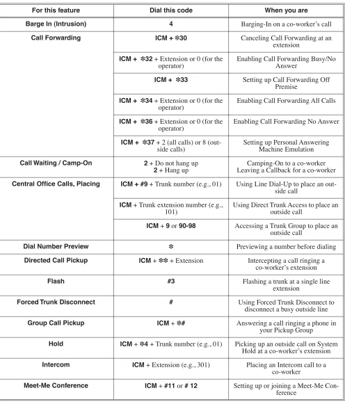
Table 1: Dial Codes (by Feature)
For this feature Dial this code When you are
Barge In (Intrusion) 4 Barging-In on a co-worker’s call
Call Forwarding ICM + ✽30 Canceling Call Forwarding at an extension
ICM + ✽32 + Extension or 0 (for the
operator) Enabling Call Forwarding Busy/No Answer
ICM + ✽33 Setting up Call Forwarding Off Premise
ICM + ✽34 + Extension or 0 (for the
operator) Enabling Call Forwarding All Calls
ICM + ✽36 + Extension or 0 (for the
operator) Enabling Call Forwarding No Answer
ICM + ✽37 + 2 (all calls) or 8
(out-side calls) Setting up Personal Answering Machine Emulation
Call Waiting / Camp-On 2 + Do not hang up
2 + Hang up Leaving a Callback for a co-workerCamping-On to a co-worker
Central Office Calls, Placing ICM + #9 + Trunk number (e.g., 01) Using Line Dial-Up to place an out-side call
ICM + Trunk extension number (e.g.,
101) Using Direct Trunk Access to place an outside call
ICM + 9 or 90-98 Accessing a Trunk Group to place an outside call
Dial Number Preview ✽ Previewing a number before dialing
Directed Call Pickup ICM +✽✽ + Extension Intercepting a call ringing a co-worker’s extension
Flash #3 Flashing a trunk at a single line
extension
Forced Trunk Disconnect # Using Forced Trunk Disconnect to disconnect a busy outside line
Group Call Pickup ICM +✽# Answering a call ringing a phone in your Pickup Group
Charts and Illustrations
Monitor / Silent Monitor 6 Setting up Monitor after calling a busy co-worker
Night Service / Night Ring ✽✽ + UNA code (01-04) Answering a call ringing UNA at night
Paging ICM + ✽1 + Page zone (1-7 or 0 for
All Call) Making an internal Paging announce-ment
Park ICM + ✽ + System Park Orbit (60-69) Parking or retrieving a call from Sys-tem Park Orbit
ICM + ✽✽ + Extension (e.g., 301) Using Personal Park to Park or retrieve a call at a co-workers extension
Removing Trunks and Extensions
From Service ICMtrunk (e.g., 101) + + #40 + Extension (e.g., 301) or 4 (to return) or 6
(to remove)
Removing or returning an extension or trunk to service
Selectable Display Messaging ICM + ✽38 + Message (00-16) + Hold
+ Add additional digits + Hold Enabling a Selectable Display Message
Speed Dial ICM + # + System bin (200-299) or
Personal bin (701-720) Dialing a System or Personal Speed Dial number
Transfer ICM + Extension (e.g., 301) Transferring a call to a co-worker’s extension
ICM + Extension (e.g., 301) + MW Transferring a call to a co-worker’s mailbox
Trunk (Line) Queuing / Trunk
Call-back 2 Queuing or leaving a Callback for a busy trunk
Voice Mail ICM + MW Calling your mailbox from your keyset
Lift handset + ✽8 Calling your mailbox from your single line telephone
ICM + Extension (e.g., 301) + MW Transferring a call to a co-worker’s mailbox from your keyset
Hookflash + Extension (e.g., 301) + 8 Transferring a call to a co-worker’s mailbox from your single line
ICM + ✽37 + 2 (all calls) or 8 (outside
calls) Setting up Personal Answering Machine Emulation
ICM + ✽30 Canceling Personal Answering Machine Emulation
Table 1: Dial Codes (by Feature)
Charts and Illustrations
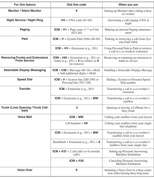
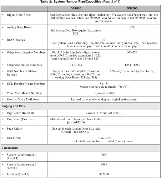
Table 2: System Number Plan/Capacities (Page 1 of 2)
DS1000 DS2000
System Options
• Classes of Service 1-15
(COS 1 normally reserved for attendants)
• Conference 32 simultaneous users in Conference (total of all Conferences system-wide) 8 simultaneous Conferences maximum
8 parties maximum in any one Conference
• Extension Hunting (ACD/ UCD) Master Numbers
8
• Extension Hunting Groups 8 (1-8)
• Group Call Pickup Groups 8 (1-8, 0 = unassigned)
• Privacy Release Groups 16 (1-16, 0 = unassigned)
• Speed Dial, Personal 20 bins at each extension (701-720)
See Speed Dial (page 481) for additional information on Speed Dial capacities.
• Speed Dial. System 10 (20-29), 100 (200-299), 1000 (2000-2999)
See Speed Dial (page 481) for additional information on Speed Dial capacities.
• Tenant Groups 1
• Timeslots Non-blocking
• Toll Restriction Levels 7 (1-7, 0 = no restriction)
Trunks
• Direct Trunk Access Codes 101-106 101-164
• Line Dial Up Codes #901-#906 #901-#964
• Ring Groups 8 (1-8)
0 = No assignment
Ring Group master numbers are normally 600-607.
• Trunk Group Access Codes 90-98
• Trunk Groups 9 (0-8)
• Trunk Ports 6 (1-6)
Trunks 4-6 require the Expansion Board. 64 (1-64)
Extensions
Charts and Illustrations
• Digital Door Boxes Each Digital Door Box uses one digital station port. The System Load Factor may limit the total number you can install. See DS2000 Load Factor on page 3 and DS1000 Load
Fac-tor on page 6.
• Analog Door Boxes 2
2nd Analog Door Box requires Expansion PCB
N/A
• DSS Consoles 4
The System Load Factor may limit the total number that you can install. See DS2000 Load Factor on page 3 and DS1000 Load Factor on page 6.
• Telephone Extension Numbers 300-333 (which includes digital exten-sions 300-315, analog extenexten-sions 31-323,
and Analog Door Boxes 324 and 325)
300-427
• Telephone Station Numbers 34 (1-34) 128 (1-128)
• Total Number of Station Devices
34 (which includes digital extensions 300-315, analog extensions 316-323, and
Analog Door Boxes 324 and 325)
128 (may be limited by load factor)
• UCD Hunting Master Numbers 8 (1-8)
Master numbers are normally 700-707.
• Voice Mail Master Numbers 1 (normally 700)
• External Voice Mail Ports Limited by available analog and digital station ports.
Paging and Park
• Page Zones (Internal) 7 zones (1-7) and All Call (0)
• Page Zone (External) All Call and zone 1 broadcast from Audio jack (AUDIO)
• Page Relays One set in each Analog Door Box jack (DOOR1 and DOOR2)
• Park Orbits 10 (60-69)
Orbits 68 and 69 have extended (5 min.) timers
Passwords
• System Administrator 1 (Level 1)
0000
• System Administrator 2 (Level 2)
9999
Table 2: System Number Plan/Capacities (Page 2 of 2)
Charts and Illustrations
1
2
3
4
5
6
7
8
9
0
ABC DEF
MW ICM
FLASH DND
DIAL MIC
LND SPK
CONF HOLD
GHI JKL MNOMNO
PQRS TUV
OPER
VOL
WXYZ
CLEAR CHECK
80000 -70
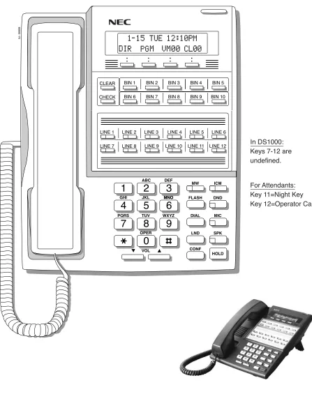
LINE 1 LINE 2 LINE 3 LINE 4 LINE 5 LINE 6 LINE 7 LINE 8 LINE 9 LINE 10 LINE 11 LINE 12 BIN 1 BIN 2 BIN 3 BIN 4 BIN 5 BIN 6 BIN 7 BIN 8 BIN 9 BIN 10
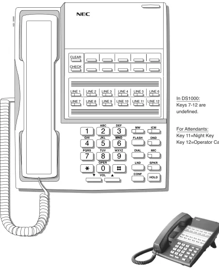
For Attendants: Key 11=Night Key
Key 12=Operator Call Key In DS1000:
Charts and Illustrations
1
2
3
4
5
6
7
8
9
0
ABC DEF
MW ICM
FLASH DND
DIAL MIC
LND SPKR
CONF HOLD
GHI JKL MNOMNO
PQRS TUV
OPER
VOL
WXYZ
CLEAR CHECK
80000 - 63A
LINE 1 LINE 2 LINE 3 LINE 4 LINE 5 LINE 6 LINE 7 LINE 8 LINE 9 LINE 10 LINE 11 LINE 12
For Attendants: Key 11=Night Key
Key 12=Operator Call Key In DS1000:
Charts and Illustrations
1
2
3
4
5
6
7
8
9
0
ABC DEF
MW ICM
FLASH DND
DIAL MIC
LND SPK
CONF HOLD
GHI JKL MNOMNO
PQRS TUV
OPER
VOL
WXYZ
CLEAR
CHECK
80000 - 72
LINE 1 LINE 2 LINE 3 LINE 4 LINE 5 LINE 6
LINE 7 LINE 8
BIN 1 BIN 2 BIN 3 BIN 4 BIN 5
BIN 6 BIN 7 BIN 8 BIN 9 BIN 10
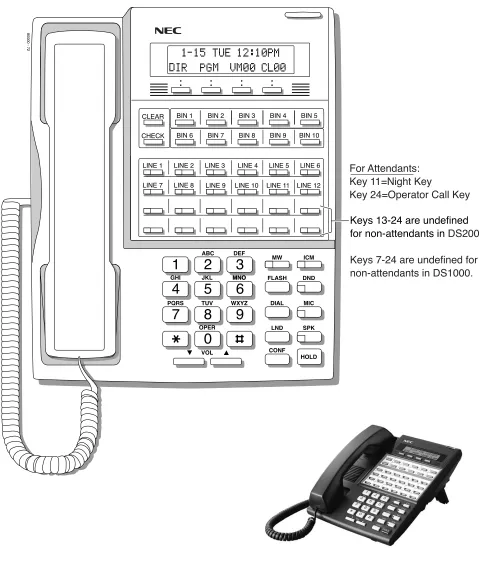
Keys 13-24 are undefined for non-attendants in DS2000.
Keys 7-24 are undefined for non-attendants in DS1000. LINE 9 LINE 10 LINE 11 LINE 12
For Attendants: Key 11=Night Key
Charts and Illustrations
1
2
3
4
5
6
7
8
9
0
ABC DEF
MW ICM
FLASH DND
DIAL MIC
LND SPKR
CONF HOLD
GHI JKL MNO
PQRS TUV
OPER
VOL
WXYZ
80000 - 71
CHECK CLEAR
LINE 1 LINE 2 LINE 3 LINE 4 LINE 5 LINE 6 LINE 7 LINE 8
Keys 13-24 are undefined for non-attendants in DS2000.
Keys 7-24 are undefined for non-attendants in DS1000.
LINE 9 LINE 10 LINE 11 LINE 12
For Attendants: Key 11=Night Key
Charts and Illustrations
80000 - 25
300 312
301 313
302 314
303 315
304 316
305 317
306 318
307 319
308 320
309 321
310 322
Charts and Illustrations
80000 - 74
300 301 302 303 304 305 306 307 308 309 310 311 312 313 314 315 316 317 318 319 320 321 322 323 324 325 326 327 328 329 330 331 332 333 334 335 336 337 338 339
350 351 352 353 354 355 356 357 358 359 360 361 362 363 364 365 366 367 368 369 370 371 372 373 374 375 376 377 378 379 380 381 382 383 384 385 386 387 388 389 390 391 392 393 394 395 PAGE 1 PAGE 2 PAGE 3 PAGEALL
Charts and Illustrations
80200 - 56
300 301 302 303 304 305 306 307 308 309 310 311 312 313 314 315 316 317 318 319 320 321 322 323 324 325 326 327 328 329 330 331 332 333
401 402
PAGE 1 PAGE 2 PAGE 3 PAGEALL
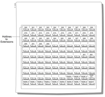
PARK 0 PARK 1 PARK 2 PARK 3 PARK 4 PARK 5 PARK 6 PARK 7 PARK 8 NIGHT Hotlines
to Extensions
2-OPX Module
2-OPX Module
Description
2500 Sets / Single Line Telephones
2500 Sets / Single Line Telephones
Description
Account Codes
Account Codes
Description
Account Codes are user-dialed codes that help categorize and/or restrict trunk calls. Account Codes are from 2-10 digits long, using any combination of the digits 0-9. There are three types of Account Codes:
● Optional (Unforced Account Codes)
● Forced Account Codes
● Verified Account Codes
Optional (Unforced) Account Codes
Optional Account Codes allow a keyset extension user to enter an Account Code while placing a trunk call or any time while on a call. This type of Account Code is optional: the system does not require the user to enter it. If the keyset user is already talking on a trunk call, their conversation continues uninterrupted while they enter an Account Code.
Single line telephone users can only enter an Account Code while placing their trunk call.
Forced Account Codes
Forced Account Codes require an extension user to enter an Account Code every time they place a trunk call. If the user doesn’t enter the code, the system prevents the call. The system can require Forced Account Codes for all trunk calls, or just for toll calls (as determined by Toll Restriction programming). Note that Forced Account Codes do not pertain to incoming calls.
Verified Account Codes
With Verified Account Codes, the system compares the Account Code the user dials with a list of codes programmed into the Verified Account Code Table. If the Account Code is in the table, the call goes through (provided it is not prevented by an extension’s Toll Restriction programming). If the code is not in the table, the system prevents the call. Verified Account Codes, if enabled, apply only to Forced Account Codes.
Using Account Codes and Speed Dial
To simplify Account Code operation, Personal and System Speed Dial bins can contain Account Codes. Keep the following in mind when using Speed Dial and Account Codes:
● The Account Code can be either the first or last entry in the bin, and must be preceded and fol-lowed by the # character. For example, the Account Code 1234 must be entered as #1234#.
● The Program 0201 - # Key to Enter Account Codes (page 629) option must be enabled in sys-tem programming. In addition, the Program 0201 - Enable Account Codes in Speed Dial (page 629) option must also be enabled.
DS1000/2000 Available.
Account Codes
● If the Speed Dial bin does not contain an Account Code, the user must enter the Account Code manually. If Forced Account Codes are enabled, the system requires the user to enter the Account Code before it outdials the stored Speed Dial number.
● An extension user can preselect a trunk for a Speed Dial call.
Using Account Codes with Last Number Redial and Save
Last Number Redial and Save do not store Account Codes. This means that the user must manually enter an Account Code to have it included with a call dialed using Last Number Redial and Save. If Forced Account Codes are enabled, the system requires the user to enter the Account Code before it outdials the stored number saved by Last Number Redial or Save.
An extension user can preselect a trunk for a Last Number Redial or Save call.
Account Codes and Emergency Calls
Account Codes are never enforced for emergency (911 and 1+911) calls.
DSS Console Account Code Key
A keyset user can have an Account Code key on their DSS Console. It works the same as a keyset Account Code key with the following exceptions:
● The DSS Console key flashes quickly red while the user is entering their Account Code. (The keyset Account Code key flashes quickly green.)
● The DSS Console key lights red while the user is on a call for which they have entered an Account Code. (The keyset Account Code key lights green.)
Conditions
Do not use Account Codes that begin with 911 or 1911.
Account Codes
Programming Guide
Step-by-step guide for setting up Account Codes (Page 1 of 3)
Step 1: Should users be able to store Account Codes in Speed Dial bins?
• In Program 0201 - Enable Account Codes in Speed Dial (page 629), enter Y.
• In Program 0201 - Enable Account Codes in Speed Dial (page 629), enter N. Any Account Codes stored in Speed Dial bins dial out as part of the stored number.
Step 2: While on an outside call, should an extension user be able to dial # to enter an Account Code?
• In Program 0201 - # Key to Enter Account Codes (page 629), enter Y.
• In Program 0201 - # Key to Enter Account Codes (page 629), enter N.
Step 3: Should Account Code entries be hidden (i.e., replaced by * characters) on each tele-phone’s display?
• In Program 0201 - View Account Codes (page 630), enter N.
• In Program 0201 - View Account Codes (page 630), enter Y.
Step 4: Should a keyset have an Account Code key to simplify entering Account Codes?
• In Program 1701 - Programmable Function Key Assignments (page 737), enter 26 to assign a key as an Account Code key.
• In Program 1701 - Programmable Function Key Assignments (page 737), do not assign a key with code 26.
If yes
If no
If yes
If no
If yes
If no
If yes
Account Codes
Step 5: Should a DSS Console have an Account Code key to simplify entering Account Codes?
• In Program 1704 - DSS Console Key Assignment (page 746), enter 26 to assign a key as an Account Code key.
• In Program 1704 - DSS Console Key Assignment (page 746), do not assign a key with code 26.
Step 6: Should an extension have Forced Account Codes (i.e., be required to enter an Account Code while placing a call)?
• In Program 0101 - Forced Account Codes (page 620), enter Y.
• Program 1801 - Extension Class of Service Assignment (page 755), assign Class of Service to extensions.
• In Program 1001 - Disable Forced Account Codes (page 703), enable No (N) to have the system enforce Forced Account Codes for the trunk. OR
In Program 1001 - Disable Forced Account Codes (page 703), enable Yes (Y) to have the system not enforce Forced Account Codes for the trunk.
• In Program 0101 - Forced Account Codes (page 620), enter N.
• Program 1801 - Extension Class of Service Assignment (page 755), assign Class of Service to extensions.
Step 7: Should an extension have Forced Account Codes just for long distance (toll) calls?
• In Program 0101 - Forced Account Codes for Toll Calls Only (page 621), enter Y.
• In Program 0201 - Account Code Toll Level (page 629), enter the toll level (0-7) the system will use to determine toll calls. See Forced Account Codes Programming on page 29 for more on setting this up.
• Program 1801 - Extension Class of Service Assignment (page 755), assign Class of Service to extensions.
Step-by-step guide for setting up Account Codes (Page 2 of 3)
If yes
If no
If yes
If no
Account Codes
Programming List
General Account Codes Programming
Program 0201 - Enable Account Codes in Speed Dial (page 629)
Enable (Y) this option if users should be able to store Account Codes in Speed Dial bins. This causes the stored Account Code to properly display in the SMDR report Account column. If you disable (N) this option, Account Codes stored in Speed Dial bins dial out as part of the stored number and display in the SMDR report Number Dialed column. They will not display in the Account column. This option is disabled by default.
Program 0201 - # Key to Enter Account Codes (page 629)
Use this option to enable (Y) an extension user to dial # to enter an Account Code while on an outside call. If disabled (N), the extension user can only enter an Account Code by pressing the Account Code soft key or a uniquely programmed Account Code Programmable Function Key. This option is disabled by default.
Program 0201 - View Account Codes (page 630)
Use this option to show or hide the Account Codes a user enters on their telephone’s display. If enabled (Y), the dialed Account Codes show on the display. This may be a security risk, since a co-worker can easily read the telephone display as the user enters their Account Code. If disabled (N), Account Codes are shown as * characters on the telephone display. This option is disabled by default.
Program 1701 - Programmable Function Key Assignments (page 737)
Use this option to assign an Account Code Programmable Function Key to a keyset (code 26). There are no Account Code Programmable Function Keys assigned by default.
Program 1704 - DSS Console Key Assignment (page 746)
Use this option to assign an Account Code Programmable Function Key to a DSS Console
Step 8: Should an extension have Verified Account Codes (i.e., be required to enter an Account Code from the Verified Account Codes Table while placing a call)?
• In Program 0101 - Verify Account Codes (page 621), enter Y.
• In Program 1201 - Verified Account Codes Table (page 721), enter codes into the Verified Account Codes table.
• In Program 1801 - Extension Class of Service Assignment (page 755), assign Class of Service to extensions.
• In Program 0101 - Verify Account Codes (page 621), enter N.
• Program 1801 - Extension Class of Service Assignment (page 755), assign Class of Service to extensions.
Step-by-step guide for setting up Account Codes (Page 3 of 3)
If yes
Account Codes
Forced Account Codes Programming
Program 0101 - Forced Account Codes (page 620)
Use this option to enable (Y) or disable (N) Forced Account Codes. If disabled, Optional Account Codes are still available. This option is disabled by default.
Program 0101 - Forced Account Codes for Toll Calls Only (page 621)
● Use this option to enable (Y) Forced Account Codes only for toll (long distance) calls. If disabled (N), Forced Account Codes apply to all outgoing trunk calls. This option is dis-abled by default (i.e., Forced Account Codes, if endis-abled, apply to all outgoing trunk calls).
● The system identifies toll calls according to the settings in Program 0201 - Account Code Toll Level (page 629) programming below.
● If Program 0101 - Forced Account Codes (page 620)is disabled, the Program 0101 - Forced Account Codes for Toll Calls Only (page 621) option has no effect.
Program 0201 - Account Code Toll Level (page 629)
If Program 0101 - Forced Account Codes for Toll Calls Only (page 621) is enabled, use this option to differentiate toll calls from local calls for Account Code purposes. If you enter 0 for this option, toll calls are any calls the user dials that begin with 0 or 1. If you enter a toll level for this option (1-7), the system uses the toll level options programmed in 0601 - Configure Toll Level Options on page 683 for that level to determine if the call is local or toll.
● If the toll level is set to deny the call, it is considered to be a long distance call and the sys-tem requires that the user must have entered an Account Code.
● If the toll level permits the call, it is considered to be a local call and no Account Code entry is required.
● Note that additional dialing restrictions enforced by an extension’s toll level (set in Pro-gram 1801 - Extension Toll Level Day (page 755) and Program 1801 - Extension Toll Level Night (page 755) are in effect and may also restrict dialing.
Program 1001 - Disable Forced Account Codes (page 703)
Use this option to enable or disable Forced Account Codes for an individual trunk. If enabled (Y), the system will not enforce Forced Account Codes for the trunk. If disabled (N), the sys-tem will enforce Forced Account Codes for the trunk.
Program 1801 - Extension Class of Service Assignment (page 755) Assign Class of Service to extensions.
Verified Account Codes Programming
Program 0101 - Verify Account Codes (page 621)
Use this option to enable (Y) or disable (N) Verified Account Codes. If enabled, the system compares the Account Code the user dials to the entries in 1201 - Verified Account Codes Table on page 721. There are no entries in this table by default.
Program 1201 - Verified Account Codes Table (page 721)
● Use this option to enter codes into the Verified Account Codes Table. When Program 0101 - Verify Account Codes (page 621) is enabled, the system compares the Account Code the user dials to the entry in this table. If the entries match, the system allows the call (pro-vided it is not prevented by an extension’s Toll Restriction). If there is no match, the sys-tem denies the call.
● A Verified Account Code can be from 1 to 10 digits long, using the digits 0-9. You can use the * character as a wild card, which can be entered in any position in a Verified Account Code. A wild card allows the user to dial any digit in that position. For example, the entry 11*1 represents entries 1101, 1111, 1121, etc.
● DS1000 provides for 500 table entries. DS2000 provides for 1000 table entries.
Account Codes
Account Codes Programming Examples
Example 1: Forced Account Codes Require an Account Code only for 900 and 1 + 900 Long Distance Dialing
To set up Forced Account Codes to require entries for only 900 and 1 + 900 calls:
1. In 0101 - Forced Account Codes, enter Y.
2. In 0101 - Forced Account Codes for Toll Calls Only, enter Y. 3. In 0201 - Account Code Toll Level, enter 2 (for example).
4. In 0601 - Initialize Toll Restriction, be sure to initialize the Toll Restriction tables. Make the following entries for Toll Restriction Level 2.
5. In 0601 - Active Dial Pad, enter Y (enabled). In 0601 - N11 Dialing, enter Y (enabled). In 0601 - 0+ Dialing, enter Y (enabled).
In 0601 - Equal Access (101X + XXX) Dialing, enter Y (enabled).
6. In 0602 - 1010 + XXX Equal Access Dialing, make a deny table with no entries (i.e., deny nothing). This is the default setting.
7. In 0603 - 1 + NPA /NXX Dialing 3-Digit Table, make a deny table and enter 900. 8. In 0604 - 1 + NPA + NXX Dialing 6-Digit Table, make a deny table with no entries (i.e.,
deny nothing). This is the default setting.
9. In 0605 - NPA/NXX Dialing 3-Digit Table, make a deny table and enter 900.
10. In 0606 - NPA + NXX Dialing 6-Digit Table, make no entries (i.e., deny nothing). This is the default setting. This table is permanently assigned as a deny table.
11. In 1801 - Extension Class of Service, assign the Class of Service with Forced Account Codes enabled to the extension.
12. In 1801 - Extension Toll Level Day and 1801 - Extension Toll Level Night, be sure the extension does not use Toll Level 2. If it does, Toll Restriction will always deny 1 + 900 and 900 calls (regardless of whether the user enters an Account Code).
An extension user can then:
1. Press a line key or dial a code for an outside line. 2. Wait for reminder tone (3 beeps).
With Forced Account Codes enabled, the system automatically goes into the Account Code mode after you press a line key in step 1 above.
If you have an Account Code Programmable Function Key, it flashes green. 3. If dialing a 1 + 900 or 900 call, dial the Account Code.
If dialing any other long distance call, skip this step.
4. Press # (if enabled), the Account Code soft key, or an Account Code Programmable Function Key (if programmed).
5. Dial the outside number.
Account Codes
Example 2: Forced Account Codes Allow 800 and 1 + 800 Long Distance Dialing Without an Account Code
To set up Forced Account Codes to require entries for all calls except 800 and 1 + 800 Dialing:
1. In 0101 - Forced Account Codes, enter Y.
2. In 0101 - Forced Account Codes for Toll Calls Only, enter Y. 3. In 0201 - Account Code Toll Level, enter 2 (for example). Make the following entries for Toll Restriction Level 2.
4. In 0601 - Active Dial Pad, enter Y (enabled). In 0601 - N11 Dialing, enter Y (enabled). In 0601 - 0+ Dialing, enter Y (enabled).
In 0601 - Equal Access (101X + XXX) Dialing, enter Y (enabled).
5. In 0602 - 1010 + XXX Equal Access Dialing, make a deny table with no entries (i.e., deny nothing). This is the default setting.
6. In 0603 - 1 + NPA /NXX Dialing 3-Digit Table, make an allow table and enter 800. 7. In 0604 - 1 + NPA + NXX Dialing 6-Digit Table, make a deny table with no entries (i.e.,
deny nothing). This is the default setting.
8. In 0605 - NPA/NXX Dialing 3-Digit Table, make an allow table and enter 800.
9. In 0606 - NPA + NXX Dialing 6-Digit Table, make no entries (i.e., deny nothing). This is the default setting. This table is permanently assigned as a deny table.
10. In 1801 - Extension Class of Service, assign the Class of Service with Forced Account Codes enabled to the extension.
An extension user can then:
1. Press a line key or dial a code for an outside line. 2. Wait for reminder tone (3 beeps).
With Forced Account Codes enabled, the system automatically goes into the Account code mode after you press a line key in step 1 above.
If you have an Account Code Programmable Function Key, it flashes green. 3. If dialing a 1 + 800 or 800 call, skip this step.
If dialing any other long distance call, dial the Account Code.
4. Press # (if enabled), the Account Code soft key, or an Account Code Programmable Function Key (if programmed).
5. Dial the outside number.
The call will go through without an Account Code. If the user doesn’t enter an Account Code for all other calls, the system will cut off the call.
Account Codes
Other Related Features
Central Office Calls, Placing (page 119)
You can use Store and Forward with Forced Account Codes. See Store and Forward with Forced Account Codes on page 120 for more.
Last Number Redial (page 351) and Save Number Dialed (page 468)
Last Number Redial and Save do not store Account Codes. This means that the user must manually enter an Account Code to have it included with a call dialed using Last Number Redial and Save.
Speed Dial (page 481)
An extension user can store an Account Code in a Speed Dial bin. See Using Account Codes and Speed Dial on page 24 for more.
Station Message Detail Recording (page 498) Account Codes print on the SMDR report.
Voice Mail (page 580)
Voice Mail callout features (such as Message Notification) may interact with Account Codes if the callout number contains # characters.
Feature Operation
To enter an Optional (Unforced) Account Code:
For keysets, Optional Account Codes apply to both incoming and outgoing calls. For outgoing calls, you can enter the Account Code before or after dialing the outside number.
For Single Line sets, Optional Account Codes apply only to outgoing calls. You must enter the Account Code after getting dial tone on the trunk but before dialing the outside number. 1. Place or answer outside call.
2. Press Account Code soft key, Programmable Function Key, or dial # (if enabled). 3. Enter Account Code (up to 10 digits long, using the digits 0-9).
4. Press Account Code soft key, Programmable Function Key, or dial # (if enabled). 5. For Outgoing Calls Only
Dial your outside number.
Toll Restriction may still prevent you from dialing certain outside numbers.
To enter a Forced Account Code:
Forced Account Codes do not apply to incoming calls. 1. Access a line for an outgoing call.
2. Enter Account Code (up to 10 digits long, using the digits 0-9).
If your system has Verified Account Codes enabled, you must enter one from the Veri-fied Account Codes Table. If you enter an invalid Verified Account Code, your call will be cut off in the next step.
3. Press Account Code soft key, Programmable Function Key, or dial # (if enabled). Three beeps.
Alphanumeric Display
Alphanumeric Display
Description
The 22- and 34-Button Display Telephones have a two-line, 20-character per line alphanumeric dis-play. The first line displays the date and time (while idle) and feature status messages. The second line displays the Soft Key definitions.
The 34-Button Super Display Telephone has an eight-line, 20-character per line alphanumeric dis-play. The first line displays the date and time (while idle) and feature status messages, just like the 22- and 34-Button Display Telephones. Lines 2-8 are the comprehensive Super Display Telephone soft key definitions.
● To learn more about the display telephones: - see 22-Button Display Telephone on page 15 - see 34-Button Display Telephone on page 17 - see 34-Button Super Display Telephone on page 18
● To learn more about the Soft Keys, see Soft Keys on page 480.
Conditions None
Default Setting
Enabled for all display telephones.
Programming Guide
NoneProgramming List
NoneOther Related Features
Soft Keys (page 480)The interactive Soft keys provide users with intuitive access to the telephone’s features.
Volume Controls (page 603)
While a feature is active, pressing VOL ▲ and VOL ▼ adjusts the volume of the active feature. While a 22-Button or 34-Button Display telephone is idle, pressing VOL ▲ and VOL ▼
DS1000/2000 Available.