ISSN 22773061
Performance Comparison of PI and Fuzzy-PI Logic Speed Control of
Induction Motor
Darshan Singh
1Dalveer Kaur
2Yaduvir Singh
31
Department of Electronics and Communication Engineering, GZSCET Bhatinda, Punjab
2
Punjab Technical University, Kapurthala Road, Jallandhar
3
Noida Institute of Engineering and Technology, Greater Noida, Uttar Pradesh
1
Corresponding author Email ID: [email protected]
Abstract
Single-phase induction motors are also used extensively for smaller loads. Speed control of induction motor has been implemented using PI (Proportional-Integral) controller and Fuzzy PI controller in Simulink MATLAB. The results show that induction motor Fuzzy-PI speed control method results in a quicker response with no overshoot than the conventional PI controller. The settling time of induction motor Fuzzy-PI speed is better than the conventional PI controller. The integral time of weighted absolute error (ITEA) performance criteria also shows that the induction motor Fuzzy-PI speed control has better performance. Moreover, the induction motor Fuzzy-PI speed control has a strong ability to adapt to the significant change of system parameters.
Keywords: PID Controller, Shell and tube heat exchanger, Hybrid fuzzy controller
Council for Innovative Research
Peer Review Research Publishing System
Journal
:
INTERNATIONAL JOURNAL OF COMPUTERS & TECHNOLOGY
Vol 6, No 3
I. ntroduction
An induction or asynchronous motor is an AC motor in which all electromagnetic energy is transferred by inductive coupling from a primary winding to a secondary winding, the two windings being separated by an air gap. In three-phase induction motors, that are inherently self-starting, energy transfer is usually from the stator to either a wound rotor or a short-circuited squirrel cage rotor. Three-phase cage rotor induction motors are widely used in industrial drives because they are rugged, reliable and economical. Single-phase induction motors are also used extensively for smaller loads. Although most AC motors have long been used in fixed-speed load drive service, they are increasingly being used in variable-frequency drive (VFD) service, variable-torque centrifugal fan, pump and compressor loads being by far the most important energy saving applications for VFD service. Squirrel cage induction motors are most commonly used in both fixed-speed and VFD applications. Usage of induction motors reminds us to develop a better control over it. This induction motors have the advantage of decoupling (separation) of the torque and flux control which makes high servo quality achievable. [17, 22, 30] Torque and flux parameters are responsible for generating rotating motion of rotor. These parameters are affected depending on the load disturbances. The decoupling control feature can be adversely affected by load torque disturbances and parameter variations in the motor. This instantly lowers the speed down compared to the desired speed so that the variable-speed tracking performance of an Induction motor is degraded. In order to attain the rated speed there are many controllers like conventional PI controller. A proportional-integral controller (PI controller) is a generic control loop feedback mechanism (controller) widely used in industrial control systems. A PI controller calculates an "error" value as the difference between a measured process variable and a desired set point. The controller attempts to minimize the error by adjusting the process control inputs. [1-8] The PI controller calculation (algorithm) involves three separate constant parameters, and is accordingly sometimes called three-term control: the proportional, the integral and derivative values, denoted P and I. Heuristically, these values can be interpreted in terms of time: P depends on the present error, I on the accumulation of past errors, and derivation is a prediction of future errors, based on current rate of change. The weighted sum of these three actions is used to adjust the process via a control element such as the position of a control valve, a damper, or the power supplied to a heating element. In the absence of knowledge of the underlying process, a PI controller has historically been considered to be the best controller. By tuning the three parameters in the PI controller algorithm, the controller can provide control action designed for specific process requirements. The response of the controller can be described in terms of the responsiveness of the controller to an error, the degree to which the controller overshoots the set point and the degree of system oscillation. Note that the use of the PI algorithm for control does not guarantee optimal control of the system or system stability [9, 22, 25-29]. But, these have the difficulty in making the motor closely follow a reference speed trajectory under torque disturbances. In this regard, an effective and robust speed controller design is needed. The emerging of artificial intelligence soft computing techniques for finding any difficult solution became a source for developing new technologies in several applications. One of those computing techniques is fuzzy-logic. Fuzzy logic is a form of many-valued logic or probabilistic logic; it deals with reasoning that is approximate rather than fixed and exact. Compared to traditional binary sets (where variables may take on true or false values) fuzzy logic variables may have a truth value that ranges in degree between 0 and 1. Fuzzy logic has been extended to handle the concept of partial truth, where the truth value may range between completely true and completely false. Furthermore, when linguistic variables are used, these degrees may be managed by specific functions. The term "fuzzy logic" was introduced with the 1965 proposal of fuzzy set theory by Lotfi A. Zadeh. Fuzzy logic has been applied to many fields, from control theory to artificial intelligence. Fuzzy logics however had been studied since the 1920s as infinite-valued logics notably by Łukasiewicz and Tarski; it is a popular misconception that they were invented by Zadeh. These are referred as intelligent controllers which we have been proposed for speed control of induction motor. Thos controllers are associated with adaptive gains due to fuzzy inference and knowledge base. As a result, they can improve torque disturbance rejections in comparison with best trial-and-error PI controllers. Nonetheless, no performance advantages of intelligent controllers in combination with a PI controller are investigated. Motivated by the successful development and application we propose a hybrid PI + Fuzzy controller consisting of a PI controller and a fuzzy logic controller (FLC) in a serial arrangement for speed control of induction motor more specifically, direct field-oriented induction motor drives. The Ziegler-Nichols (Z-N)) method is adopted for designing a PI controller because its design rule is simple and systematic. We next design a FLC carrying out fuzzy tuning of the output of the Z-N PI controller to issue adequate torque commands. The results show that the incorporation of the proposed controller into the DFOIM drives can yield superior and robust variable speed tracking performance [2, 3, 7, 33].
II. Case Study: Speed Control of Induction Motor
Induction motors (IM) have long been widely used in many industrial applications. IM can be considered as a single input, single output (SISO) system having torque-speed characteristics compatible with most mechanical loads. This makes a IM controllable over a wide range of speeds by using appropriate control methods. Mathematical modelling is one of the most important and often difficult steps towards understanding a physical system. In everyday life, most of the observed phenomena have dynamic components. The aim of IM modelling is to find the governing differential equation that relates the applied voltage with the produced torque or speed of the rotor. The second part of the modelling is to determine the parameters of the model. All procedures of control methods need the knowledge of a system mathematical model. Any deviation between the parameters real values and those belonging to any electrical apparatus induces the control performances deterioration. Hence it is indispensible to use a high performance method to identify the IM parameters. It is used to identify the IM parameters values in industrial control. Identification of an unknown dynamic system can be defined
as an experimental process of building a mathematical model belonging to a class of models presented which reflects precisely its behaviour. Considering the referred objective and accuracy, the candidate model will satisfy in an equivalent manner the process to identify, when submitted to the same constraints leading to the definition of the identification method. The conventional control methods of induction motor (IM) have various drawbacks, such as; (i) If mathematical model of the system is not accurate, it is not possible to get accurate results, (ii) Load disturbance, motor saturation and thermal variations affect motor performance adversely, (iii) Classical linear control shows good performance only at one operating speed.
Further, to implement conventional control, the model of the controlled system should be known. The usual method of computation of mathematical model of a system is difficult. When there are system parameter variations or environmental disturbance, the behaviour of the system is not satisfactory. The induction motor modelled, controlled and simulated in this work has following parameters. [18, 20, 32]
Parameters
Values
Stator resistance
0.087 ohm
Stator inductance
0.8 µH
Rotor resistance
0.228 ohm
Rotor inductance
0.8 µH
Mutual inductance
34.7 mH
Inertia
1.662 kg.m
2Friction factor
0.1 N.m.s
Pole pairs
2
The general construction of induction motor consists of a stator, a rotor and stator winding. The stator consists of a series of wire windings of very low resistance permanently attached to the motor frame.
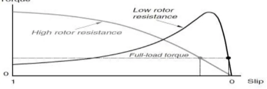
In the construction of rotor there are two types of windings essentially viz. squirrel-cage windings, which produce a squirrel-cage induction motor (most common) and conventional 3-phase windings made of insulated wire, which produce a wound-rotor induction motor (special characteristics). Figure 1 shows the characteristics curve of the induction motor between torque and speed.
Figure 1: Characteristics curve of the induction motor
The rotor is comprised of a number of thin bars, usually Aluminium, mounted in a laminated cylinder. The bars are arranged horizontally and almost parallel to the rotor shaft. At the ends of the rotor, the bars are connected together with a ―shorting ring.‖ The rotor and stator are separated by an air gap which allows free rotation of the rotor. Figure 2 shows the equivalent circuit of the induction motor. [4,13, 31]
Figure 2: Equivalent Circuit of Induction motor
The physical relationship between the variables to be considered can be found working from the induction motor stator circuit equation in the stator frame of reference Eq. (1);
If flux orientation is such that then the flux dynamic amplitude will be given by the real part of Eq. (2) as follows:
(2)
Hence, the direct component of the stator voltage vector directly controls the stator flux. In this conditions torque is a function of the stator current sq component:
(3)
From Eq. (2) and (3):
(4)
Hence, the stator vector sq component can be used for torque control, with an adequate decoupling between the flux and torque control functions. It is necessary then to use the flux errors as inputs to the PI controllers that will determine the direct and sq components of the new stator voltage vector. To increase the system information level, the flux space vector rotational speed is calculated as the time derivative of the flux space vector position. This can be used to give an element of acceleration to the calculation of sq voltage vector component, increasing the torque controller robustness. [10, 18, 25, 31]
III. Problem Formulation
Here, in this work, speed control of induction motor has been done with the help of PI controller and Fuzzy Logic Controller.
PI speed control
A proportional–integral–derivative controller (PI controller) is a generic control loop feedback mechanism widely used in industrial control systems – a PI is the most commonly used feedback controller. A PI controller calculates an "error" value as the difference between a measured process variable and a desired set point. The controller attempts to minimize the error by adjusting the process control inputs. In the absence of knowledge of the underlying process, PI controllers are the best controllers. However, for best performance, the PI parameters used in the calculation must be tuned according to the nature of the system – while the design is generic, the parameters depend on the specific system. The PI controller calculation involves three separate parameters, and is accordingly sometimes called three-term control: the proportional, the integral and derivative values, denoted P, I, and D. The proportional value determines the reaction to the current error, the integral value determines the reaction based on the sum of recent errors, and the derivative value determines the reaction based on the rate at which the error has been changing. The weighted sum of these three actions is used to adjust the process via a control element such as the position of a control valve or the power supply of a heating element. Heuristically, these values can be interpreted in terms of time: P depends on the present error, I on the accumulation of past errors, and D is a prediction of future errors, based on current rate of change. By tuning the three constants in the PI controller algorithm, the controller can provide control action designed for specific process requirements. The response of the controller can be described in terms of the responsiveness of the controller to an error, the degree to which the controller overshoots the setpoint and the degree of system oscillation. Note that the use of the PID algorithm for control does not guarantee optimal control of the system or system stability. The PID controller is probably the most-used feedback control design. PID is an acronym for Proportional-Integral-Derivative, referring to the three terms operating on the error signal to produce a control signal. If u(t) is the control signal sent to the system, y(t) is the measured output and r(t) is the desired output, and tracking error e(t) = r(t) − y(t), a PID controller has the general form.
( )
P( )
I( )
Dd
( )
u t
K e t
K
e t dt
K
e t
dx
(5)
The desired closed loop dynamics is obtained by adjusting the three parameters KP, KI and KD, often iteratively by "tuning" and without specific knowledge of a plant model. Stability can often be ensured using only the proportional term. The integral term permits the rejection of a step disturbance. The derivative term is used to provide damping or shaping of the response. PID controllers are the most well established class of control systems: however, they cannot be used in several more complicated cases, especially if MIMO systems are considered. Applying Laplace transformation results in the transformed PI controller equation
1
( )
P( )
I( )
D( )
u s
K e s
K
e s
K se s
s
(6)With the PID control transfer function
1
( )
P I DC s
K
K
K s
s
(7)The proportional term (sometimes called gain) makes a change to the output that is proportional to the current error value. The proportional response can be adjusted by multiplying the error by a constant Kp, called the proportional gain. The proportional term is given by:
Pout=Kp e(t) (8)
Here, Pout is Proportional term of output, Kp Proportional gain, a tuning parameter, e (Error) = SP – PV and t the time or instantaneous time (the present)
A high proportional gain results in a large change in the output for a given change in the error. If the proportional gain is too high, the system can become unstable. In contrast, a small gain results in a small output response to a large input error, and a less responsive or sensitive controller. If the proportional gain is too low, the control action may be too small when responding to system disturbances. In the absence of disturbances, pure proportional control will not settle at its target value, but will retain a steady state error that is a function of the proportional gain and the process gain.
The contribution from the integral term sometimes called reset is proportional to both the magnitude of the error and the duration of the error. Summing the instantaneous error over time gives the accumulated offset that should have been corrected previously. The accumulated error is then multiplied by the integral gain and added to the controller output. The magnitude of the contribution of the integral term to the overall control action is determined by the integral gain, Ki. The integral term is given by:
( )
out I
I
K
e t dt
(9)
Here, Iout is Integral term of output, KI: Integral gain, a tuning parameter, e: (Error) = SP – PV, t: Time or instantaneous time (the present) and τ: a dummy integration variable
The integral term when added to the proportional term accelerates the movement of the process towards set point and eliminates the residual steady-state error that occurs with a proportional only controller. However, since the integral term is responding to accumulated errors from the past, it can cause the present value to overshoot the set point value.
The rate of change of the process error is calculated by determining the slope of the error over time i.e., its first derivative with respect to time and multiplying this rate of change by the derivative gain Kd. The magnitude of the contribution of the derivative term to the overall control action is termed the derivative gain, Kd. The derivative term is given by:
( )
out Dd
D
K
e t
dx
(10)Here, Dout is Derivative term of output, KD: Derivative gain, a tuning parameter, e (Error) = SP − PV and t: Time or instantaneous time (the present)
The derivative term slows the rate of change of the controller output and this effect is most noticeable close to the controller setpoint. Hence, derivative control is used to reduce the magnitude of the overshoot produced by the integral component and improve the combined controller-process stability. However, differentiation of a signal amplifies noise and thus this term in the controller is highly sensitive to noise in the error term, and can cause a process to become unstable if the noise and the derivative gain are sufficiently large. Hence an approximation to a differentiator with a limited bandwidth is more commonly used. Such a circuit is known as a Phase-Lead compensator.
The proportional, integral, and derivative terms are summed to calculate the output of the PID controller. Defining u(t) as the controller output, the final form of the PID algorithm is:
0
( )
( )
p( )
i t( )
d( )
d
u t
MV t
K e t
K
e t dt
K
e t
dx
(11)Here, the tuning parameters are of three types viz. Proportional gain (Kp), Integral gain (Ki) and Derivative gain (Kd) Larger values of Proportional gain (Kp) typically mean faster response since the larger the error, the larger the proportional term compensation. An excessively large proportional gain will lead to process instability and oscillation. Larger values of Integral gain (Ki) imply steady state errors are eliminated more quickly. The trade-off is larger overshoot: any negative error integrated during transient response must be integrated away by positive error before reaching steady state. Larger values of Derivative gain (Kd) decrease overshoot, but slow down transient response and may lead to instability due to signal noise amplification in the differentiation of the error.
Tuning a control loop is the adjustment of its control parameters i.e. gain/proportional band, integral gain/reset, derivative gain/rate to the optimum values for the desired control response. Stability is a basic requirement, but beyond that, different systems have different behavior, different applications have different requirements, and some desiderata conflict. Further, some processes have a degree of non-linearity and so parameters that work well at full-load conditions don't work when the process is starting up from no load; this can be corrected by gain scheduling. PID controllers often provide acceptable control even in the absence of tuning, but performance can generally be improved by careful tuning, and performance may be unacceptable with poor tuning. PID tuning is a difficult problem, even though there are only three parameters and in principle is simple to describe, because it must satisfy complex criteria within the limitations of PID
control. There are accordingly various methods for loop tuning, and more sophisticated techniques are the subject of patents; this section describes some traditional manual methods for loop tuning.
If the PID controller parameters are chosen incorrectly, the controlled process input can be unstable, i.e. its output diverges, with or without oscillation, and is limited only by saturation or mechanical breakage. Instability is caused by excess gain, particularly in the presence of significant lag. Generally, stability of response is required and the process must not oscillate for any combination of process conditions and set points, though sometimes marginal stability is acceptable or desired.
The optimum behavior on a process change or set point change varies depending on the application. Two basic desiderata are regulation and command tracking these refers to how well the controlled variable tracks the desired value. Specific criteria for command tracking include rise time and settling time. Some processes must not allow an overshoot of the process variable beyond the setpoint if, for example, this would be unsafe. Other processes must minimize the energy expended in reaching a new set point.
There are several methods for tuning a PI loop. The most effective methods generally involve the development of some form of process model, then choosing P and I based on the dynamic model parameters. Manual tuning methods can be relatively inefficient, particularly if the loops have response times on the order of minutes or longer. The choice of method will depend largely on whether or not the loop can be taken "offline" for tuning, and the response time of the system. If the system can be taken offline, the best tuning method often involves subjecting the system to a step change in input, measuring the output as a function of time, and using this response to determine the control parameters.
If the system must remain online, one tuning method is to first set Ki and Kd values to zero. Increase the Kp until the output of the loop oscillates, then the Kp should be set to approximately half of that value for a "quarter amplitude decay" type response. Then increase Ki until any offset is correct in sufficient time for the process. However, too much Ki will cause instability. Finally, increase Kd, if required, until the loop is acceptably quick to reach its reference after a load disturbance. However, too much Kd will cause excessive response and overshoot. A fast PI loop tuning usually overshoots slightly to reach the setpoint more quickly; however, some systems cannot accept overshoot, in which case an over-damped closed-loop system is required, which will require a Kp setting significantly less than half that of the Kp setting causing oscillation.
Table 1: Effects of increasing a parameter independently
Parameter Rise Time Overshoot Settling Time Steady-State Error
Stability
KP Decrease Increase Decrease Decrease Degrade KI Decrease Increase Decrease Decrease
Significantly Degrade KD Minor Decrease Minor Decrease Minor Decrease No effect in theory Improve if KD small
Another heuristic tuning method is formally known as the Ziegler–Nichols method, introduced by John G. Ziegler and Nathaniel B. Nichols. As in the method above, the Ki and Kd gains are first set to zero. The P gain is increased until it reaches the ultimate gain, Ku, at which the output of the loop starts to oscillate. Ku and the oscillation period Pu are used to set the gains as shown.
Table 2: Ziegler–Nichols method
Control Type KP KI KD
P 0.50Ku --- ----
PI 0.45Ku 1.2Kp/Pu ----
PID 0.60Ku 2Kp/Pu KpPu/8
The closed – loop Ziegler-Nichols method consist of following steps.
1. With P-only closed loop control, increase the magnitude of the proportional gain until the closed loop is in a continuous oscillation. For slightly larger values of controller gain, the closed loop system is unstable, while the slightly lower values the system is stable.
2. The value of controller proportional gain that causes the continuous oscillation is called the critical gain, Ku. The peak- to - peak period is called critical period Pu.
3. Depending upon controller chosen, P or PI, use the value in table 2 for tuning parameters based on the critical gain and period.
Fuzzy Logic speed Control
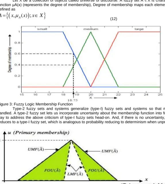
Fuzzy logic requires some numerical parameters in order to operate such as what is considered significant error and significant rate-of-change-of-error, but exact values of these numbers are usually not critical unless very responsive performance is required in which case empirical tuning would determine them. There are two types of fuzzy set viz. Type I Fuzzy Set and Type II Fuzzy Set.
Let X be a collection of objects called universe of discourse. A fuzzy set A X is characterized by membership function μA(x) (represents the degree of membership), Degree of membership maps each element between 0 and 1. It is defined as
,
A( ) ;
A
x
x
x
X
(12)
Figure 3: Fuzzy Logic Membership Function
Type-2 fuzzy sets and systems generalize (type-I) fuzzy sets and systems so that more uncertainty can be handled. A type-2 fuzzy set lets us incorporate uncertainty about the membership function into fuzzy set theory, and is a way to address the above criticism of type-I fuzzy sets head-on. And, if there is no uncertainty, then a type-II fuzzy set reduces to a type-I fuzzy set, which is analogous to probability reducing to determinism when unpredictability vanishes.
Figure 4: FOU for an interval type-2 fuzzy set.
The membership function of a general type-II fuzzy set, Ã, is three-dimensional (Figure 4), where the third dimension is the value of the membership function at each point on its two-dimensional domain that is called its footprint of uncertainty (FOU). Fuzzy inference systems (FIS) are rule-based systems. It is based on fuzzy set theory and fuzzy logic. FIS are mappings from an input space to an output space. FIS allows constructing structures which are used to generate output responses for certain stimulations. Response of FIS is based on stored knowledge. Knowledge is stored in the form of a rule base. Rule base is a set of rules. Rule base expresses relations between inputs of system and its expected outputs. Knowledge is obtained by eliciting information from specialists. These systems are usually known as fuzzy expert systems. Another common denomination for FIS is fuzzy knowledge-based systems. It is also called as data-driven fuzzy systems. FIS are usually divided in two categories viz. multiple input and multiple output (MIMO) systems and Multiple Input and Single Output (MISO) systems, the system returns several outputs based on the inputs which it receives. Multiple input and single output (MISO) systems are those where only one output is returned from multiple inputs. MIMO systems are decomposed into a set of MISO systems which work in parallel. In terms of inference process there are two main classes of FIS viz. Mamdani-type FIS and Takagi-Sugeno- Kang (TSK) type FIS.
Figure 5: Fuzzy inference system
In mamdani based fuzzy inference system, inputs and output have an If-Then rules. A typical rule in a sugeno fuzzy model is: IF X is Negative Big AND Y is Negative Small THEN Z is Zero. Sugeno-type systems are used to model any inference system in which output membership functions are either linear or constant. This fuzzy inference system was introduced in 1985. It is also called as Takagi-Sugeno-Kang. Sugeno output membership functions (z) are either linear or constant. A typical rule in a Sugeno fuzzy model is If Input 1 = x and Input 2 = y, then Output is z = ax + by + c For a zero-order Sugeno model, the output level z is a constant (a=b =0). Both Sugeno and Mamdani FIS can be used to perform the similar tasks. Rule base and fuzzification remain same for the variables. There are various defuzzifiers that can be chosen for a Mamdani FIS. These defuzzifiers also originate similar results in a Sugeno FIS. There is a certain overlap between both types of systems. Mamdani FIS is more widely used. It is used for decision support applications, because its intuitive and interpretable nature. Consequents of the rules in a Sugeno FIS do not have a direct semantic mean. This means that they are not linguistic terms. Also, this interpretability is partially lost. Sugeno FIS rules consequents can have many parameters per rule as per input values. Thus, Sugeno FIS gets translated into more degrees of freedom in its design as compared to Mamdani FIS. Thus it provides more flexibility. Many parameters can be used in the consequents of the rules of a Sugeno FIS. A zero order Sugeno FIS can reasonably approximate a Mamdani FIS. In computational terms, a Sugeno FIS is more efficient than a Mamdani FIS. It is so because; Sugeno FIS does not involve computationally expensive defuzzification process. Also, a Sugeno FIS always generates continuous surfaces. The continuity of the output surface is quite important. Any existence of discontinuities will result in similar inputs originating substantially different outputs. It will be a situation which is undesirable from the control monitoring perspective. Because of continuous structure of output functions, a Sugeno FIS is also better and adequate for functional analysis than a Mamdani FIS.
Figure 6: Fuzzy Rule Base in the case of a Mamdani Fuzzy Inference System
Defuzzification is a process in which fuzzy output converts back to crisp values. There are different types defuzzification methods given as
Max Membership
c( *)
z
c( )
z
for allz
Z
(13)Centroid *
( ).
( )
c cz zdz
z
z dz
(14) Weighted average *( ).
( )
c cz z
z
z
(15) Mean-Max *2
a
b
z
(16) Center of Sum 1 * 1*
( )
( )
n c k z n c k zz
z dz
z
z dz
(17)Center of Largest Area
*
( )
( )
c cz zdz
z
z dz
(18)In classical control scheme we have open loop and closed loop control architecture. Figure 8 shows the classical feedback control structure of a plant. In fuzzy control scheme the conventional controller is replaced by fuzzy logic controller.
Figure 8: Classical Feedback Control Structure
The majority of fuzzy logic control systems are knowledge-based systems in that either their fuzzy models or their fuzzy logic controllers are described by fuzzy IF-THEN rules, which have to be established based on experts‘ knowledge about the systems, controllers, performance, etc. Moreover, the introduction of input-output intervals and membership functions is more or less subjective, depending on the designer‘s experience and the available information. However, we emphasize once again that after the determination of the fuzzy sets, all mathematics to follow are rigorous. Also, the purpose of designing and applying fuzzy logic control systems is, above all, to tackle those vague, ill-described, and complex plants and processes that can hardly be handled by classical systems theory, classical control techniques, and classical two-valued logic. This is the first type of fuzzy logic control system: the fuzzy logic controller directly performs the control actions and thus completely replaces a conventional control algorithm. Yet, there is another type of fuzzy logic control system: the fuzzy logic controller is involved in a conventional control system and thus becomes part of the mixed control algorithm, so far as to enhance or improve the performance of the overall control system.
The fuzzy logic controller provides an algorithm, which converts the expert knowledge into an automatic control strategy. Fuzzy logic is capable of handling approximate information in a systematic way and therefore it is suited for controlling non linear systems and is used for modeling complex systems, where an inexact model exists or systems where ambiguity or vagueness is common. The fuzzy control systems are rule-based systems in which a set of fuzzy rules represent a control decision mechanism for adjusting the effects of certain system stimuli. With an effective rule base, the fuzzy control systems can replace a skilled human operator. The rule base reflects the human expert knowledge, expressed as linguistic variables, while the membership functions represent expert interpretation of those variables.
Figure 9: Fuzzy Logic Control Structure
Designing a good fuzzy rule base is the key to obtain satisfactory control performance. Classical analysis and control strategy are incorporated in the rule base. At last defuzzified output is obtained.
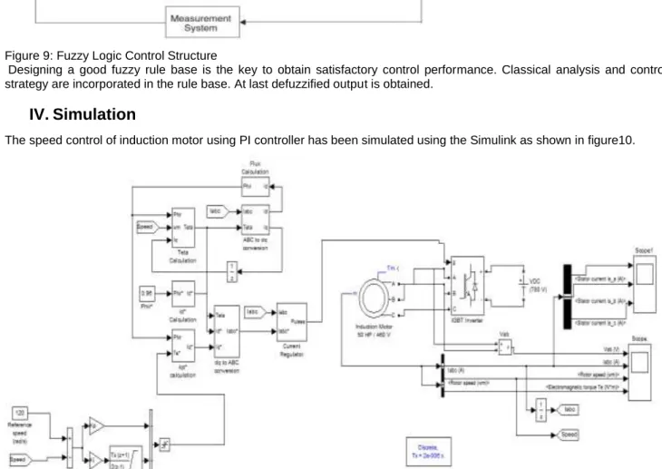
IV. Simulation
The speed control of induction motor using PI controller has been simulated using the Simulink as shown in figure10.
Figure 10: Simulink MATLAB model for Conventional PI controller
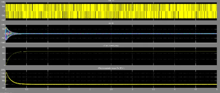
The simulation results of speed control of induction motor using PI controller using the Simulink MATLAB are shown in figure 11.
Figure 11: Simulation results of speed control of induction motor using PI controller using the Simulink MATLAB
The speed control of induction motor using Fuzzy-PI controller has been simulated using the Simulink as shown in figure12.
Figure 12: Simulink MATLAB model for Fuzzy-PI
The simulation results of speed control of induction motor using Fuzzy-PI controller using the Simulink MATLAB are shown in figure 13.
Figure 13: Simulation results of speed control of induction motor using Fuzzy-PI controller using the Simulink MATLAB
V. Results and Discussion
The time response from simulation results of speed control of induction motor using PI and Fuzzy-PI controller using the Simulink MATLAB are shown in figure 14.
Figure 14: Time response graphs from simulation results of speed control of induction motor
using PI and Fuzzy-PI controller
The response curves as shown in the figure 14 elicit that the Fuzzy PI response is better as it is getting settled fast. Table 3: Parameters comparison between PI and Fuzzy PI speed control of induction motor
Parameters Conventional PI Fuzzy PI
Peak overshoot 28.4805 0
Settling time 2.0311 0.3234
As shown in table 3 the Fuzzy PI control has clear edge over the conventional PI control of the speed control of the induction motor. There is a significant reduction in all the times response performance indices as mentioned in this table 3. Table 4: Error criterion calculation and comparison between PI and Fuzzy PI speed control of induction motor
Error criterion Conventional PI Fuzzy PI
IE 12.38 15
IAE 74.47 15
ISE 4066 826.2
ITAE 58.34 6.055
As shown in table 4 the Fuzzy PI control has clear edge over the conventional PI control of the speed control of the induction motor. There is a significant reduction in error as given by various error criteria as mentioned in this table 4.
VI. Conclusions
Matlab simulations results show that induction motor Fuzzy-PI speed control method results in a quicker response with no overshoot than the conventional PI controller. The settling time of induction motor Fuzzy-PI speed is better than the conventional PI controller. The integral time of weighted absolute error (ITEA) performance criteria also shows that the induction motor Fuzzy-PI speed control has better performance. Moreover, the induction motor Fuzzy-PI speed control has a strong ability to adapt to the significant change of system parameters. The peak time, settling time, peak overshoot, IE, IAE, ISE and ITEA criteria of different control method for induction motor speed control are shown in tables 3 and 4. As a future scope to this work for adaptive and optimal speed control of induction motor, neural networks, genetic algorithms or particle swarm optimization can also be used to improve the control efficiency.
VII.
References
[1] M. S. Adler, K. W. Owyang, B Jayanl Baliga, and R. A. Kokosa, "The Evolution of Power Device Technology," IEEE Transactions on Electron DevicesVol. ED-31,No.11, Nov. 1984,pp.1570-1591.
[2] R. L. Avant and F. C. Lee, "A Unified SCR Model for Continuous Topology CADA,"IEEE Transactions or Industrial Electronics, Vol. IE-31, No.4, Nov. 1984, pp. 352-361.
[3] GCD Sonsa and BK Bose, "A Fuzzy set theory based control of a phase control converter DC Machine drive", IEEE transactions on Industry Application vol.30. pp. 38, Jan- Feb 1994
[4] Jinwoo Kim, Yoonkeon Moon, and Bernard P. Zeigler, "Designing Fuzzy net controllers using Type II fuzzy logic", IEEE control systems, pp.66- 72, 1995
[5] Gazdik, ―Fault detector and prevention by fuzzy sets,‖ IEEE Trans. Rel., vol. R-34, pp. 382–388, Oct. 1985.
[6] ―Engine fault analysis part II: Parameter estimation approach,‖ IEEE Trans. Ind. Electron., vol. 32, pp. 301–307, Nov. 1985.
[7]. S. R. Chu, R. Shoureshi, and M. Tenorio, ―Neural networks for system identification,‖ IEEE Contr. Syst. Mag., vol. 10, pp. 31–35, Apr. 1990.
[8] I.Alguindigue, A. L. Buczak, and R. E. Ulrig, ―Monitoring and diagnosing element bearing faults using neural networks,‖ IEEE Trans. Ind. Electron., vol. 40, pp. 209–217, Apr. 1993.
[9] M. Y. Chow, R. N. Sharpe, and J. C. Hung, ―On the application and design of artificial neural networks for motor fault detection—Part 1,‖ IEEE Trans. Ind. Electron., vol. 40, pp. 181–188, Apr. 1993.
[10] J. R. Jang, ―ANFIS: Adaptive-network-based fuzzy inference system,‖ IEEE Trans. Syst., Man, Cybern., vol. 23, pp. 665–685, May/June 1993.
[11] C. Li and C.-H. Wu, ―Automatically generated rules and membership functions for a neural fuzzy-based fault classifier,‖ in Proc. Midwest Symp. Circuits and Systems, 1994, vol. 2, pp. 1377–1380.
[12] R. N. Sharpe, M. Y. Chow, S. Briggs, and L. Windigland, ―Methodology using fuzzy logic to optimize feed forward artificial neural network configurations,‖ IEEE Trans. Syst., Man, Cybern., vol. 24, pp. 760–767, May 1994.
[13] P. V. Goode and M. Y. Chow, ―Using a neural/fuzzy system to extract heuristic knowledge of incipient faults in induction motors: Part II—Application,‖ IEEE Trans. Ind. Electron., vol. 42, pp. 139–146, Apr. 1995.
[14] J. R. Jang and C. T. Sun, ―Neuro-fuzzy modeling and control,‖ Proc. IEEE, vol. 83, pp. 378–406, Mar. 1995.
[15] F. Filipetti, G. Franchescini, and C. Tassoni, ―Neural networks aided online diagnostics of induction motor faults,‖ IEEE Trans. Ind. Applicat., vol. 31, pp. 892–899, July/Aug. 1995.
[16] M. K. Mishra, S.G. Tarnekar, D. P. Kothari, Arindam Ghosh ―Detection of incipient faults in single phase Induction motors using Fuzzy logic; ―Proceedings of IEEE International Conference on Power Electronics, Drives and Energy systems for Industrial Growth, New Delhi, January 1996‖, pp. 117-121
[17] Andrew J Barr and Dr. Jeffrey L.Ray , "Control of an active suspension using Type I fuzzy logic", Proceedings of the fifth IEEE international conference on fuzzy systems, vol.l, 8-11, Sep 1996
[18] D.S. Yeung and ECC. Tsang, "A multilevel weighted Fuzzy reasoning Algorithm for expert system", IEEE transactions on systems, Man and Cybernetics, vol.28, No.2. pp. 149-158, Mar 1998
[19] Gyuiseppe Ascia and Vincenzo catania, "A High performance processor for applications based on Type I fuzzy logic", IEEE international Fuzzy systems conference proceedings, Aug 22-25,1999
[20] Angelov, P. and Buswell, R. ―Identification of evolving fuzzy rule-based models‖ IEEE Transactions on Fuzzy Systems, Vol.10, Issue 5, pp.667-677, Oct.. 2002
[21] Foulloy, L. and Galichet, S., ―Fuzzy control with fuzzy inputs‖ IEEE Transactions on Fuzzy Systems, Vol.11, Issue 4, pp.437-449, August 2003
[22] Baranyi, P. Koczy, L.T. and Gedeon, T.D., ―A Generalized Concept for Fuzzy Rule Interpolation‖ IEEE Transactions on Fuzzy Systems, Vol.12, Issue 6, pp. 820-837, Dec. 2004
[23] Park, Y., Tahk, M.-J. and Bang, H., ―Design and Analysis of Optimal Controlfor Fuzzy Systems With Input Constraint‖ IEEE Transactions on Fuzzy Systems, Vol.12, Issue 6, pp. 766-779, Dec. 2004
[24] Li, Y. and Li, S., ―A Fuzzy Sets Theoretic Approach to Approximate Spatial Reasoning‖, IEEE Transactions on Fuzzy Systems, Vol.12, Issue 6, pp. 745-754, Dec. 2004
[25] Singh G.K., ―A Research Survey of Induction Motor Operation with Non-Sinusoidal Supply Waveforms‖, Electric Power System Research, USA, Vol.75, No.2, Aug 2005, pp 200-213
[26] Yuan Guili, Liu Jizhen, TanWen, Liu Xiangjie, ‗The Research and Application of Immune Feedback Control in the Load Control System of Tube Mill‘, Proceedings of the 26th Chinese Control Conference, Zhangjiajie, Hunan, China, July 26-31, 2007.
[27] Jing xin, Ding Liu, Yan-xi Yang, ―Robot trajectory tracking control based on fuzzy immune PD-type controller‖, Proc. Of the 5th world congress on intelligent control and automation, Vol 6, 15-19, pp.4942 – 4945, June 2008.
[28] Jun Liu, Wan-li Wang and Xiu-hua Dou; ―Multiple Model Internal Model Control Based on Fuzzy Membership Function‖, in proceedings of IEEE International Conference on Automation and Logistics, pp. 881-885, 2008.
[29] P.M. Mary and N.S. Marimuthu; ―Design of self-tuning fuzzy logic controller for the control of an unknown industrial process‖, IET control theory & applications, vol. 3, pp. 428-436, 2009.
[30] Singh Yaduvir, Brar G S and Singh Yadwinder, ―An Efficient Data Based Controller Using Advanced Neural Network Architectures for a Multi Compressor Systems‖ in The Journal of Advanced Research in Fuzzy and Uncertain Systems (JARFUS), Vol. 1, Issue 1, pp. 17-40, 2009
[31]Singh Yaduvir and Kaur Gagandeep, ―Fuzzy Sets, Rought Sets and Quotient Space: Issues and Comparison‖ in Invertis Journal of Science and Technology, Vol.2, No.2, pp 133-144, April-June 2009
[32] Haroon Farooq, Chengke Zhou and Mohamed Emad Farrag , ―Analyzing the Harmonic Distortion in a Distribution System Caused by the Non-Linear Residential Loads‖ International Conference on Smart Grid and Clean Energy Technologies, PEE12018, 2012
[33] Damanbir Singh Virk and Vijay Kumar Banga, ―Overloading in Robotic Arm and Stress Computation with MLP‖, International Journal of Scientific & Engineering Research Volume 3, Issue 8, ISSN 2229-5518, pp1-5, August 2012