A Technical Analysis of Image Stitching
Algorithm Using Different Corner Detection
Methods
Pranoti Kale, K.R.Singh
Depart ment of Co mputer Technology, YCCE, Nagpur, India
ABSTRACT:An image stitching is a method of comb ining mu ltiple overlapping images of the same scene into a larger image without loss of information. Literature shows the use of various corner detection algorithms in image stitching. The most widely used are Harris corner detection method and SIFTS (Scale Invariant Feature Transform) method. In this paper, a comparative study is done forHarris corner detection algorithm and SIFT a lgorithm in image stitching using similarity mat rix matching scheme. Total 30 pairs of different images have been used for simulation and comparison. The algorithms have been compared with respect to number of corner detected, number of matching pairs and matching time. Fro m the simulation results it has been observed that SIFT corner detection method is mo re efficient in image stitching.
KEYWORDS: Image stitching, Corner detection, Harris corner, SIFT
I. IN TRODUC TIO N
Image stitching is a sub branch of computer vision. It basically co mbines two or more different images to form one single image that is panorama. The wo rd panorama is derived fro m the Greek words „p an‟ and „horama‟. „Pan‟ means everything and „horama‟ means to view, and thus it means all round view. Panorama images can be creat ed in a variety of ways, from the first round painting in the 18th and 19th centuries. The aim of stitching is to increase image resolution as well as the fie ld of v iew; people used image stitching technology in topographic mapping. A topographic map is a type of map characterized by large-scale detail and quantitative representation of relie f, using contour lines.
Typically, a ca me ra is capable of ta king pictures within the scope of its view only; it cannot take a large p icture with a ll the details fitted in one single fra me [2]. Panora mic imag ing resolves this problem by combin ing images taken from diffe rent sources into a single image. Such images are useful for surveillance applications, video summa rizat ion, re mote sensing etc. Image stitching algorithms create the high resolution photo mosaics used to produce today's digital maps and satellite photos. Creating high resolution images by combining smaller images are popular since the beginning of the photography.
To stitch images and form a panora mic image, the similarity of overlapping regions a mong adjacent images needs to be calculated in the first place.Intensity-based algorithms usually involve a large amount of computation and therefore are not appropriate for image a lign ment when there is image ro tation and scaling. On the other hand, algorith ms based on frequency-domain are in general faster and can handle well s mall translation, rotation, and scaling. Unfortunately, the performance of frequency domain-based algorithms will be degraded when dealin g with scenarios where smaller overlapping regions exist. Feature-based algorithms utilize a sma ll nu mber of invariant points, lines, or edges to align images. One significant advantage of these algorithms is that the computational comple xity will be reduced due to less informat ion that needs to be processed. Additionally, feature-based algorithms are robust to changes in image intensity. However, there is one serious issue identified for many e xisting algo rithms. Most of these algorithms make use of an e xhaustive search that is based on template matching. As a result, the computation, although already decreased to some e xtent, is still intensive, which does not meet the rea l-t ime require ment usually found in panora ma stitching [1].
Vol. 3, Issue 4, April 2015
points. This is done by calculating simila rity matrix for each corner point. The image stitching process consists of three steps;first, filter out la rge numbers of candidate corners according to their position informat ion using Harris and SIFT algorith m. Then, generate an initial set of matching-corner pairs based on gray scales of each corner‟s adjacent regions. Finally, co mb ine the two images to get one single stitched image.
II. LITERA TURE SURVEY
Over the period of last several years, many approaches have been proposed for image stitching.
Intensity based matching involves computation of simila rity criteria like Su m of Squared Distances (SSD), corre lation etc. These methods are capable of identifying the overlapping region in images which vary only by tr anslation. If the images are subjected to comple x geo metric variations, these methods fail to capture the overlapping part of the scene in the source and target images [3].
Segmentation based methods are tried to determine the matching region from a pair of images. It consists of various methods working with grayscale and color images [4]. Seg mentation algorithms generally classify the images based on histogram thresholding, fuzzy based approach, and region based approach etc. Histogram based methods ident ify the peaks and valleys in the image [5]. Though this method works fine for simp le images, it fa ils when the input images vary by rotation or other comple x transformations.
Another approach for matching reg ion estimation is to operate the images in the frequency domain. Phase correlation method was e mployed to determine the overlapping region in [6]. These methods consider the properties of the cross power spectrum between the images. But it imposes a huge computational burden as computation has to be r epeatedly performed at each pixel of the image.
Feature based methods identifies typical features from each image. These features are not affected by camera‟s perspective [7]. The d iscriminatingfeatures in the image include edge, corner, ridges etc. Featu re based methods have gone through rapid development. Such meth ods include SUSAN detector [8], HARRIS corner detector [10] for feature e xtraction fro m images.
Shift Invariant Feature Transform (SIFT) is an effic ient feature e xt raction a lgorith m for co lor images. These features are invariant to geometric transformat ions [11]. Many works were ca rried out using SIFT features for stitching the images. Though it gives good accuracy, it generates thousands of features for one image. Hence it imposes a huge computational burden.
Speeded-Up Robust Features (SURF) is another effic ient invariant feature e xtraction algorith m and it is in wide use in many applications [3]. It p rovides a good balance between feature comp le xity and robustness to common deformations.
A research on feature-based image mosaic algorith m was given in [15]. It c laims that SIFT is stable against rotation and scale variations, but it is very slow in computation. On the other hand, SURF functions are faster and with performance as good as SIFT [17].
III.METHO DO LOGY
For stitching two images we need to detect the corners of each image. For corner detection we are using Harris corner detector and SIFT which is e xpla ined below in section A and B respectively.
A. Harris Corner Detector
Harris corner detector is used for detecting corners. On shifting the window if it‟s a flat region than it will show no change of intensity in all d irection. If an edge region is found than it will show no change of intensity along the edge direction. But if a corner is found than there will be a significant change of intensity in all direct ion s. Harris corner detector gives a mathematica l approach for determining the region is flat, edge or corner. Harris corner technique detects more features and it is rotational invariant and scale variant. To e xtract corner can give pro minence to the important informat ion. Those can be described by equation below.
𝐸 𝑢, 𝑣 = 𝑤 𝑥, 𝑦 [𝐼 𝑥 + 𝑢, 𝑦 + 𝑣 𝐼 𝑥, 𝑦 ]2
𝑥 ,𝑦 (1)
Where,
E is the difference between the origina l and the moved window.
u is the window‟s displacement in the x direction.
v is the window‟s displace ment in the y direction .
w(x, y ) is the window at position (x, y). This acts like a mask. Ensuring that only the desired window is used.
I is the intensity of the image at a position (x, y) .
I(x+ u, y+ v) is the intensity of the moved window.
I(x, y) is the intensity of the original.
We‟ve looking for windows that produce a large E value. To do that, we need to high values of the terms inside the square brackets. We e xpand this term using the Taylor series.
𝐸 𝑢, 𝑣 = 𝑥 ,𝑦 𝐼(𝑥, 𝑦 + 𝑢𝐼𝑥+ 𝑣𝐼𝑦− 𝐼 𝑥, 𝑦 ]2(2)
We tucked up this equation into matrix form
𝐸 𝑢, 𝑣 = 𝑢 𝑣 𝐼𝑥
2 𝐼
𝑥𝐼𝑦
𝐼𝑥𝐼𝑦 𝐼𝑦2
𝑢
𝑣 (3)
After that rename the summed-matrix, and put it to be M:
M = 𝑤(𝑥, 𝑦) 𝐼𝑥
2 𝐼
𝑥𝐼𝑦 𝐼𝑥𝐼𝑦 𝐼𝑦2
(4)
Harris corner can be defined as the ma ximu m in local area by the following formu la :
R = Det(M) – k Trace (M)2 (5)
Where,
Det (M) =λ1λ2 (6)
Trace M = λ1+λ2 (7)
B. SIFT descriptor
SIFT [4] was first presented by David G Lo we in 1999. SIFT a lgorith m is very invariant and robust for feature matching with scaling, rotation, or affine transformation. We utilize SIFT feature points to find correspondent points of two sequence images. The SIFT a lgorith m is described through these main steps: scale space extre ma detection, accuratekeypoint localization, orientation assignment and keypoint descriptor.
1) Scale space extrema detection
Vol. 3, Issue 4, April 2015
among them. These points are also considered as candidate of keypoint. The equations b elow will be used to describe Gaussian function, scale space and DoG.
𝐺 𝑥, 𝑦, 𝜎 = 1
2𝜋𝜎2𝑒
−(𝑥2+𝑦2)/2𝜎2(8)
𝐿 𝑥, 𝑦, 𝜎 = 𝐺 𝑥, 𝑦, 𝜎 ∗ 𝐼(𝑥, 𝑦)(9)
Where * is the convolution operation in x and y.
𝐷 𝑥, 𝑦, 𝜎 = (𝐺 𝑥, 𝑦, 𝑘𝜎 − 𝐺 𝑥, 𝑦, 𝜎 ∗ 𝐼 𝑥, 𝑦
= 𝐿 𝑥, 𝑦, 𝑘𝜎 − 𝐿(𝑥, 𝑦, 𝜎) (10)
2) Accurate k eypoint localization
The initia l result of this algorithm, considers keypoint location is at the central of sample point. However this is not the correct ma ximu m location of keypoint then we need a 3D quadratic function to fit the local sample points to determine the true location, i.e. sub-pixe l accuracy level of ma ximu m value. Taylor e xpansion of the scale space function is shifted so the original is at the sample point.
𝐷 𝑥 = 𝐷 +𝜕𝐷𝑟
𝜕𝑥 𝑥 +
1
2𝑥
𝑇 𝜕2𝐷 𝜕 𝑥2𝑥(11)
Where Dand its derivatives are evaluated at the sample point and x = (x, y, σ)Tis the offset from this point. The location of the e xtre mu m,x̂, is determined by taking the derivative o f this function with respect to xand setting it to zero, g iving
x = −𝜕2𝐷−1
𝜕𝑥2 𝜕𝐷
𝜕𝑥(12)
The next stage attempts to eliminate some unstable points from the candidate list of key points by finding those that have low contrast or are poorly localized on an edge. For low contrast point finding, we evaluateD(x ) value with threshold. By substituting two equations above, we have: x̂
𝐷 x = D +1
2 𝜕 𝐷−1
𝜕𝑥 x̂(13)
If the value of D(x̂) is below a threshold, this point will be e xc luded.
To eliminate poorly loca lized e xtre ma we use the fact that in these cases there is a large princip le curvature across the edge but a small curvature in the perpendicular d irection in the difference of Gaussian function. A 2x2 Hessian matrix, H, co mputed at the location and scale of the key po int is used to find the curvature. With these formulas, the ratio of principle curvature can be checked efficiently.
𝐻 = 𝐷𝐷𝑥𝑥 𝐷𝑥𝑦
𝑥𝑦 𝐷𝑦𝑦
(14)
(𝐷𝑥𝑥+𝐷𝑦𝑦)2
𝐷𝑥𝑥𝐷𝑦𝑦−(𝐷𝑥𝑦)2< (𝑟+1 )2
𝑟 (15)
So if inequality (15) fails, the keypoint is re moved fro m the candidate list.
3) Key points orientation assignment
Each key point is ass ign with consistent orientation based on local image p roperties so that the descriptor has a character of rotation invariance. This step can be described by two equations below:
Θ x, y = tan−1 𝐿 𝑥,𝑦 +1 −𝐿(𝑥 ,𝑦 −1)
𝐿 𝑥+1,𝑦 −𝐿(𝑥 −1,𝑦 ) (17)
Two above equation are the gradient magnitude and theorientation of pixel (x, y) at its scale L(x, y ). In actual calculation, a gradient histogram is formed fro m the gradient orientations of sample points within a region around the key point. The orientation histogram has 36 bins covering the 360 degree range of orientations, so each 100represents a direction, so there are 36 d irections in a ll. Each samp le added to the histogram is we ighted by its gradient magnitude and by a Gaussian-weighted circular window with σ that is 1.5 times that of the scale of the keypoint. The highest peak in the histogram is detected and then any other local peaks have 80% of the highest peak value is used to create a keypoint with that orientation as the dominant direction of the key point. One keypoint can have more than one direction.
4) Key point descriptor
The repeatable local 2D coordinate system in the previous assigned image with location, scale and orientation are used to describe image reg ion which is invariant with these parameters. In this step, descriptor of keypoint will becomputed. Each keypoint will be described by a 16x16 reg ion around. Then in each of the 4x4 subregion, calculate the histograms with 8 orientation bins. After accumulation, the gradient magnitudes of the 4x4 region to the orientation histograms, we can create a seed point; each seed point is an
8-de mensional vector, so a descriptor contains 16x16x8 ele ments in total.
Now, after corner detection a similarity matrix is generated to find the similar corn ers of the two images, which isexp lained belo w in section C.
C. Estimation of geometric transformation:
Suppose that the image 𝐼has a resolution of 𝑊×𝐻, and the 𝑘th
corner in 𝐼is denoted by (with coordinates𝑥and 𝐼𝑘. 𝑦and intensity(𝑥, 𝑦𝑘)). One corner fro m the le ft image (𝐼) and another corner fro m the right image (𝐼𝑟𝑗) can be matched with each other if the following conditions are satisfied:
(i) The diffe rence between 𝑦coordinates of these two corners is no greater than 𝐻/3.
(ii) The 𝑥coordinate of the le ft corner is greater than or equal to that of the right corne r.
(iii) The re is a h igh correlat ion between two corners.
Accordingly, we utilize (18) to calculate pair wise corner simila rity and create a simila rity matrix between adjacent images 𝐼𝑙and 𝐼𝑟:
𝑆𝑖𝑚 𝑖, 𝑗 = 𝑁𝐶𝐶 (𝐼𝑖𝑙, 𝐼𝑗𝑟) 𝑖𝑓 𝐼𝑖𝑙 .𝑦 − 𝐼𝑗𝑟. 𝑦 <λℎ, Iil . x ≥ Iir. x, 0 𝑒𝑙𝑠𝑒 (18)
In (18), 𝜆ℎis the threshold of the difference between 𝑦coordinates of two corners, and normalized cross -correlation(NCC) function is the one described in [10]. Suppose that thesimilarity window size is (2𝑤+1) * (2𝑤+ 1);
NCC is thencalculated as
𝑁𝐶𝐶(𝐼𝑖𝑙,𝐼𝑖𝑟) =
𝐷𝑙 𝑖 ,𝑢,𝑣 .𝐷𝑟 𝑗 ,𝑢,𝑣 𝑤
𝑣=−𝑤 𝑤
𝑢 =−𝑤
𝑢 =−𝑤𝑤 𝑤𝑣=−𝑤𝐷𝑙(𝑖 ,𝑢,𝑣)2. 𝑢 =−𝑤𝑤 𝑤𝑣=−𝑤𝐷𝑟(𝑗 ,𝑢,𝑣)2(19)
Where,
𝐷𝑙 𝑖, 𝑢, 𝑣 = 𝐼𝑙 𝑥𝑖+ 𝑢, 𝑦𝑖 + 𝑣 − 𝐼𝑖𝑙
𝐷𝑟 𝑗, 𝑢, 𝑣 = 𝐼𝑟 𝑥𝑗+ 𝑢, 𝑦𝑗 + 𝑣 − 𝐼𝑗𝑟(20)
Vol. 3, Issue 4, April 2015
𝑆𝑖𝑚 𝑖, 𝑗 = 𝑠𝑖𝑚 𝑖 , 𝑗 𝑖𝑓𝑠𝑖𝑚 𝑖 , 𝑗 >λ𝑛
0 𝑒𝑙𝑠𝑒 (21)
Hence, we use equation (18) and (21) to calcu late pairwise corner similarity, sim(𝑖, j), resulting in a similarity matrix between two adjacent images.
D. Corner Matching:
After generating simila rity matrix ma ximu m nu mber of matching corner pairs is determined.A set of indexes of matching-corner pairs is generated by the follo wing procedure: in each ro w of the similarity matrix obtained previously, we find the column inde x so that the corresponding cell in the matrix has the ma ximu m value for that row, and the pair of (row inde x, colu mn inde x) is added into the set. After we process all rows in the mat rix, we wi ll obtain a set of index pairs.
IV. EXP ERIMEN TAL RESULTS
In order to perform the co mparison of Harris and SIFT corner detection method experimentation has been performed on PC: CPU 2.30Gh z + 2.30Gh z, 4GB me mo ry, Matlab R2013a. The e xperimentation has been performed on 30 diffe rent pairs of images. One sample pair is shown in Fig. 2. Fro m the figure it can be seen the variation in two diffe rent images and the comple xity of the stitching proble m.
Fig. 2: Pair of sa mple images to be stitched
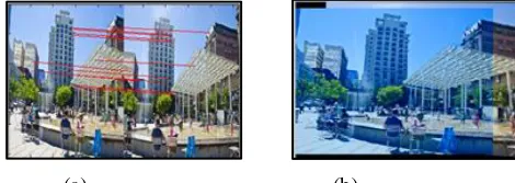
First, we detect the corners from both pairs of images to be stitched using Harris comer detection method. The detected corners have been further used for matching using similarity matrix. Fig. 3(a)shows the matching corner points of Fig. 2 and Fig. 3(b) shows the stitched image.
(a) (b)
Fig. 3: Matching corner pairs and stitched image using Harris algorithm
Table 1: Results of image stitching using Harris algorithm Sa mple
Pair
Key points (corner)
Matching points
Time in sec. Input
image1 (I1)
Input image2
(I2)
1 404 338 2 0
2 560 725 0 0
3 388 380 5 2.29
4 847 751 3 0
5 1063 1020 13 5.27
6 569 465 1 0
7 683 846 6 4.1
8 662 677 10 4.0
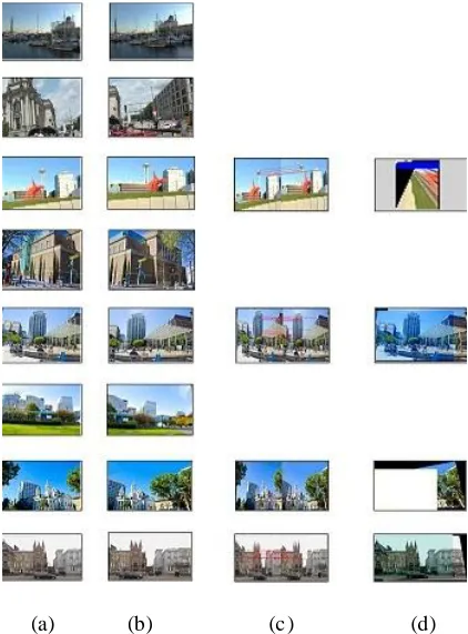
The number of corner points also called as key points detected using the Harris method for 8 images are tabulated in Table 1. These detected Harris points or Harris features have been used for matching. For instance, in Table 1 it is seen that for sample pa ir 1, 404 corner points (Input image1) and 338 corner points (Input image 2) have been detected, however only 2 points have matched i.e., only two points have similarity matrix in co mmon. Fro m this it is evident that although number of corner points detected are more in number but not so relevant to be matched for stitching. This affects the stitching process. From the results it has been observed th at the efficiency of stitching depends on the number of matching points. Therefore, we have used a threshold (if number of matching points ≥ 5 then stitch). To demonstrate the aforementioned point results are demonstrated in Fig. 4. The first column depicts the first two images for sample pair 1 fro m Table 1. The matchin g point for I1 and I2 is 2 and therefore I1 and I2 have not been stitched.
Vol. 3, Issue 4, April 2015
Fig. 4(a) and 4(b) are input images. Fig. 4(c) shows matching corners using Harris algorith m and Fig. 4(d) shows stitched image.
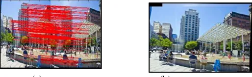
Secondly, the same stitching process was also imple mented with SIFT corner method. Fig. 5(a) shows the matching corner points of Fig. 2 and Fig. 5(b ) shows the stitched image using SIFT a lgorith m.
(a) (b)
Fig. 5: Matching corner pairs and stitched image using SIFT algorith m
Table 2: Results of image stitching using SIFT algorith m
Sa mple Pair
Key points (corner)
Matching points
Time in sec. Input
image1 (I1)
Input image2
(I2)
1 404 338 42 1.55
2 560 725 10 1.70
3 388 380 80 1.35
4 847 751 46 1.77
5 1063 1020 240 2.19
6 569 465 50 1.75
7 683 846 99 1.71
8 662 677 157 1.74
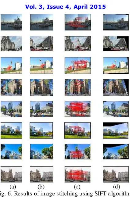
(a) (b) (c) (d) Fig. 6: Results of image stitching using SIFT a lgorithm
Fig. 6(a) and 6(b) are input images. Fig. 6(c) shows matching corners us ing SIFT algorith m and Fig. 6(d) shows stitched image.
V. CO NCLUSION
In this research work we have performed image stitching using two corner detection method name ly Harris corner detector and SIFT descriptor. We have discussed the algorithms of these two methods.
Fro m the results, we can see that the matching points of Harris algorithm is less than that of SIFT algorithm and also the image stitching done using SIFT algorithm is better than Harris algorithm. S IFT a lgorith m is more robust than Harris algorith m. A lso the correspondence point from Harris features can be obtained with high time consuming and is very difficult to get high correct point. Whereas from SIFT features we can get high correctness and robustness correspondence points.
Based on extract ing invariant scale features, we get potential feature matches for SIFT algorithm than that for Harris algorith m. SIFT can give better performance and when there are less rotations Harris corner detection algo rithms can perform better.
REFER ENC ES
[1] Minchen Zhu, Weizhi Wang, Binghan Liu, and Jingshan Huang, “A Fast Image Stitching Algorithm via Multiple-Constraint Corner Matching”, Hindawi Publishing CorporationMathematical Problem s in Engineering, vol. 2013, pp. 1-6, sep 2013.
[2] RussolAbdelfatah, Dr.Haitham Omer, “Automatic Seamless of Image Stitching”, Computer Engineering and Intelligent System s, vol. 4, no.11, pp. 7-13, 2013.
[3] Ze-lang Wang, Fang-hua Yan, Ya-yuZheng, “ An Adaptive Uniform Distribution SURF for Image Stitching”, IEEE 6th International conference on Image and Signal Processing (CISP), vol. 2, pp. 888-892, 2013.
[4] R.Karthik, A.AnnisFathima,V.Vaidehi, “Panoramic View Creation using Invariant Momentsand SURF Features”,IEEE International Conference on Recent Trends in Inform ation Technology (ICRTIT), pp. 376-382, july2013.
Vol. 3, Issue 4, April 2015
[6] Deepak Kumar Jain, GauravSexena,Vineet Kumar Singh , “Image mosaicing using corner technique”, IEEE International Conference on Communication System s and Network Technologies, pp. 79-84,may 2012.
[7] Zhen Hua, Yewei Li, Jinjiang Li, “Image Stitch Algorithm Based on SIFT and MVSC”, IEEE 7th International Conference on Fuzzy Systems and Knowledge Discovery,vol. 6, pp. 2628-2632, aug 2010.
[8] Xianyong Fang, “Feature Based Stitching of a Clear/Blurred Image Pair”,IEEE International Conference on Multimedia and Signal Processing, vol. 1, pp. 146-150, 2011.
[9] ChamindaNamalSenarathne, ShanakaRansiri, PushpikaArangala, AsankaBalasooriya, Dr. Chathura De Silva, “A Faster Image Registration and StitchingAlgorithm”, IEEE 6th
International Conference on Industrial and Information Systems, pp. 66-69, aug2011.
[10] Hyo-Kak Kim, Kwang-Wook Lee, June-Young Jung, Seung-Won Jung, and Sung-JeaKo, “ A Content -Aware Image Stitching Algorithm for Mobile Multimedia Devices”, IEEE Transactions on Consum er Electronics, vol. 57, pp. 1875-1882, no. 4,nov2011.
[11] Tao-Cheng Chang, Cheng-An Chien, Jia-Hou Chang, and Jiun-In Guo, “A Low-Complexity Image Stitching Algorithm Suitable for Embedded Systems”, IEEE International Conference on Consumer Electronics (ICCE),pp. 197-198, jan2011.
[12] Hyung Il Koo and Nam Ik Cho, “ Feature-based Image Registration Algorithm for Image Stitching Applications on Mobile Devices”, IEEE Transactions on Consumer Electronics, vol. 57, no. 3, pp. 1303-1310, aug2011.
[13] YingenXiong and Kari Pulli, “ Fast Panorama Stitching for High -Quality Panoramic Images on Mobile Phones”, IEEE Transactions on Consum er Electronics, vol. 56, no. 2, pp. 298-306, may 2010.
[14] Jubiao Li and Junping Du, “Study on Panoramic Image Stitching Algorithm”, IEEE 2nd
Pacific-Asia Conference on Circuits, Communications and System (PACCS), vol. 1, pp. 417-142, 2010
[15] TangfengXu, Delie Ming1, Liping Xiao, Chengkai Li, “ Stitching Algorithm of Sequence Image Based on Modified KLT Tracker”, IEEE 5thInternational Symposium on Computational Intelligence and Design, vol. 2, pp. 46-49, oct2012
[16] Xian-Guo Li, Chang-Yun Miao and Yan Zhang, “An Algorithm for Selecting and Stitching the Conveyer Belt Joint Images Based on X-ray”, IEEE International Conference on Intelligent Compu tation Technology and Automation,vol. 1, pp. 474-477, may 2010.
[17] Oh-Seol Kwon and Yeong-Ho Ha, “Panoramic Video using Scale-Invariant Feature Transform with Embedded Color-Invariant Values”, IEEE Transactions on Consumer Electronics, vol. 56, pp. 792-798, no. 2, may 2010
[18] Y. Zhang, G. Gao, and K. Jia, “A fast algorithm for cylindrical panoramic image based on feature points matching,” Journal ofImage and Graphics, vol. 14, no. 6, pp. 1188–1193, 2009.
[19] W. Zhao, S. Gong, C. Liu, and X. Shen, “A self-adaptive Harris corner detection algorithm,” Computer Engineering, vol. 34, no. 10, pp. 212– 214, 2008.