Volume 41– No.2, March 2012
ABSTRACT
This paper describes the use of wireless sensor network for streetlight monitoring and control. As we look at existing systems the power consumption and maintenance cost of streetlight control department is high. This system would provide an optimal costing for streetlight maintenance and control. System employed use of network processing device (nodes) for sensing of light and then gathered information is used for controlling streetlight ON/OFF or streetlight intensity. Life of Street Lamps depends on the duration for which they get used. In this research, I will try to reduce the required duration for which lamp should be ON, focuses on increasing frequency band for network nodes to get maximum possible data rate and also discuss the parameters required to automatic detection and removal of nodes in the network. This paper also discusses the cost comparison between current system, sensor control system and this system with profile implementation.
Keywords
Jennic wireless microcontroller JN – 5139, Network processing device, streetlight, Supervisory control.
1.
INTRODUCTION
In today‟s competitive world where demand for internets, intranets and telecommunications are increasing, wired networks are beginning to lose its significance. The scenario is best described with use of street lights having wired networks. In wired networks, the installation cost, maintenance of street lights, power consumption, monitoring and management of street lights are the various problems that are rising up. Such complexities can be easily removed by using the concept of Wireless Sensor Networks.
A wireless sensor network (WSN) is a wireless network consisting of spatially distributed autonomous devices using sensors which works corporately to monitor physical or environmental conditions, such as temperature, sound, light, vibration, pressure, at different locations.
Unique characteristics of a WSN include: Ability to cope with node failures Mobility of nodes
Dynamic network topology
Tolerance to communication failures Heterogeneity of nodes.
This system comprises of control station (PC), a GUI to display and update status of street light, and network processing devices (NPD) .The nodes and NPD are Jennic 513x wireless microcontroller with different programming. The master, nodes and NPD have light sensors embedded in them. A threshold value (in LUX) is set up at the master. The nodes will sense the light intensity and send the value to the master. The master compares these values with the threshold value and appropriately decides whether to switch ON/OFF the nodes. The GUI gives us a representation of the streetlights i.e. their status (ON/OFF) [3][6][7][8]. This
consumption, ease of monitoring and controlling and less installation cost are the various advantages achieved [1][2][3]. My main research work includes making of this system to automatically detect new nodes in the system so as to possible to make network adaptive to forthcoming changes.
2.
LITERATURE
SURVEY
Wireless Sensor Network (WSN) is a wireless network consisting of spatially distributed autonomous devices using sensors to cooperatively monitor physical or environmental conditions, such as temperature, sound, vibration, pressure, motion or pollutants, at different locations In addition to one or more sensors, each node in a sensor network which typically equipped with a radio transceiver or other wireless communications device, a small microcontroller, and an energy source, usually a battery. The envisaged size of a single sensor node can vary from shoebox-sized nodes down to devices the size of grain of dust [17][18][19][20], A sensor network normally constitutes a wireless ad-hoc network, meaning that each sensor supports a multi-hop routing algorithm (several nodes may forward data packets to the base station).
2.1 Details of Same Kind of Work
2.1.1 Dynamic Public Lighting (DYNO)
In Netherlands the system installed and operated is a dynamically lighted roadway that can be adjusted to any of three lighting levels, depending on the amount of traffic, time of day, and weather conditions [1][11] The low level is 0.2 cd/m2, the normal level is 1 cd/m2 and the high level is 2.0cd/m2. The wireless communication uses frequency band of 900 MHz which ultimately results in lower data communication rate. In an evaluation of DYNO, it was concluded that, under low traffic volume and favorable weather conditions, the low level (0.2 cd/m2) can be applied.
2.1.2
Tyco Electronic systems
An “Intelligent Street Lighting and Street Light Monitoring” system has been developed which maximizes energy saving and minimizes unwanted light (as light pollution), but takes account of the environment and safety standards needed in all traffic conditions [2][4][7]. The energy saving is achieved by driving each light source to the minimum illumination, needed for specific time and weather conditions. Planned settings can be overruled by environmental conditions such as heavy rain, visibility, frost, traffic density and much more. The requirement for the light level needed during each condition can be predefined.
2.1.3 Video Sensor Networks In Traffic
Surveillance
In this system the camera is used for calculation of road traffic density, the speed of cars, the details of the license plates of over-speed cars and the vehicle flow dimensions in a certain direction. This information is used to control the illumination of street light depending on road traffic conditions and weather conditions at specific geographical location. In video sensor networks the transmitted information of the video has
Deepak Kapgate
G.H. Raisoni College of engineering,
Nagpur University
,
Volume 41– No.2, March 2012 been compressed. As a matter of fact, in the existent
well-developed traffic surveillance systems, the process of image gathering, image processing, data fusion and information transmitting have been implemented using cameras.
2.1.4 Supervisory Control and Monitoring System
The main functions in ÖSÖ are: Map overview based on information from the Traffic Authorities own GIS-system.
Status monitoring.
Fault monitoring and fault distribution by SMS to service personnel.
Light control – On/Off on the basis of light intensity or manually from a Web site.
Data collection and report (energy consumption, burning hours, etc).
For controlling and monitoring of street lights some existing technology such as PLC may be used but as PLC technology has some problem such as cost, noice, communication failure. So, I use ZIGBEE wireless sensor network for monitoring and controlling of streetlight. In research work done up till now, controlling of streetlight using ZIGBEE [5][6][9] the problems which persist are detection of new nodes in network, refreshing network parameters and the ISM frequency band used is some tens of MHz which ultimately results in reduction of data rate. In this paper my main research work includes making it possible to detect new nodes in network automatically, increase the data rate capacity of network nodes (NPD) using Jennic JN-5139 microcontroller which has frequency band up to 2.4 GHz. I have used this system for cost reduction in M.S.E.B. Maharashtra, India. It results in saving of 5.85 core per month + additional manual and maintenance cost spent for streetlight monitoring and controlling.
Here, the remote terminal unit will serve as relay station between the control center and the sensor nodes. The control center will monitor and control all streetlight real times [10]. The system application in streetlight control for each lamp will reduce in streetlight electricity and maintenance cost, and increase availability of street light [9][12][13]. As well as, Streetlight Monitoring and Control System will provide remote streetlight control, will optimize streetlight uptime and will extend lamp life. I will explore this system in the context of a concrete application that of monitoring street Light control in a dense urban environment.
3. SOFTWARE REQUIREMENT
SPECIFICATION
3.1
Hardware Requirements
JN513x evaluation kits [17][18]. A machine (PC) with 256 MB memory, HDD, serial ports USB 2.0, etc [19][20].
3.2
Software Requirements
IDE to write and program the Trans-receiver assembly. PC based data collection, analysis module.
Various hardware interface modules their design and development.
MS Visual Studio 2005/2008 for interface development. Suitable high level programming languages.
3.3
System Statement
To create near to real time environment for working of WSN based Street Light Control System and test performance and working of that application.
To sense real time light intensity by the Ambient light sensor and depending upon the sensed light intensity take appropriate control action on the Street Light(End Device) To create library of several modules to simulate the
network condition parameters.
To provide graphical user interface to control and monitor the status of Street Light.
To give graphical simulation of light intensity to the user.
3.4
Modules
The master, NPD and ED side programming for implementation of the Street Light Application.
The master, NPD and ED programming for creating the database of entire network at master side.
Accepting the Node‟s status command from the user and accordingly set status of the Street Light.
Accessing the current status of the Street Light (Get Status) from the End Device.
Periodically sending of the Sensed Light Intensity Values from the End Devices to the Master Node.
4. ASSUMPTIONS AND PREREQUISITES
The first Node Processing Device (NPD) is always in therange of the Master.
The remaining Node Processing Device (NPD) are also always in the range of its preceding NPD.
The user is at Control Station i.e. the Master Node, which is the governing device of wireless sensor network. The user must be aware of working wireless sensor
network based application [4]. User must provide proper network setup parameters for WSN based application. Environmental Conditions such as rain, snow, storms etc.
can affect the System performance.
The Master node must function properly during entire working, i.e. it should not fail in the due procedure.
Volume 41– No.2, March 2012
Fig. 1: Administrator Use Case Diagram
User who wants to access system needs to provide the network setup parameters to system. System will accept the required parameters. Initialization of network is done by creation of tree topology at master side and it is made available for processing. Admin who wants to set status ON/OFF a particular node he needs to execute command, and need to provide required parameters for command execution. This will be processed by system. Admin who wants to get status ON/OFF a particular node he needs to get the status of a particular node and depending on node status he has to give proper command. Node senses the light intensity and according updates its status (ON/OFF). Node Sense the light intensity and compares the light intensity with the Threshold set. Comparing the light intensity with the Threshold, the node ON‟s its street Light if light intensity sensed is less than
[image:3.595.319.539.81.401.2]Threshold value and OFF‟s its street Light if light intensity sensed is greater than Threshold.
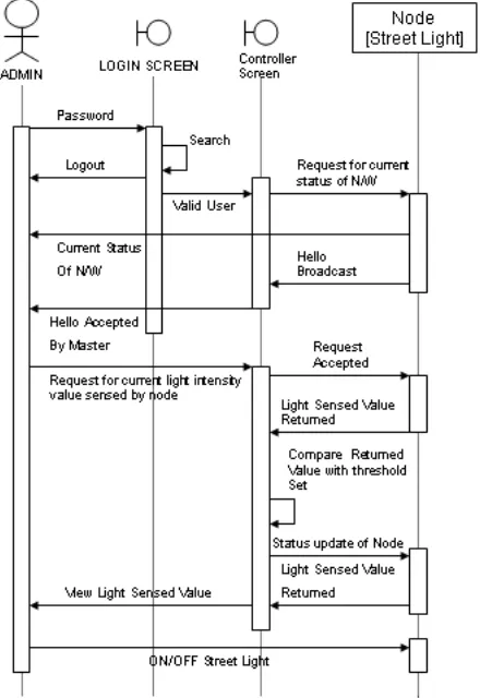
Fig. 2: Sequence Diagram for Get and Set Status
As shown in (figure 2) administrator has authority of requesting status of node in the network. Administrator sends a request for current status of network. The nodes responded to request with “HELLO” broadcast which is accepted by master. Then administrator sends the request for current light intensity value sensed by node. The light sensed value is compared with threshold value and the status update of node either ON or OFF send. The (figure 3) shows sequence diagram for detecting whether new node added or not. If yes the system refreshes network.
[image:3.595.152.437.563.737.2]Volume 41– No.2, March 2012
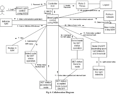
Fig 4: Collaboration Diagram
As shown in (figure 4) the collaboration diagram shows the messages and operating that classes within a system must support in order to perform some desired behavior or functionality and the association that must exist between classes to enable the message to flow among them. As shown in the diagram the controller of system resides in the center.
The initialization of system involves setting communication parameters and detection of new nodes. The operations such as GET status and SET status of nodes performed independently with required node. The automatic ON/OFF of node is depending upon the light intensity sensed by node and threshold value settled initially.
7.
IMPLEMENTATION
DETAILS
7.1 Programming A Hardware
7.1.1 Jennic Wireless microcontroller JN-5139
evaluation system:
[image:4.595.316.541.442.690.2]The hardware that I have used for my system is „Jennic Wireless microcontroller JN-5139 evaluation system‟ as shown in (figure 5)
Fig. 5: Jennic Wireless Microcontroller JN-5139
Volume 41– No.2, March 2012
RISC CPU, on-chip memory and an extensive range of peripherals.
7.1.2 PROGRAMMING TOOL AND IDE:
The programming and main coding of my system is done using IDE provided by Jennic Wireless microcontroller JN-5139 evaluation system, “Jennic: Code:blocks IDE” (version: svn build rev 3466). The programming is done in „C‟ programming language with standard APIs provided by Jennic Wireless microcontroller JN-5139 evaluation system. The “Jennic: Code:Blocks IDE” provides a developing environment for programming Jennic Wireless microcontroller JN-5139 evaluation system.
7.2 Modules of Application:
7.2.1 Setting of network parameter
This module accepts network setup and connection establishment parameters such as baud rate, parity, stop bits, no. of data bits and COM port no. for serial communication. On successful establishment of connection it gives timing details and address of device.
7.2.2 Receiving node list from the network
After providing the Network parameters to the System the system sets up the Network. If new nodes are added to the network then, the system takes a small period of time to detect new nodes and add them to the network. The nodes broadcast its “HELLO” message which is subsequently received by the Master Node. The node detection is verified by the “List Receive Message”.
7.2.3 Viewing the Node List of the nodes present
in the Network
After the complete setup of the network the Nodes present in the network are presented to the administrator. The Nodes are represented by their node number, their current status and also the number of nodes present in the Network.
7.2.4 Set status of a particular node
Administrator can Select a particular node and update its status i.e. ON/OFF. The administrator provides the necessary command to set the Node ON and OFF. A value 1 is entered as a command by the Administrator to turn the Street node ON and value 0 is entered as a command to turn the Street node OFF.
7.2.5
Set status of a particular node is switched
ON/OFF
After the Set status value provided by the Administrator to the selected node, its status is updates as ON/OFF. A Bulb showing a YELLOW color glow is used to indicate that the Node is turned ON.A Bulb showing a WHITE color glow is used to indicate that the Node is turned OFF.
7.2.6
Get status of a particular node
The Administrator has the control over the function to view the current status of any particular node in the Network. The Command that does this function is known as GET STATUS. This Command returns the current status of the node An YELLOW colored indicates an ON status. A WHITE colored indicates an OFF status.
7.2.7
Refresh Network for Detecting and adding
new nodes to the Network
The refresh network command provides the Administrator the functionality to check for new nodes wanting to join the Network. This command does the same functionality as the Network setup operation. The Nodes are represented by their node number, their current status and also the number of nodes present in the Network. Already existing Nodes in the network also are detected once again in the Network Refresh operation
8. RESULTS
8.1 Current Scenario Of Street Light
System (Data Collected From M.S.E.B. –
Pune, (M.S.), India)
Height of Street Light : 7m, 8m, 9m, 10m.
Power : 70 Watts for 7m & 8m poles 150 Watts for 9m pole. 250 Watts for 10m pole Distance between successive street lights:
19-20m (between 7-7m and 8-8m poles) 24-25m (between 9-9m and 10-10m poles) Distance between poles depends on width of the roads.
Phase : Single phase (230V) and Three Phase (440) Used together
Lamps : Sodium Vapor Lamps. Network : Arranged in parallel network. Linear control : No linear control available on lamps. Timer : Use of Intelligent Timer
Lamps/Timer : 3Kw-5Kw load per timer (20 -30 lamps)
Number of Timers : 2500
Number of Lamps : 62500(25 Lamps per Timer) Number of Energy units Utilized:
4166000 per month approximately Monthly Bill : 1.25 crore (Rs. 3 per unit)
8.2 Energy Utilization
8.2.1 Current System
Works on profile basis i.e. all street lights are ON from 6:30 pm to 6:30 am, in other words street lights are functioning completely for 12 hrs a day. Assuming 20 nodes to be working power consumed by them will be given as,
Bulb used =150 W=0.150 Kw, Number of nodes = 20 nodes, Number of working hrs per day = 12 hrs Power Consumed per day = 20 * 12 * 0.150
= 36 Kwhr i.e. 36 * 30 = 1080 Kwhr/month Monthly Bill for 20 nodes (Rs 3/kwhr ) = 1080 * 3 = 3240 Rs per month
8.2.2 This Street Light Control System
CASE 1: All Lamps ignited.
This system works on the Sun light intensity, if the light intensity goes below a certain predefined value, then the lamp turns ON and turns OFF if the light intensity sensed is more. Therefore the power consumed by the street light is less than the current system being implemented. Assuming 20 nodes to be working power consumed by them will be given as,
Considering a summer season day, where light intensity gets low by 7:30 pm and light intensity becomes more by 6:00 am
Volume 41– No.2, March 2012
Number of working hrs per day = 10.30 hrs
Power Consumed per day = 20 * 10.5 * 0.150 = 31.5 Kwhr
i.e. 31.5 * 30 = 945 Kwhr/month Monthly Bill for 20 nodes (Rs 3/kwhr ) = 945 * 3
= 2835 Rs per month
CASE 2: System with Profile implementation.
Considering the above mentioned case, where light intensity gets low by 7:30 pm and light intensity becomes more by 6:00 am
Bulb used =150 W=0.150 Kw, Number of nodes = 20 nodes,
Consider the following profile =
7: 30 pm to 11: 30 pm all nodes ON (Heavy traffic) 11: 30 pm to 4: 30 pm alternate nodes ON (Low traffic) 4: 30 pm to 6: 00 pm all nodes ON (Heavy Traffic)
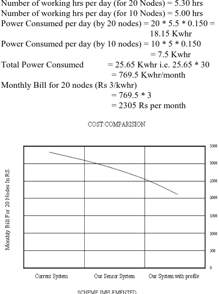
Number of working hrs per day (for 20 Nodes) = 5.30 hrs Number of working hrs per day (for 10 Nodes) = 5.00 hrs Power Consumed per day (by 20 nodes) = 20 * 5.5 * 0.150 =
18.15 Kwhr Power Consumed per day (by 10 nodes) = 10 * 5 * 0.150
= 7.5 Kwhr Total Power Consumed = 25.65 Kwhr i.e. 25.65 * 30
= 769.5 Kwhr/month Monthly Bill for 20 nodes (Rs 3/kwhr)
= 769.5 * 3
[image:6.595.53.278.284.587.2]= 2305 Rs per month
Fig. 6: Cost Comparison of different schemes
8.
CONCLUSION
This research paper work is an attempt to develop a Street Light Control and Maintenance using WSN based application. I have made use of the Sensor for the Street Light application which aims to reduce the power consumption. The control center will monitor and control all streetlights at real time. The network has capability of automatic detection and removal of nodes. I have done real time modeling for network layer protocols. There is great scope for future work in this area. The future work may include sensor position tracking, more increased data transfer rate and reduction in initial investment cost. I hope that this paper work will be of great benefit to the WSN based application developers.
9. ACKNOWLEDGMENTS
The author is thankful to Dr. Preeti Bajaj, Director G. H. Raisoni College of Engineering, Nagpur for moral encouragement and providing necessary facilities.
10. REFERENCES
[1] Reza Mohamaddoust , Abolfazl Toroghi Haghighat, Mohamad Javad Motahari Sharif and Niccolo Capanni, “A Novel Design of an Automatic Lighting Control System for a Wireless Sensor Network with Increased Sensor Lifetime and Reduced Sensor Numbers”, Sensors (2011) ,Volume No.- 11(9), pp. 8933-8952.
[2] De Dominicis, C.M.; Flammini, A.; Sisinni, E.; Fasanotti, L.; Floreani, F.; “On the development of a wireless self localizing streetlight monitoring system “, Sensors Applications Symposium IEEE, pp. 233 - 238 ,2011.
[3] Gustavo W. Denardin, Carlos H. Barriquello, Alexandre Campos, Rafael A. Pinto, “Control Network for Modern Street Lighting Systems”, IEEE symposium on Industrial Electronics (ISIE), (2011), pp. 1282 – 1289.
[4] Jing Chunguo, Wang Yan Sun, Wenyi Song, “Design of Street Light Pole Controller Based on WSN”, The Tenth International Conference on Electronic Measurement & Instruments, ICEMI (2011), pp. 147 – 150.
[5] Chun-ling Fan and Yuan Guo, “The Application of a ZigBee Based Wireless Sensor Network in the LED Street Lamp Control System”, International Conference on image Analysis and Signal Processing (IASP), 2011, pp. 501 – 504.
[6] Shentu, Xudan; Li, Wenjun; Sun, Lingling; Gong, Siliang, “A new streetlight monitoring system based on wireless sensor networks”, International Conference on Information Science and Engineering, pp. 6394 – 6397, 2010.
[7] Wu Yue; Shi Changhong; Zhang Xianghong; Yang Wei; “Design of new intelligent street light control system “,, 8th IEEE international Conferences on Control and Automation (ICCA), ( 2010) , Page(s): 1423 – 1427.
[8] Hengyu Wu; Minli Tang; Guo Huang, “Design of multi-functional street light control system based on AT89S52 single-chip microcomputer”, , IEEE 2nd International Conferences on Industrial Mechatronics and Automation (ICIMA), (2010 ), Page(s): 134 – 137.
[9] J. L. Huang, Z. F. Wang, L. G. Li, and L. H. Wang,” Based on ZigBee smart wireless lighting wall controller design,”Chinese Journal of Scientific Instrument, vol. 30, no. 6, June 2009.
[10] I.-K. Rhee, J. Lee, J. Kim, E. Serpedin, and Y. C. Wu, “Clock synchronization in wireless sensor networks: An overview,” Sensors (2009), Volume no. 9, pp. 56–85.
[11] Andreas Willig,”Recent and Emerging Topics in Wireless Industrial Communications: A Selection”, IEEE Transactions on Industrial informatics, (2008) Volume: 4 (2),pp. 102 – 124.
Volume 41– No.2, March 2012
Industrial Electronics and Applications (2007), pp. 57 – 62.
[13] Lee, J.D.; Nam, K.Y.; Jeong, S.H.; Choi, S.B.; Ryoo, H.S.; Kim, D.K.; “Development of Zigbee based Street Light Control System”, IEEE Conferences on Power Systems, (2006) , pp. 2236 – 2240.
[14] S. Chen, G. Fan, and J. Cui, “Avoid ‟void‟ in geographic routing for data aggregation in sensor networks,” Int. J. Ad Hoc Ubiquitous Comput., vol. 1, no. 4, pp. 169–178, 2006.
[15] G. Zhou, T. He, S. Krishnamurthy, and J. A. Stankovic, “Impact of radio irregularity on wireless sensor networks,” in in MobiSYS 04: Proceedings of the 2nd international conference on Mobile systems, applications, and services. ACM Press, 2004, pp. 125– 138.
[16] A.Boulis and M.B.Srivastava , “A Framework for Efficient and Programmable Sensor Networks”, IEEE OPENARCH 2002, pp.117- 128.
[17] I.F.Akyildiz, W.Su.Y.San and E.Cayirci, "A Survey on Sensor Networks," IEEE Communications Magazine, pp. 102-114, Aug. 2002.
[18] IEEE Std. 802.15.1, “Wireless Medium Access Control (MAC) and Physical (PHY) Specification for Wireless Personal Area Networks (WPANs),” 2002.
[19] J. A. Gutierrez, M. Naeve, E. Callaway, M. Bourgeois, C. Mitter, and B. Heile, "IEEE 802.15.4: A developing standard for low-power low-cost wireless personal area networks," IEEE Network, vol. 15, pp.12--19, Sept.-Oct. 2001.