R E S E A R C H
Open Access
QoS-aware resource management for
LTE-Advanced relay-enhanced network
Jacek Góra
1,2Abstract
Relaying is one of the major innovative concepts proposed in the recent years for cellular radio communication systems. It is a perfect solution for dealing with the issue of high variability of performance in cellular networks. By coordinated deployment at cell-edge or in shadowed areas, relay nodes can extend network coverage and increase the low end-user performance. Considering the advantages, relaying is recently being included in the standards of the fourth generation systems such as the LTE-Advanced and the WiMAX. However, one major problem of relaying is still to be resolved. Specifically, there are no concrete concepts for quality-of-service provisioning for relayed transmissions. This paper investigates the case of packet delivery times over multi-hop links in relay-enhanced networks. The discussion is specifically based on relaying implementation in the LTE-Advanced system. The quality-of-service satisfaction and its fairness for the base station and relay-node-connected users are analyzed in the framework of the utility theory. For the purpose of this analysis, utility functions are proposed for real-time traffic with minimum data rate and/or maximum packet delivery time requirements. Furthermore, several optimization concepts are proposed for managing multi-hop transmissions in a quality-of-service aware manner. The included analysis based on the LTE-Advanced system level simulations shows that the proposed optimizations have the potential to improve the overall quality-of-service satisfaction in a relay-enhanced system.
Keywords:LTE-Advanced; Relaying; Radio resource management; Utility theory; Quality-of-service; Delay
1 Introduction
In the year 2008, the International Telecommunication Union, Radiocommunication Sector (ITU-R) issued the M.2134 report [1] specifying requirements for the next generation of radio communication systems, the so-called International Mobile Telecommunication-Advanced (IMT-A). Specification of those requirements started a still ongoing process of developing new solutions extending capabilities of the existing radio communication systems. The research and development process leads to the defin-ition of two major fourth generation (4G) systems, i.e., the Long Term Evolution-Advanced (LTE-A) [2,3] and the Worldwide Interoperability for Microwave Access (WiMAX) Release 2 [4,5].
Both the LTE-A and the WiMAX include a similar set of techniques to meet the IMT-A requirements [5-7].
The most significant building blocks considered are the following:
Advanced multi-antenna techniques (multiple-input
multiple-output, MIMO) [8],
Bandwidth extension in the form of, e.g., carrier aggregation (CA) [9],
Heterogeneous networks (HetNets) [10], and
Improved interference mitigation techniques
including interference avoidance [11] and coordinated multi-point (CoMP) transmission schemes [12].
One of the novel techniques proposed for the two 4G systems is relaying (in the above listing classified as part of the HetNet concept). The baseline of this technology is the introduction of a new type of access points, relay nodes (RNs), capable of dynamic setting-up its own backhaul (BH) link connection over a common radio interface, i.e., the same that is used for serving users (e.g., Correspondence:[email protected]
1Technology and Innovation Department, Nokia Networks, Pl. Gen. J. Bema 2, 50-265 Wroclaw, Poland
2Faculty of Electronics and Communication, Poznan University of Technology, Ul. Piotrowo 3A, 60-965 Poznań, Poland
the LTE-A). Donor of the BH link connectivity is a stand-alone access point (donor node (DN)), or in other more advanced configurations, already operating, RN (i.e., the donor RN (DRN)). The main benefits of relaying envi-sioned for cellular systems are the following:
Accuracy in coverage provisioning - RNs, as low
power nodes, can be deployed exactly at the location where network coverage is required (including indoor or strongly shadowed areas) [13,14]. RNs specifically can be also deployed in locations where wireline BH provision is not possible (e.g., in public transport vehicles [15]).
Low cost - RNs are commonly envisioned as low
power and simple devices, in addition to not requiring fixed wireline BH connection, this enables for network operator savings in both capacity and operational expenditures [16].
Flexibility of use - possibility to provide rapid and/or short-term deployments of network infrastructure (e.g., for mass events or for disaster/network malfunction recovery) without earlier planning or investments [17].
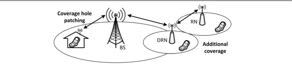
The basic application scenario for relaying (as specified by the 3rd Generation Partnership Project (3GPP) forum [18]) is coverage extension. The coverage extension sce-nario assumes that the main purpose of RNs in a cellular network is to provide additional system coverage and to enhance connection quality for the macro cell-edge users or the users located in macro coverage holes. Illus-tration of the relaying coverage extension scenario is presented in Figure 1.
The simplest application of relaying for coverage ex-tension is deployment of RNs at the edge of a macro-cell coverage [19,20]. In such a case, the RNs initiate their own cells providing improved connection conditions for the nearby users (access, AC, link connectivity) and es-tablish BH link connection to the overlaying macro base station (BS). This is the so-called two-hop relaying top-ology [21] (see Figure 2).
In a more advanced implementation, RNs may also estab-lish BH link connection to other RNs. The topology is then called the multi-hop relaying [22] (see Figure 2). In general case, the multi-hop relaying topology may have the struc-ture of a tree or a mesh. From an implementation perspec-tive, however, the tree topology is generally preferred [23].
On the current development stage, the relaying tech-nique is considered to provide coverage extension on the basic accessibility level. The LTE-A system specifica-tion does not provide yet any dedicated mechanisms for explicit capacity enhancement or quality-of-service (QoS) management. This is often pointed out as the main short-coming of the existing relaying solutions [21,24].
The most relevant problem of the relaying technique regarding QoS provisioning is the introduction of add-itional delays to the packet delivery time in the radio interface. The additional delays are related to the multi-hop transmission and the RN signal processing times at each hop. Furthermore, the basic LTE-A relaying imple-mentation assumes time domain multiplexing (TDM) of the RN BH and AC links (i.e., the in-band operation scheme [3,22,25]), which even further increases the end-to-end transmission time.
This paper investigates the QoS provisioning problem for the RN-connected users. The main focus is put on the packet delivery time issue, but the requirement of mini-mum data rate is also considered. Firstly, in Section 2, the QoS-provisioning problem for relayed transmissions is formulated. In Section 3, the weight of the problem is ana-lyzed in the context of the LTE-A standard specification of relaying. This includes analysis of the available relay node configurations with respect to the impact they have on the end-user perceived packet delivery times. Next, in Section 4, resource management schemes based on the utility theory are proposed. The purpose of the proposed schemes is to optimize the resource allocation in a relay-enhanced network (REN) so to improve the gen-eral QoS satisfaction for all users. Efficiency of the pro-posed solutions is verified via LTE-A system-level simulations described in Section 5 of this paper. Finally, the work is concluded in Section 6.
2 Problem formulation
QoS provisioning for real-time traffic involves two ele-ments [26]:
Satisfaction of the minimum required data rate (i.e., the guaranteed bit-rate (GBR)), and
Satisfaction of the maximum packet delivery time (i.e., the packet delay budget (PDB)).
Listing of the 3GPP standardized QoS classes with in-dication of the corresponding GBR and PDB require-ments is depicted in Table 1.
To provide QoS satisfaction for a real-time traffic, both the GBR and PDB requirements need to be satis-fied. If the GBR requirement is not met, it is not pos-sible to guarantee the packet delivery times for all data packets. In such a case, the scheduling process in un-stable [27], i.e., new data packets are created by the source node(s) faster than they are delivered to the tar-get node(s).
On the other hand, even if the GBR requirement is satis-fied, the PDB requirement cannot be assumed to be auto-matically satisfied [27]. It can be generally considered that
the packet scheduling algorithm, if non-optimally imple-mented, may make some data packets wait in queue lon-ger than allowed by the PDB requirement while instead scheduling for transmission packets with longer available time to drop.
In the case of relayed connections, the same rules apply. The task of the QoS satisfaction is, however, additionally complicated by the multi-hop nature of the transmission process.
First of all, in case of an H-hop connection, each data packed is send overHcomponent radio links. Thus, it isH times queued in buffers, processed for link adaptation, and transmitted over the radio interface. At each transmission, hop errors might be introduced, which require additional retransmissions and may cause further delays in the packet delivery. Considering anH-hop connection, the end-to-end delivery time (te2e) for a data packet can be generally esti-mated as the sum of the number of times required to per-form the three aforementioned operations at each of theH transmission hops, i.e., as follows:
te2e¼ X
h¼1
H
tp;hþtq;hþtt;h
ð1Þ
wheretp,his the packet processing time,tq,his the packet queuing time, and tt,h is the packet transmission time over a single hop (including retransmissions, if any). Sub-scripthindicates the number of a hop in theH-hop con-nection chain.
Based on Equation (1), the first estimation of the packet delivery time over anH-hop connection is that it is on averageHtimes higher than the time expected for a single-hop connection. However, this simple estima-tion is not true as transmissions on the component links of a relayed connection are not independent.
The end-to-end packet transmission times over multi-hop links are also impacted by the RN buffer capacity and its fill level at each of the relaying hops. This might not be critical nor even noticeable if the system load is low (i.e., RN buffers are never fully loaded). However, as indicated in the work of Vitiello et al. [28], if the system
Figure 2Two-hop and multi-hop relaying topologies.
Table 1 Standardized QoS classes [26]
QoS class
Priority Bit rate requirement
PDBa
(ms) Packet error rate
Service example
1 2 GBR 100 10−2 Live voice streaming
2 4 150 10−3 Live video streaming
3 3 50 10−3 Real-time gaming
4 5 300 10−6 Buffered video
streaming
5 1 Non-GBR 100 10−6 IMS signalling
6 6 300 10−6 Web traffic for
privileged users
7 7 100 10−3 Interactive gaming
8 8 300 10−6 Web traffic for
standard users
9 9 Elastic traffic
a
load is high, RN buffers might get congested and be-come bottlenecks for multi-hop transmissions.
As shown in the author’s earlier work [29], the im-pact of limited capacity of the RN buffers is especially noticeable if capacities of the RN BH and AC links are improperly balanced, e.g., as a result of sub-optimal re-source allocation. If capacity of the RN BH link is lower than capacity of the RN AC link, data packets transmitted downlink to the user will get congested at the RN’s donor node buffer. If the capacity of the RN BH link is higher than the capacity of the RN AC link, data packets transmitted downlink to the user will get congested at the RN buffer. For uplink transmissions, inverse process takes place.
Overall, it can be stated that the QoS-aware resource management for a multi-hop connection has to con-sider parameters of all its component links and in-volved RNs to secure the end-to-end QoS satisfaction. Such operation is beyond the existing LTE-A relaying specification that considers an RN as an access point with an autonomous resource management and packet scheduling functionalities (i.e., the layer-3 RN model [3,22]). This paper describes a multi-node resource man-agement and scheduling scheme that can potentially solve this problem.
Before designing a resource management and sched-uling procedure for relaying, it is curtail to get a full understanding of the RN configuration schemes sup-ported by the LTE-A system. Therefore, in the next section of this paper, it is analyzed up to what extent the LTE-A relaying configurations are able to satisfy the QoS requirements of real-time services and what impact they have on the packet delay budget.
3 LTE-A relaying implementation
The basic relaying mode of operation considered in the LTE-A system standard and in most of the other imple-mentations is the decode-and-forward (DF) approach [21]. In case of the DF relaying, a delay of at least one radio sub-frame is introduced at each RN in the multi-hop connection. The delay relates to the DF signal pro-cessing time, i.e., decoding of the signals received on the feeder link (i.e., RN BH in case of downlink transmis-sions) and encoding them again for transmission on the outgoing sink link (i.e., RN AC in case of downlink transmissions).
As the result of the DF processing, the transmissions tak-ing place on the RN BH and AC links are not correlated. Therefore, the transmissions outgoing from a RN generate interference at the RN feeder link receiver [30]. To avoid the RN self-interference, two options are available [3]:
Separation of the RN BH and AC transmissions by
either allocation of orthogonal radio resources (e.g.,
frequency carriers as in the out-band relaying [3,22]) or by separation of the RN AC and BH antennas (e.g., by usage of directional antennas or antenna displacement).
Time domain multiplexing of the RN BH and AC
transmissions so that they are not active at the same time (i.e., the in-band relaying [3,22]).
Relaying implementations with the two self-interference avoidance options are analyzed next. The purpose of the analysis is to define the lower bounds of the end-to-end transmission delays (tLB
e2e) for multi-hop connections in-volving RNs of either of the two configurations described above. The delay lower bounds are defined as the trans-mission times in an unloaded system, i.e., without the queuing times considered, i.e.,
tLB
where inf(.) is the infinum function.
3.1 Full-duplex relaying
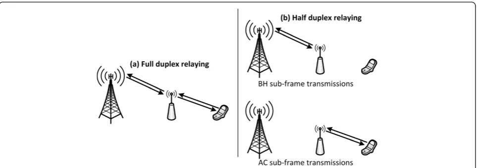
If sufficient separation is provided to the RN BH and AC links, the two links can be operated simultaneously (see Figure 3a), i.e., the RN can receive transmissions on the feeder link at the same time as it transmits on the sink link (full-duplex (FD) operation). In such case, the RN can forward data to the target node as soon as it re-ceives and processes the transmission from the source node.
Based on the above characteristic, Equation (2) can be reformulated for the full-duplex relaying as follows:
tLB−FD
whereyhis the data rate achieved by the user’s transmis-sion on the component link h, and ⌈.⌉ is the ceiling rounding function. Equation (4) can be next simplified as the following:
the effective end-to-end data rate of the multi-hop con-nection (ye2e), thus
tLB−FD e2e ¼
⌈
S ye2e
⌉
þXH
h¼1
tp;h ð6Þ
which can be finally reformulated as
tLB−FD e2e ¼
⌈
S ye2e
⌉
þtBS
p þðH−1ÞtRSp ð7Þ
where tpRN and tpBS are the packet processing times at RNs and BSs, respectively.
Compared to a single-hop transmission of the same end-to-end data rate (ye2e), theH-hop FD relaying trans-mission time is longer by at least the (H −1) tpRN elem-ent. Considering that the RN processing delay tpRN should be in the range of 1 up to few milliseconds, the additional delay of a full-duplex multi-hop connection should not be critical considering the PDB requirements of most service types (see Table 1). However, in loaded systems, the queuing delay will be non-zero at some or all transmission hops. This delay, if not properly handled, can make the significant difference in the end-to-end packet delivery time. Therefore, a QoS-aware packet scheduling is so crucial for relaying. Proposal of such a scheduling al-gorithm is given in Section 4 of this paper.
3.2 Half-duplex relaying
In case sufficient separation of the RN BH and AC is not provided, the two links should be time domain multi-plexed (TDM, see Figure 3b). The TDM-based resource partitioning implies that a RN operates in a half-duplex (HD) mode, i.e., the RN does not transmit and receive at the same time per transmission direction (downlink and uplink).
The TDM of RN BH and AC links provides protec-tion from the RN self-interference without the need of either advanced hardware solutions or additional fre-quency resources as in case of the FD relaying. Consid-ering the advantages, the TDM-based RN mode of operation is the main one currently considered in the LTE-A standardization [3,18].
The LTE-A system standard implements the RN TDM by reusing the LTE Release-8 multimedia broadcast over single frequency network (MBSFN) mechanism [31]. It defines that certain time sub-frames (duration of one LTE-A sub-frame is 1 ms) may be assigned for RN BH op-eration while the remaining sub-frames are used for the RN AC communication with users. Due to backward com-patibility reasons, selection of the BH-enabled sub-frames is not fully flexible. The restrictions in the sub-frame con-figuration and the TDM itself generate additional delays on top of the delays already identified for the FD relaying (see Section 3.1).
The allowed BH MBSFN sub-frame patterns can be characterized with the following statistics that directly impact the performance of the HD relaying:
Number of the BH sub-frames (KBh). This statistic
determines the capacity of the RN BH link. It also controls the RN BH-AC capacity balancing for avoiding transmission bottlenecks [29]. The RN BH operation time share (σ) related to the MBSFN configuration is as follows:
σ¼KBh
K ð8Þ
where K = 40 sub-frames is the period of the MBSFN configuration. According to the current LTE-A specifi-cation, the BH operation share σ can be controlled in range 0% to 60% with a 7.5% resolution. With respect
to the packet transmission time, the number of BH sub-frames also determines the expected waiting time between two consecutive sub-frames supporting BH transmission (tBh2Bh). This relation can be expressed with the following formula:
EðtBh2BhÞ ¼ 1
σ ð9Þ
Similarly, the average waiting time between two con-secutive sub-frames supporting AC transmission (tAc2Ac) can be expressed as follows:
EðtAc2AcÞ ¼ 1
1−σ ð10Þ
Concentration of the BH sub-frames. The less
concentrated are the BH sub-frames (e.g., if they are evenly distributed in the 40 ms period), the lower is the expected time until the first available BH transmission event (t1Bh) occurs. For example, the
minimal delay that is applied to a data packet that becomes available for BH transmission in sub-frame kis as follows:
t1Bhð Þ ¼k MIN kBh
f gððkBh−kÞmodKÞ ð11Þ
where {kBh} is the set of indexes of the BH-assigned sub-frames, and mod is the modulo operation. The ex-pected value of thet1Bhdelay is in such case
Eðt1BhÞ ¼
By analogy, the data packet received by an RN from BH link in sub-frame kBh experiences delay (tBh2Ac) of waiting until AC sub-frame of at least
tBh2AcðkBhÞ ¼ MIN k∉fkBhg
k−kBh
ð ÞmodK
ð Þ ð13Þ
and the expected value of this delay is
EðtBh2AcÞ ¼
All the delays defined with the above Equations (9) to (14) are expressed in terms of radio interface sub-frames. In the case of the LTE-A system, this is equivalent to milliseconds.
Considering the characteristic times of the MBSFN sub-frame configurations, it is possible to estimate the additional transmission delay related to the TDM of HD RNs. The additional delay results from the temporary unavailability of a specific RN link type at desired
transmission time. The expected value of the TDM delay for two-hop relaying is as follows:
EðtTDMÞ ¼Eðt1BhÞ þEðtBh2AcÞþ þMAX ðL−1ÞEðtBh2BhÞ; L1−σσ−1
EðtAc2AcÞ
ð15Þ
whereL is the expected number of sub-frames required to transmit the data packet over the RN BH link.L can be considered as the 1-ms-resolution ceiling rounding of the time it takes to transmit the user data payloadSwith the BH link data rateyBh, i.e.,
L¼
⌈
S=yBh⌉
ð16ÞTo calculate the lower bound of the HD relaying, the TDM transmission delay formulated in Equation (15) should be added on top of the FD-relaying transmission time formulated in Equation (8), i.e.,
EtLBe2e−HD¼
⌈
Sye2e
⌉
þtBSp þðH−1ÞtRSp þEðtTDMÞ ð17Þ
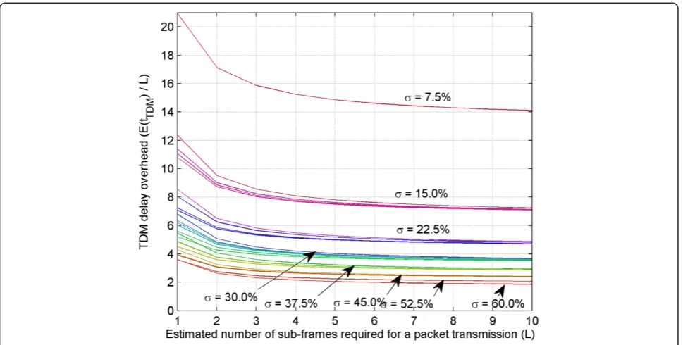
Comparison of the TDM delay overheads for various MBSFN configurations andLvalues is depicted in Figure 4. The TDM delay overhead is especially high in case of low
σ configurations. This relates to high waiting times be-tween the packet generation event and the first available BH sub-frame. Significance of this overhead is, however, decreasing with the expected number of active transmis-sion sub-frames L (i.e., with bigger data packets and/or lower data rates). This is because the t1Bh and tBh2Ac times are only applicable at the initial stage of a packet transmission.
In case of more than two-hop connection, the estima-tion of the TDM-related delay is less straightforward. This is because relations between the MBSFN configura-tions applied for two consecutive RN BH links need to be considered. The summary of expected values for the TDM-related delay for a tree-hop relaying is depicted in Figure 5. The depicted distributions are based on a stat-istical analysis of MBSFN sub-frame sequences with the assumption that all possible MBSFN configurations are equal probable.
Considering the typical values for the PDB require-ment (see Table 1), it should be stated that the MBSFN configurations with low σ are unable to satisfy the max-imum delay requirements. Highσ, configurations provide significantly higher probability of the PDB requirement satisfaction, however, still do not guarantee it. Basing on the presented estimations, it is recommended that the HD relaying should be used only in two-hop topologies, while the multi-hop topologies should be based on the FD relay-ing only (e.g., out-band [3,22]).
The lower bound delay values given above for both the FD and HD relay configurations related just to the na-ture of multi-hop transmission and the available RN configurations. In a realistic case of a network handling simultaneous transmissions of multiple users, the queuing delays will need to be added on top of the delays estimated in this section. Those delays, however, depend on the packet scheduling algorithm implemented in the BS and in the RNs. The aspect of proper design of this algorithm is treated in the following section.
Figure 4Expected TDM delay overhead for a two-hop relayed link for various MBSFN configurations.
4 QoS-aware resource management
In modern telecommunication networks, various service types may be used. This is a challenge for resource man-agement functionalities as the services may be character-ized with diverse QoS requirements. A feature of a good resource management algorithm should be to adapt its behavior the QoS requirement mixture present in the network at a given time. Examples of such algorithms for relay-less networks are described in [27,32,33].
One approach to the QoS-aware resource manage-ment problem is defined on the basis of the utility the-ory. The utility theory is a theory of economy that deals with wealth redistribution and trade. In the context of resource management, it is often considered as a method for optimizing resource allocation with respect to the user-perceived performance fairness. As such, it has been studiedinter alia by Fishburn [34,35], Kelly [36,37], and Lan [38-40].
In this section, firstly, the resource management framework based on the utility theory is described with the generic equations derived describing the procedure (Section 4.1). Secondly, the framework is adapted for the specific case of multi-hop transmissions (Section 4.2). Fi-nally, proposals of generic utility functions for various QoS-bounded traffic types are proposed (Section 4.3), and the overall resource management and scheduling metrics are derived for the traffic types (Section 4.4). The formulas describing the proposed resource manage-ment and scheduling procedure are defined here in a generic manner. Depending on specific QoS require-ments (GBR and delay) of a traffic type, one of the utility functions proposed in Section 4.3 can be used to calcu-late appropriate resource allocation and scheduling met-rics for the transmission.
4.1 Principles of utility theory
The system optimization with accordance to the utility theory is based on case-specific utility functions. The utility functions are a quantitative description of one’s preferences and satisfaction. In the field of telecommuni-cations, the preferences may reflect the QoS require-ments of a service. In such case, the utility functions represent the objective or subjective level of the user’s experience of using the network.
With respect to the above definition, each userjactive in a network can be characterized with a certain utility
ujrelated to its achieved performance. The achieved user performance is the outcome of the applied resource allo-cation schemex. In such case, the utility of the system is as follows:
USysð Þ ¼x X
j∈J
ujð Þx ð18Þ
where J is the set of active users, and USys is the utility of the whole system.
Target of the resource management optimization with respect to the utility theory is to find the resource allo-cation scheme x. that maximizes the cumulated system utility, i.e.,
where X is the set of all possible resource allocation schemes.
The optimization problem (19) can be solved, e.g., by means of the Lagrange multipliers method. The problem (19) is bounded with respect to the maximum resource availability
x¼ xj;r ⇔r∀∈R X
j∈J
xj;r≤1; ð20Þ
i.e., where the resource allocation scheme x can be de-fined as a set of factors xj,r, each denoting allocation of resource elementr(r∈R) to userj. When considering an instantaneous resource allocation, xj,r takes {0,1} values for allrandj.
The resource allocationx = {xj,r}has a direct impact on the transmission data rates of users by granting them ac-cess to channel capacities per resource element
yj¼ X
r∈R
Cj;rxj;r ð21Þ
where Cj,r is capacity of the radio link of the user j on the resource elementr.
Considering Equations (20) and (21), the Lagrange function for the problem (19) is as follows:
Lðy;x;z;λ;μÞ ¼ factor balancing inequality in Equation (20).
Solution to the problem (19) is a stationary point of the Lagrange function (22). To find it, partial derivatives of the Lagrange function (22) are calculated as follows:
∂L
and they are compared to zero, thus
λj¼
Based on the above equations, the following interpret-ation of the factorsλj,μr, andzrcan be stated:
λjis a marginal cost of utility, i.e., the price of changing value of the user’sjutility function. μris the systems cost of using resource elementr. zrindicates if the resource elementris available for
assignment (i.e., is not assigned to any of the users).
The above set of equations cannot be solved directly without using concrete utility functions for the users. A generic solution is to use an iterative resource allo-cation with priority metric Mjr derived by combining Equations (27) and (28)
Mj;r¼Cj;rλj¼Cjr
∂uj yj
∂yj ð31Þ
The priority metric indicates what increase of the user’s (and system’s) utility (aka the marginal utility [41]) can be expected when allocating resource elementrto userj.
Of course, the iterative implementation of the problem is sub-optimal. It is convergent to the optimal state, however, the resource allocation decisions are done in each iteration based on the past state of the system (λj) and estimates of the future state of the radio links (Cj,r). The optimality of the iterative implementation is as good as the knowledge of the conditions that will occur when the scheduled transmission will be executed. On the other hand, advantage of the iterative solution is the possibility of its direct implementation in a real system. The system can calculate the priority metric for each
user and resource and use it to assign resources for the next transmission time interval.
The above derivation corresponds to the optimization approach focused on the maximization of the system utility, i.e., the best effort (BE) approach. The approach allocates resources always to the user that can provide the highest marginal utility for the system. As a result, users in poor radio conditions (i.e., with low Cjr, e.g., at cell-edge) may never be granted resources. From an indi-vidual user perspective, such variation in the achievable performance indicates low reliability of the transmission quality and is typically inacceptable.
When performance fairness in the network is more de-sired than the total system performance, the so-calledα -fairness utility can be used. The α-fairness utility is a utility recalculation function that corresponds to a cer-tain fairness parameterα. Theα-fairness function is de-fined as [42] follows:
uα
Withα=1, theα-fairness optimal solution corresponds to the traditional proportional fair (PF) resource alloca-tion satisfying the Nash’s definition of fairness [43].
With respect to theα-fairness utility, the resource allo-cation priority metric can be redefined as the following:
Mα
jr¼Cjrλαj ¼Cjr uj α−2
∂uj yj
∂yj ð33Þ
whereλjαis theα-fair marginal cost of utility for the userj. Further in this paper, only the PF approach (α =1) is considered as the one providing significantly higher ubi-quity of performance compared to the BE approach.
4.2 Utility-based resource management for relaying
Systems enhanced with RNs can use a resource manage-ment approach similar to the one described in the previ-ous section. The utility-theory-based description of the optimization process can be extended over multi-hop con-nections, but additional constraints need to be introduced. The additional constraints correspond to the interdepend-encies of the consecutive relay links in a multi-hop con-nection. Specifically, the additional constraints are [29] the following:
The data rate on the RN BH should be equal to the
cumulated data rates on the RN AC links to users and to subordinate RNs
whereynBHis the BH data rate of the RNn,yj,nACis the data rate of user jon the AC of the RN n,yk,nBHis the BH data rate of a subordinate RNkconnected to the RN
n, andJnandNnare the sets of users and RNs connected to the RNn, respectively.
In case of HD RNs and FD RNs with frequency
domain resource partitioning, the same resources cannot be assigned to the BH and AC of an RN
xBH
n;rxACn;r ¼0;∀r∈R;n∈N ð35Þ
where xn,rBH and xn,rAC are the resource elementr allo-cation factors to BH and AC of the RN n, respectively, andRis the full set of system resources.
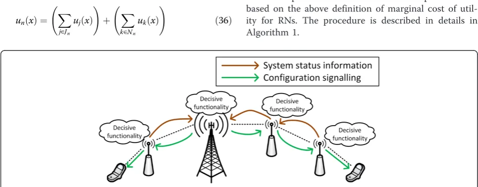
In the LTE-A standardization, the DF RNs are equipped with similar resource management capabilities as trad-itional BSs. This enables implementation of the distributed resource management schemes (see Figure 6). In this ap-proach, each access point (BS or RN) decides about the configuration of only the links it directly supports. Specif-ically, a BS controls resource allocation only to the direct links to users and first-hop RN BH. By analogy, a RN con-trols AC communication with the users connected to it and BH links of the next-hop RNs, if any. The distributed management scheme is based on local system status infor-mation, thus, in some cases may make sub-optimal deci-sions. It is, however, also significantly less burdened with the control information provisioning overheads.
With respect to the utility theory, the distributed re-source management process considers RNs as typical users. Based on Equation (34), the RN utility function can be defined as a combination of the utilities of the users connected to the RN, however, related to the RN BH link capacity, not their respective AC link capacities
unð Þ ¼x
The Lagrange function for the relay-enhanced network is thus
Again, solution to the optimization problem (19) can be found by calculating partial derivatives of the La-grange function (37) and comparing them to zeros (the derivation is to big extent the same as for relay-less net-work, thus, not repeated here). From the derivation, the PF marginal cost of utility for a RN is as follows:
λPF
and as in (31), the resource allocation priority metric for a RN (Mn,rPF) is
MPF
n;r¼Cn;rλPFn ð39Þ
Further in this paper, a distributed iterative resource allocation procedure is considered. The procedure is based on the above definition of marginal cost of util-ity for RNs. The procedure is described in details in Algorithm 1.
4.3 Proposal of utility function for real-time traffic
In the state-of-the-art literature, various proposals of utility functions can be found. The described utility functions are, however, not always realistic. For example, it is often forced to make the utility functions concave to guarantee that there always is a unique solution to the resource assignment optimization problem. In this section, the utility functions for real-time services are proposed with consideration of the standardized QoS requirements defined in [26] (see also Table 1).
As explained in Section 2, the two main QoS require-ments for real-time traffic are the GBR and PDB. A utility function for a real-time traffic should, therefore, reflect the two requirements and, thus, it is proposed here to be formulated as
ujð Þ ¼x wjuGBRj yj uPDBj tj ð40Þ
whereyjis the data rate of the userj,tjis its packet de-livery time, ujGBR is the utility related to the GBR re-quirement satisfaction, ujPDB is the utility related to the PDB requirement satisfaction, and wj is priority weight of the service type related to the GBR of the service.
With respect to the resource allocation scheme x, the formula (40) is subject to Equation (21) and
E tj ¼S=yj ð41Þ
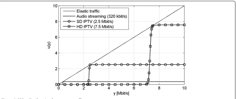
In case of a GBR traffic as, e.g., audio and/or video live streaming, data is consumed by the receiving application at a specific rate matching the rate in which the data is generated by the source application. If the available transmission data rate is above the data generation rate,
the excessive link capacity will be unused and the utility of the transmission will not increase above a certain maximum level. On the other hand, if the available transmission data rate is below the data generation rate at the source application, the target application will show loss of data, e.g., breaks in audio/video streaming. Therefore, the GBR utility function should have a form of a step function, with the step steepness depending on the acceptable level of packet loss. In line with this char-acteristic, it is proposed here to define the GBR utility function as the following modified logistic function:
uGBR
j yj ¼
1
1þ exp a
GBR
j −yj
bGBR
ð42Þ
where ajGBR is a parameter related to the GBR value of service used by the user j, and bGBR is a parameter con-trolling the steepness of the GBR utility function in proximity of yj= ajGBR. The shape of the GBR utility function and its PF modification for various traffic types are depicted in Figure 7.
wait in the application buffer and not increase the QoS. A function meeting this description is as follows:
uPDB
j tj ¼
1−exp −t
Max
j −tj
bPDB
1þ exp −t
Max
j −tj
bPDB
ð43Þ
wheretjMaxis the maximum packet delivery time for the userj, andbPDBis a parameter controlling the steepness of the PDB utility function. Impact of the PDB utility on the overall utility function for real-time traffic is illus-trated in Figure 8.
4.4 Packet scheduling algorithms
Based on the above proposed utility functions for real-time traffic, resource management can be done in a cellu-lar system in a QoS-aware manner. Next, several options for the QoS-aware resource allocation are defined. The ap-proaches differ in terms of the criteria they aim at optimizing.
4.4.1 GBR-aware scheduling
The basic and the most common approach to resource management considers only optimization with respect to the required data rates. The GBR-aware scheduling
Figure 7GBR utility function for common traffic types.
algorithm tries to achieve a certain distribution of data rates to users with respect to their requirements. With respect to the utility theory framework described earlier, by inputting the GBR utility function to the general formula for the PF marginal cost of utility, the GBR-aware marginal cost of utility for the PF resource management is as follows:
λGBR
and next by solving the derivative in (44) with respect to (42), there is
In case of traffic with specified requirements on the max-imum packet delivery time, the PDB-aware scheduling al-gorithm can be used. The PDB-aware resource allocation prioritizes the delay optimization criteria; however, it also considers the minimum data rate requirement. This is be-cause, as stated earlier, it is not possible to provide stable PDB satisfaction without satisfaction of the minimum data rate. By inputting the PDB utility function to the general formula for the PF marginal cost of utility, the PDB mar-ginal cost of utility for the PF resource management is
λPDB
where considering the transmission and queuing times
tj¼yS j
þtq;j ð47Þ
thus, by solving the derivative in (46) with respect to (43), there is
4.4.3 Full QoS-aware scheduling
In the most complex approach, radio resources are assigned with respect to both the GBR and PDB require-ments. In this case, the marginal cost of utility is calcu-lated as the combination of the formulas (45) and (48)
λQoS
j ¼λGBRj þλPDBj ð49Þ
5 Performance evaluation
This section covers simulation-based evaluations of the concepts described in the former sections of this paper. Firstly, simulation assumptions used for the analysis are described. Later, the generated results are presented and discussed.
5.1 Simulation assumptions
The data presented further in this paper is generated via computer simulations based on the widely accepted methodology for the LTE system evaluations specified by the 3GPP forum in [3]. For aspects not covered by the 3GPP recommendation (e.g., multi-hop relaying), sup-plementary assumptions are taken from [44].
The tool used to perform the evaluations presented further in this paper is a dynamic system level simula-tor created by the author on the MATLAB platform. It models operation of an LTE-A network including layers 1 to 3 of the protocol stack. All relevant network nodes (BSs, RNs, and UEs) and radio interfaces are modeled explicitly. The modeling is dynamic, which means that there is a timeline simulated that drives dy-namic mechanisms such as user mobility, fast fading, resource allocation, traffic dynamics (data packets cre-ation, transmission, reception and dropping), etc. Op-eration of the tool has be verified and calibrated vs. multiple other similar tools as part of the European Union founded project ARTIST4G [44].
The simulation assumptions that are clearly defined in [3] and [44] (e.g., radio propagation and network node models) are not repeated here as the two documents are publically available. With respect to the parameters that are ambiguous in [3] and [44], in this paper, it is specific-ally assumed that
Only downlink transmission direction is simulated.
Total system bandwidth is 20 MHz with full
resource reuse at each cell.
Macro BSs are deployed on a hexagon grid with
1,732 m inter-site distance (ISD).
In relay-enhanced network scenarios, ten RNs are
used per macro BS sector. The RNs are deployed in two tiers along the edges of macro sectors (for details, see [44]).
RNs utilize the standardized LTE cell-selection
procedure [45] (i.e., based on the higher received signal power) to select their respective donor cells. The selection is, however, restricted with respect to the capability of forming multi-hop topologies. The multi-hop topology support is a parameter of the simulations.
MBSFN configuration for HD RNs is adapted to
provide BH/AC capacity balancing [27] (typically
patterns with low BH sub-frame concentration are used where possible.
Users are deployed uniformly in each macro BS
sector, and they utilize the LTE cell selection procedure to attach to BSs or RNs.
The assumptions defined explicitly for this paper cover also traffic models. Specifically, two scenarios are as-sumed here: low and high load. In the low load scenario, there are on average ten users per macro BS sector, and in the high load scenario, the average number of users per sector is 20. In both load scenarios, it is assumed that all users use constant bit-rate real-time traffic ser-vices with the following distribution:
Two thirds of all users request an audio streaming
transmission with 320 kbit/s GBR, and
One third of all users request a standard definition (SD) IP television (IPTV) transmission with 2.5 Mbit/s GBR.
For all considered traffic types, the additional assump-tions are as follows:
Data packet size is 1,374 bytes [46], and
Maximum packet delivery time in radio interface is
130 ms (150 ms PDB with 20 ms delay assumed for core network [26]).
All the users are active all the time continuously gen-erating data packets according to their respective service data rates and packet sizes.
The traffic assumptions correspond to the following average load conditions:
Low load scenario:
Relay-less system: 75% load Relay-enhanced system: 50% load
High load scenario:
Relay-less system: 95% to 100% load Relay-enhanced system: 80% load
With respect to the assumed traffic types, the system efficiency is assessed in terms of the following:
GBR satisfaction, i.e., ratio between the data rate achieved by a user and its GBR setting,
Packet dropping rate (PDR), i.e., percentage of packets that are not fully delivered to the target user within the 120 ms time limit, and
Average and guaranteed (i.e., 95th percentile) packet delivery times.
5.2 Results and discussion
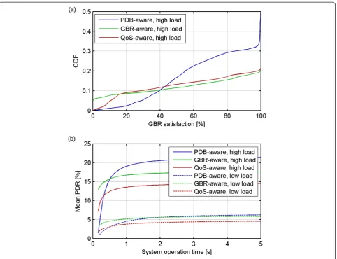
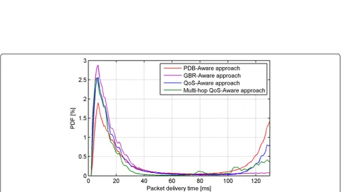
In Section 4.4, three approaches to resource management are proposed. Those management schemes are compared next on the basis of relay-less and relay-enhanced net-works. Figure 9 depicts statistics of the GBR satisfaction and average packed drop rate (PDR) for macro BS con-nected users in a relay-less system. Figure 10, on the other hand, presents the distributions of the packet delivery times for the relay connected users in the presence of a three-hop HD relaying topology.
The PDB-aware scheduling focuses on satisfying the packet delivery time requirement for all users resulting in the lowest PDR at the initial stage of the system oper-ation (see Figure 9b). The approach, however, does not consider directly the data rate requirement, thus it pro-vides relatively low GBR satisfaction (on average 84% in the high load scenario). As result, many users do not achieve their required minimum data rate (even in the low load scenario). For such users, the PDR increases significantly over time (up to average 6% PDR in the low load scenario and 21% PDR in the high load scenario). As illustrated in Figure 10, the PDB-aware scheduling tries to deliver as many packets as possible by increasing scheduling priority for the packets with short times to drop (visible as increased probability for the highest packet delivery times). The actions are, however, insuffi-cient considering the unsatisfied GBR requirement.
The GBR-aware approach, on the other hand, focuses on satisfying the data rate requirement and does not consider the packet delivery time requirement. This ap-proach results in higher average GBR satisfaction level (88% in the high load scenario) and improved long-term PDR statistics (on average 5.5% PDR in the low load sce-nario and 17.5% PDR in the high load scesce-nario). The ap-proach, however, does not take any actions with respect to the packets with short times to drop (see right-hand part of Figure 10), thus some packets are dropped even though they could be delivered on time.
Finally, the full QoS-aware approach considers both the GBR and PDB requirements. Such dual approach re-sults in the highest performance statistics. In terms of the GBR satisfaction, it provides similar average satisfac-tion as the GBR-aware approach (87% in the high load scenario) but improved performance for users in the worst traffic conditions (10% gain at 5th percentile GBR satisfaction level). It terms of the PDB requirement, it also results in the lowest PER levels (on average 4.5% PDR in the low load scenario and 14% PDR in the high load scenario).
proportionally to the number of end-to-end relaying hops. Specifically, in the conducted simulations, it is as-sumed that the maximum packet delivery time for a hop h in an H-hop connection is
tMax
j;h ¼tMaxj −H−hH 30 ms ð50Þ
The purpose of the modification is to improve the on-time packet delivery for the relay-connected users. The ef-fect of the modification is illustrated in Figure 10. Trans-missions to users connected over three-hop and two-hop relaying connections have distinctive peaks in packet de-livery times at 80 and 110 ms, respectively. The peaks cor-respond to the reduced maximum packet delivery times of 70 and 100 ms, respectively. As a result, the average PDR for the relay-connected users is reduced from 16% when using the basic QoS-aware approach to 14% PDR when using the multi-hop QoS-aware approach.
Basing on the data presented in Figures 9 and 10, it can be concluded that the joint GBR- and PDB-aware
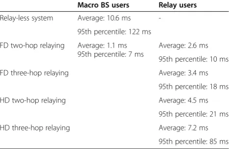
approach is the most effective in providing the overall satisfaction for users using real-time traffic. This method is used next, to analyze packet delivery times for various relaying topologies. Specifically, delays related to the FD and HD RN operations in two- and three-hop topologies are compared. In this analysis, only the low load sce-nario is considered as it gives a clear picture of the relaying-originated delays without the impact of macro BS overload. Figure 11 depicts distributions of packet delivery times for the considered scenarios and corre-sponding statistics are summarized in Table 2.
The packet delivery time statistics confirms the ana-lysis conducted in Section 3. The FD relaying has a minor impact on the end-to-end delay. On average, the FD two-hop relaying generates 1.5 ms additional delay. The FD three-hop relaying introduces on average 2.3 ms additional delay, however, it also increases the maximum delay by 11 ms (compared to 7 ms for macro BS-connected users). The results are in line with the analysis included in Section 3.1 and especially with formula (4).
Figure 11Packet delivery times for low load relaying scenarios.
In case of HD relaying, the impact on packet delivery times is higher than in case of FD relaying. The average packet delivery time for two-hop relaying is 4.5 ms and for three-hop relaying, it is 7.2 ms. Again, the simulation results are in line with theoretical predictions presented in Figures 4 and 5 (see results for highσandL=1). In case of HD relaying, the highest delays are significantly in-creased in comparison to the direct BS-user transmission (up to 85 ms in case of three-hop connection). This indi-cates that in case of bigger packet sizes and/or lower data rates available for the multi-hop connection, problems with satisfying the packet delivery time might occur on wide scale even for users with satisfied GBR requirement.
6 Conclusions
This paper deals with the topic of satisfying packet deliv-ery time requirement for multi-hop relayed transmis-sions. The issue is a highly relevant topic in the context of recent development of cellular systems. This is be-cause the relaying concept is included in the standards of fourth generation systems; however, the relevant standardization bodies do not provide dedicated mecha-nisms for QoS provisioning over relayed links.
The presented discussion of the topic focuses first on the analysis of the two available relaying configurations: full-duplex and half-duplex operation. The full-duplex relaying is characterized with a small additional delay overhead related to the RN processing time. The theor-etical analysis and the conducted simulations show that the lower bound of the additional delay is in the range of few milliseconds and proportional to the number of transmission hops. The statistically highest delays are, however, more than doubled when comparing a three-hop FD topology with a direct BS-user transmission.
The relaying delay overhead is a more significant issue in case of HD RNs. In this case, the delay depends strongly on the configuration of time-domain multiplex-ing of RN BH and AC sub-frames. In the worst case, the
end-to-end transmission time over an FD two-hop con-nection can be even 20 times higher than for the direct connection. The situation can be, however, improved with proper sub-frame configuration.
In the second part of this paper, resource management schemes based on the utility theory are proposed for managing relay-enhanced networks. The proposed con-cepts take into consideration the minimum data rate and/ or the maximum packet delivery times to provide QoS sat-isfaction for users. From the considered schemes, the one based on a complex data rate and transmission time shows to provide the best results. The scheme can be further optimize for operation over multi-hop relayed links.
The overall conclusions from the study are that the full-duplex relaying is characterized with significantly lower delay overheads than the half-duplex relaying, and thus the full-duplex relaying is generally recommended. As for the half-duplex relaying, it is recommended to be used with sub-frame configurations characterized with high percentage of time available for backhaul link oper-ation and low concentroper-ation of the backhaul sub-frames. It is also recommended to use the half-duplex relaying only with low number of end-to-end hops (maximum of three).
Competing interests
The author declares that he has no competing interests.
Acknowledgement
The author is a scholar within Sub-measure 8.2.2 Regional Innovation Strategies, Measure 8.2 Transfer of knowledge, Priority VIII regional human resources for the economy, Human Capital Operational Programme co-financed by European Social Fund and state budget.
Received: 1 February 2013 Accepted: 13 October 2014 Published: 29 October 2014
References
1. ITU-R,M.2134 Requirements Related to Technical Performance for IMT-Advanced Radio Interface(s)(2008)
2. 3GPP,TR 36.814 v9.0.0: Evolved Universal Terrestrial Radio Access (E-UTRA); Further advancements for E-UTRA physical layer aspects(2010)
3. H Holma, A Toskala,LTE for UMTS: Evolution to LTE-Advanced, 2nd edn. (John Wiley & Sons, Chichester (UK), 2011)
4. WiMAX Forum,WMF-T23-005-R020v01: Mobile Radio Specifications; Release 2.0
(2012)
5. WiMAX Forum,WiMAX and the IEEE 802.16m Air Interface Standard(2010) 6. S Parkvall, E Dahlman, A Furuskär, Y Jading, M Olsson, S Wänstedt, K Zangi,
LTE-Advanced - Evolving LTE Towards IMT-Advanced, inIEEE Vehicular Technology Conference (VTC). Fall(2008), pp. 1–5
7. PE Mogensen, T Koivisto, KI Pedersen, IZ Kovács, B Raaf, K Pajukoski, MJ Rinne, LTE-Advanced: The Path Towards Gigabit/S in Wireless Mobile Communications, inInternational Conference on Wireless Communication, Vehicular Technology, Information Theory and Aerospace & Electronic Systems Technology (Wireless VITAE)(2009), pp. 147–151
8. Q Li, G Li, W Lee, M Lee, D Mazzarese, B Clerckx, Z Li, MIMO techniques in WiMAX and LTE: a feature overview. IEEE Commun Mag48(5), 86–92 (2010) 9. KI Pedersen, C Rosa, H Nguyen, LGU Garcia, Y Wang, Carrier aggregation for
LTE-Advanced: functionality and performance aspects. IEEE Commun Mag
49(6), 89–95 (2011)
10. K Safjan, S Strzyż, J Góra, Kontrola interferencji oraz poprawa wydajności heterogenicznych sieci LTE. Przegląd Telekomunikacyjny Wiadomości Telekomunikacyjne2011(6), 1–4 (2011)
Table 2 Summary of packet delivery statistics for macro BS and relay-connected users in the low load scenario
Macro BS users Relay users
Relay-less system Average: 10.6 ms
-95th percentile: 122 ms
FD two-hop relaying Average: 1.1 ms 95th percentile: 7 ms
Average: 2.6 ms
95th percentile: 10 ms
FD three-hop relaying Average: 3.4 ms
95th percentile: 18 ms
HD two-hop relaying Average: 4.5 ms
95th percentile: 21 ms
HD three-hop relaying Average: 7.2 ms
11. N Gresset, H Halbauer, J Koppenborg, W Zirwas, H Khanfir, Interference avoidance techniques: improving ubiquitous user experience. IEEE Veh Technol Mag7(4), 37–45 (2012)
12. R Irmer, H Droste, P Marsch, M Griger, G Fettweis, S Brueck, HP Mayer, L Thiele, V Jungnickel, Coordinated multipoint: concepts, performance and field trial results. IEEE Commun Mag49(2), 102–111 (2011)
13. R Irmer, F Diehm, On Coverage and Capacity of Relaying in LTE-Advanced in Example Deployments, inIEEE International Symposium on Personal, Indoor and Mobile Radio Communications (PIMRC)(2008), pp. 1–5 14. T Beniero, S Redana, J Hämäläinen, B Raaf, Effect of Relaying on Coverage in
3GPP LTE-Advanced, inIEEE Vehicular Technology Conference (VTC)(Spring, 2009), pp. 1–5
15. Y Sui, A Papadogiannis, T Svensson, The Potential of Moving Relays - a Performance Analysis, inIEEE Vehicular Technology Conference (VTC)(2012), pp. 1–5
16. E Lang, S Redana, B Raaf, Business Impact of Relay Deployment for Coverage Extension in 3GPP LTE-Advanced, inIEEE International Conference on Communications (ICC) Workshops(2009), pp. 1–5
17. A Bou Saleh, S Redana, B Raaf, J Hämäläinen, Comparison of Relay and Pico Enb Deployments in LTE-Advanced, inIEEE Vehicular Technology Conference (VTC)(2009), pp. 1–5
18. 3GPP, RP-110911,Relays for LTE - Core Part (3GPP Work Item Description)
(2011)
19. A Bou Saleh, Ö Bulakci, J Hämäläinen, S Redana, B Raaf, Analysis of the impact of site planning on the performance of relay deployments. IEEE Trans Veh Technol61(7), 3139–3150 (2011)
20. O. Bulakci, S. Redana, B. Raaf, J. Hämäläinen, Performance Enhancement in LTE-Advanced Relay Networks Via Relay Site Planning, inIEEE Vehicular Technology Conference (VTC)(Spring, 2010), pp. 1–5
21. ARTIST4G WP3, D3.3,Relay Networks Specific Resource Management Features
(2011)
22. ARTIST4G WP3, D3.4,Relay Configurations(2011)
23. 3GPP, TS 36.806 v9.0.0,Evolved Universal Terrestrial Radio Access (E-UTRA); Relay Architectures for E-UTRA (LTE-Advanced)(2010)
24. ARTIST4G WP3, D3.5a,Enhancements to Type-1 Relay Implementation(2012) 25. 3GPP, TS 36.216 v10.3.1,Evolved Universal Terrestrial Radio Access (E-UTRA);
Physical Layer for Relaying Operation(2011)
26. 3GPP, TS 23.203 v11.7.0,Policy and Charging Control Architecture(2012) 27. B Sadiq, R Madan, A Sampath, Downlink Scheduling for Multiclass Traffic in
LTE, inEURASIP Journal on Wireless Communications and Networking(2009), pp. 1–18
28. F Vitiello, T Riihonen, J Hämäläinen, S Redana, On Buffering at the Relay Node in LTE-Advanced, inIEEE Vehicular Technology Conference (VTC)(2011), pp. 1–5
29. J Góra, S Redana, Resource Management Issues for Multi-Carrier Relay-Enhanced Systems, inEURASIP Journal on Wireless Communications and Networking(2012), pp. 1–8
30. T Riihonen, S Werner, R Wichman, ZB Eduardo, On the Feasibility of Full-Duplex Relaying in the Presence of Loop Interference, inIEEE Workshop on Signal Processing Advances in Wireless Communications (SPAWC)(2009), pp. 275–279
31. H Holma, A Toskala,LTE-Advanced 3GPP Solution for IMT-Advanced, 1st edn. (John Wiley & Sons, Chichester (UK), 2012), pp. 1–223
32. J Huang, VG Subramanian, R Agrawal, R Berry, Downlink scheduling and resource allocation for OFDM systems, inProc. of the Conference on Information Sciences and Systems (CISS)(2006)
33. R Agarwal, V Majjigi, R Vannithamby, JM Cioffi, Efficient Scheduling for Heterogeneous Services in OFDMA Downlink, inProc. of the IEEE Global Telecommunications Conference (GLOBECOM)(2007), pp. 3235–3239 34. PC Fishburn,Utility theory for decision making(John Wiley & Sons, Chichester
(UK), 1970), pp. 1–246
35. PC Fishburn, Utility theory, INFORMS Manage. Sci Theory Series
14(5), 335–378 (2010)
36. F Kelly, Charging and rate control for elastic traffic. Eur Trans Telecommun
8(1), 33–37 (1997)
37. FP Kelly, AK Maulloo, DKH Tan, Rate control for communication networks: shadow prices, proportional fairness and stability. J Oper Res Soc
49(3), 237–252 (1998)
38. T Lan, D Kao, M Chiang, A Sabharwal, An Axiomatic Theory of Fairness In Network Resource Allocation, inIEEE International Conference on Computer Communications (INFOCOM)(2010), pp. 1–9
39. T Lan, M Chiang, An Axiomatic Theory of Fairness in Resource Allocation, in
IEEE International Conference on Computer Communications (INFOCOM)
(2010), pp. 1–9
40. C Joe Wong, S Sen, T Lan, M Chiang, Multi-Resource Allocation: Fairness-Efficiency Tradeoffs in a Unifying Framework, inIEEE International Conference on Computer Communications (INFOCOM)(2012), pp. 1206–1214
41. L Rittenberg, T Tregarthen,Principles of Microeconomics(Flat World Knowledge, Inc, Washington, D.C. (USA), 2009), pp. 1–432
42. M Uchida, J Kurose, An Information-Theoretic Characterization of Weighted Alpha-Proportional Fairness, inIEEE International Conference on Computer Communications (INFOCOM)(2009), pp. 1053–1061
43. J Nash, The bargaining problem. Econometrica18(2), 155–162 (1950) 44. ARTIST4G WP3, D3.5,Performance Evaluations of Advanced Relay Concepts
(2012)
45. 3GPP, TS 36.300 v11.3.0,Evolved Universal Terrestrial Radio access (E-UTRA) and Evolved Universal Terrestrial Radio access Network (E-UTRAN); Overall Description; stage 2(2012)
46. G Thompson,IPTV - What does it really mean and how does it work? SMPTE [Online(2013). Available at http://www.smpte-profdev.org/resources/ SMPTE_PDA_Now_01-17-2008_IPTV.pdf Accessed 13 Jan
doi:10.1186/1687-1499-2014-178
Cite this article as:Góra:QoS-aware resource management for LTE-Advanced relay-enhanced network.EURASIP Journal on Wireless Communications and Networking20142014:178.
Submit your manuscript to a
journal and benefi t from:
7 Convenient online submission
7 Rigorous peer review
7 Immediate publication on acceptance
7 Open access: articles freely available online
7 High visibility within the fi eld
7 Retaining the copyright to your article