ISSN(Online): 2319-8753
ISSN (Print): 2347-6710
I
nternational
J
ournal of
I
nnovative
R
esearch in
S
cience,
E
ngineering and
T
echnology
(An ISO 3297: 2007 Certified Organization)
Vol. 4, Issue 6, June 2015
AGC of A Gas-Thermal System with ESD
Units
R.Senthilkumar , PiyushRai, Megha Katiyar
Assistant Professor (O.G), Department of EEE, SRM University, Kattankulathur, Kancheepuram, Tamil Nadu, India
B.Tech, Department of EEE, SRM University, Kattankulathur, Kancheepuram, Tamil Nadu, India
B.Tech, Department of EEE, SRM University, Kattankulathur, Kancheepuram, Tamil Nadu, India
ABSTRACT: In this paper, automatic generation control (AGC) of two area interconnected power system having diverse sources of power generation is studied. All the power generation units from different sources are equipped with speed governors. A continuous time transfer function model of the system for studying dynamic response for small load disturbances is presented. In general the proportional -integral-derivative (PID) are used but in this work we have the fuzzy logic automatic generation as control scheme applied to the sources and power generation from the source is allowed to operate at its scheduled level with only speed governor control. Whereas the effect of the external energy storage devices that may help the AGC to work in more optimal way so the part of the frequency deviation is rectified with a very quick time response.
KEYWORDS: PID Controller, CES, SMES, Fuzzy Controller
I. INTRODUCTION
Power systems consist of control areas representing a coherent group of generators i.e. generators which swing in unison characterized by equal frequency deviations. In addition to their own generations and to eliminate mismatch between generation and demand these control areas are interconnected through tie-lines for providing contractual exchange of power under normal operating conditions. One of the control problems in
power system operation is to maintain the frequency and power interchange between the areas at their rated values.
Many articles are reported [2]-[6] demonstrating the use of SMES unit for the improvement of transient stability. SMES is controlled through conventional controllers in most of these works. The power system stability is mainly dependent on the appropriate control strategy of SMES. Though many SMES control strategies [2]-[6] are proposed in the literature, the real problem is the determination of the best or optimal switching strategies.
ISSN(Online): 2319-8753
ISSN (Print): 2347-6710
I
nternational
J
ournal of
I
nnovative
R
esearch in
S
cience,
E
ngineering and
T
echnology
(An ISO 3297: 2007 Certified Organization)
Vol. 4, Issue 6, June 2015
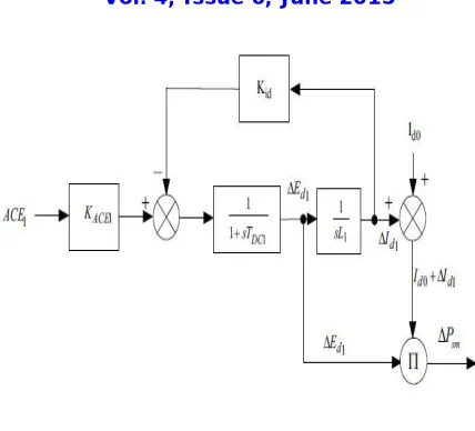
Fig 1: Two Area Gas-Thermal System
II. GAS-THERMAL POWER SYSTEM MODEL
Electric power systems are complex, nonlinear dynamic system. The load frequency controller controls the control valves associated with High Pressure (HP) turbine at very small load variations. The model of a two-area power system suitable for a digital simulation of AGC is developed for the analysis as shown in Fig. 1. Two areas are connected by a weak tie-line. When there is sudden rise in power demand in one area, the stored energy is almost immediately released by the SMES and CES through its power conversion system. As the governor control mechanism starts working to set the power system to the new equilibrium condition, the SMES coil stores energy back to its nominal level whereas a similar action happens with the CES model. This action also happens when there is a sudden decrease in load demand.
III. CAPACITIVE ENERGY STORAGE
Super capacitors, also known as electrical double-layer capacitor, ultra capacitor, are new energy storage devices that close the gap between aluminium electrolytic capacitors and batteries in terms of power and energy density [2]. Its capacity ranges from several farads to tens of thousands farads and its power density is 10 times more than battery’s. The storage capacity of super capacitor is higher than electrolytic capacitor, and it has wide working temperature range, rapid charging and discharging, long cycle life, no pollution and emission and so on[3-5]. This makes them ideal for all applications requiring high peak power discharge for a few milliseconds up to several minutes’ conditions.
ISSN(Online): 2319-8753
ISSN (Print): 2347-6710
I
nternational
J
ournal of
I
nnovative
R
esearch in
S
cience,
E
ngineering and
T
echnology
(An ISO 3297: 2007 Certified Organization)
Vol. 4, Issue 6, June 2015
the power shortage in order to stabilize and smooth the voltage fluctuations. Similar is the action during sudden release of loads. The capacitor is charged immediately towards its full value, thus absorbing some portion of the excess energy in the system and as the system returns to its steady state, the absorbed excess energy is released and the capacitor voltage attains its normal value.
Figure 2. CES Unit: Block diagram representation with formulation
IV. SUPER MAGNETIC ENERGY STORAGE
ISSN(Online): 2319-8753
ISSN (Print): 2347-6710
I
nternational
J
ournal of
I
nnovative
R
esearch in
S
cience,
E
ngineering and
T
echnology
(An ISO 3297: 2007 Certified Organization)
Vol. 4, Issue 6, June 2015
Fig.3: SMES Block diagram
V. DYNAMIC MODEL OF SSSC
The linearized model of a two area interconnected system [3] including the dynamic of SSSC is shown in Fig. 4, where the dynamics of governor systems in both areas are eliminated. Power output of SSSC (Pssc), therefore, flows into both areas withdifferent signs (+, -), simultaneously. In the presence of SSSC between areas 1 and 2, active power flow deviation between areas 1 and 2 can be expressed as follow [3, 6]:
P12 = Ptie−12 + PSSSC
Where ΔPtie-12 is tie-line power flow deviation between areas 1and 2 without SSSC, and ΔPSSSC is active power flow deviation between areas 1 and 2 due to SSSC. ΔPSSSC flows into both areas 1 and 2 with different signs (+ and -) dynamically [3, 6].
Linearized model of SSSC and its active power controller are shown in Fig. 4. As shown in Fig. 4, SSSC is a MIMO system. Active power controller of SSSC, i.e. KC(s) consists of a lead/lag compensator, a High Pass Filter (HPF) and a controller gain [3, 4]. Transfer function of active power controller of SSSC can be expressed as follow:
ISSN(Online): 2319-8753
ISSN (Print): 2347-6710
I
nternational
J
ournal of
I
nnovative
R
esearch in
S
cience,
E
ngineering and
T
echnology
(An ISO 3297: 2007 Certified Organization)
Vol. 4, Issue 6, June 2015
VI. THE PROPOSED FUZZY GAIN SCHEDULED PID (FGSPID) CONTROLLER
The general practice in the design of a LFC is to utilize a PI and PID controllers. A typical conventional PID control system this gives adequate system response considering the stability requirements and the performance of its regulating units. In this case the response of the PI and PID controller is not satisfactory enough and large oscillations may occur in the system [8-9]. For that reason, a fuzzy PID controller is designed and implemented in this study. The AGC based on FLC is proposed in this study. One of its main advantages is that controller parameters can be changed very quickly by the system dynamics because no parameter estimation is required in designing controller for nonlinear system.
Besides being an effective technique to compensate for non-linear and other predictable variations in the system dynamics, it is also easier to implement. The gain scheduling in this study is done based on the frequency deviation step response of the system for different values of Kp , Ki , Kd with 0.01 p.u.MW step load change in area-1. As a higher value of Ki results in reduction of maximum deviation of the system frequency but the system oscillates for little longer times, whereas lower values of Ki yield comparatively higher maximum frequency deviation at the beginning but provide effective damping in the later cycles.
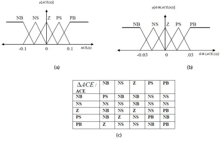
In Figure , NB, NS, Z, PS, and PB are the linguistic terms that represent negative big, negative small, zero, positive small, and positive big respectively. The bisector of area method was used for defuzzification. The control rules for the proposed controller are very straightforward and have been derived from the viewpoint of practical system operation using trial and error methods. The fuzzy rules, as used in our study, for the FGSPID controller, are given in Table I. In the present study, dynamic response was further investigated with modified ACE as the input signal to the FGSPID controller.
(a) (b)
(c)
ISSN(Online): 2319-8753
ISSN (Print): 2347-6710
I
nternational
J
ournal of
I
nnovative
R
esearch in
S
cience,
E
ngineering and
T
echnology
(An ISO 3297: 2007 Certified Organization)
Vol. 4, Issue 6, June 2015
VII. SIMULATION RESULTS
In this control scheme ie;(PID + SSSC WITH VARIOUS EDS) that determines the various conditionsfor handling through the frequency deviation.
The following paper mainly focuses on the Gas aspect, As per the previous years’ work we had only the installation of the particular systematic Energy storage devices were installed but in this work a clear study after the implementation of the particular SSSC i.e.; basically a fact device which plays a role of Frequency stabilization
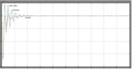
Fig 6: Frequency deviation at area1 at conventional methods.
Fig 7: Frequency deviation at area1 with SSSC implementation.
As per the above graphical representation i.e.; Fig 6.the conventional methodology is followed trough to determine values of the best control strategy. The tabulation shows the particular rise time which states the main theme of stabilization.
ISSN(Online): 2319-8753
ISSN (Print): 2347-6710
I
nternational
J
ournal of
I
nnovative
R
esearch in
S
cience,
E
ngineering and
T
echnology
(An ISO 3297: 2007 Certified Organization)
Vol. 4, Issue 6, June 2015
GAS Settling Rise Peak Over
POWER Time Time shoot
PLANT
I Cont 4.14 0.599 1.05 5.12
PI Cont 6.03 2.83 1 0
PID Cont 4.7 1.94 0.99 0
9
I + CES 20.8 1.68 1.01 1.07
PI + CES 4.59 0.287 1.29 29.5
PID+CES 0.196 0.022 1.12 12.4
I+SMES 4.92 0.293 1.79 78.8
PI+SME 0.9 0.112 1.06 5.87
S
PID+ 0.369 0.011 1.09 9.23
SMES
I+SSSC 1.38 5.7 2.36 1.02
PI+SSSC 0.597 5.14 6.19 1.06
PID+ 0.575 5.61 8.35 1.08
SSSC
ICont+C 1.17 21.6 11.3 1.11
ES+SSS C
PICont+ 0.304 74.6 68.3 1.68
CES+SS SC
PIDCont 0.0045 0.0657 12.6 1.13
+CES+S SSC
I+SMES 2.48 16.1 1.47 1.01
+SSSC
PI+SME 0.0775 0.867 13.9 1.14
S+SSSC
PIDCont 0.0443 0.706 12.2 1.12
ISSN(Online): 2319-8753
ISSN (Print): 2347-6710
I
nternational
J
ournal of
I
nnovative
R
esearch in
S
cience,
E
ngineering and
T
echnology
(An ISO 3297: 2007 Certified Organization)
Vol. 4, Issue 6, June 2015
As per the result found out determine the state that which has the criteria varying in each and every data whereas the part of I controller as the best output which has arise time of 4.14 secs.
Well then entering in to the installation of the EDS give the implementation value of the particular PID where Proportionality and the derivative control strategy is also required.
PID Control with CES having a Rise time 0.196secs whereas after adding up the SSSC 0.00459secs. But while implementation of only SSSC the time taken 0.369secs which states that CES is one of the cheapest type of implementing the particular format.
Well the part SMES states that it’s not faster i.e.; 0.575secs which is better than the conventional but slower than CES devised system. Whereas the SSSC when added it takes only 0.0443secs which states that the system is much faster than the previous stimulations.
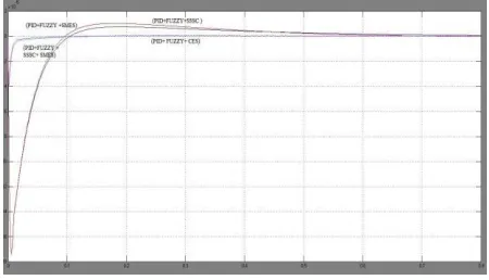
Fig 8: Frequency deviation at area1 with Fuzzy logic.
The particular fuzzy tabulation states that the FPID is one of the best methods of improving the particular stabilization in more optimal way. As per our Research we found out that the PID controller where the best in case of including the FACTS devices without any Energy storage devices. So we took the best conventional output to implement the fuzzy logic control scheme.
As the FPID logic controller gave an output which were very much satisfying with one of the most quick and optimal way of carrying out the Frequency stabilization. The similar studies are carried out in Thermal plant whereas we have focused more on the Gas since it is a new form of implementation these control strategies.
GAS POWER Settling Rise Peak Overshoot
PLANT Time Time
I+ Fuzzy 2.06 4.87 0 0.999
PID+Fuzzy+CES 0.004 0.35 14 1.14
PID+Fuzzy+SMES 0.00098 0.118 18.7 1.18
ISSN(Online): 2319-8753
ISSN (Print): 2347-6710
I
nternational
J
ournal of
I
nnovative
R
esearch in
S
cience,
E
ngineering and
T
echnology
(An ISO 3297: 2007 Certified Organization)
Vol. 4, Issue 6, June 2015
I +Fuzzy+SSSC 1.34 2.36 1.22 1.01
PID+Fuzzy+SSSC+ 0.00403 2.93 14.4 1.14
CES
PID+Fuzzy+SSSC+ 0.00082 0.982 1.82 1.18
SMES
Thermal POWER Settling Rise Peak overshoot
PLANT Time
Time
I+Fuzzy 2.86 5.69 0 0.999
PID+Fuzzy+CES 0.0536 0.654 17.1 1.17
PID+Fuzzy+SMES 0.0359 0.584 13.2 1.13
4
I +Fuzzy+SSSC 12.4 22.4 0 0.999
PID+Fuzzy+SSSC+CE 0.0539 0.67 17.2 1.17
S
PID+Fuzzy+SSSC+SM 0.0862 0.982 1.29 1.13
ES
VII. CONCLUSION
The simulation studies have been carried out on a two-area power system to investigate the impact of the proposed intelligently controlled AGC including FPID logic with SSC and EDS units on the power system dynamic performance. Results obtained with modified ACE, a new proposition, indicate that the scheme is effective and helps improve the dynamic response. Results of the proposed FGSPID controller were compared against the conventional PID controller implemented on the same system and for same operation cases. Finally results prove that the proposed FPID scheme with the FACTS and Energy storage device is very powerful in reducing the frequency deviations under a variety of load perturbations.
REFERENCES
[1] Mahalanabis, A.K., Kothari, D.P., and Ahson, S.I.: ‘Computer aided power system analysis and control’, Tata McGraw–Hill, 1988 [2] Kundur, P. : ‘Power system stability and control’, McGraw–Hill, Inc., 1994.
[3] N.N. Bengiamin, M.Engg, Mem. I.E.E.E., and W.C. Chan, M.Sc, Ph.D., Sen. Mem. I.E.E.E., “Multilevel load-frequency control of interconnected power systems”, PROC. IEE, Generation, Transmission and Distribution, Vol. 125, No. 6, pp.521–526. JUNE 1978.
[4] O. I. Elgerd, Electric Energy Systems Theory: An Introduction. New York: McGraw-Hill, 1982.
ISSN(Online): 2319-8753
ISSN (Print): 2347-6710
I
nternational
J
ournal of
I
nnovative
R
esearch in
S
cience,
E
ngineering and
T
echnology
(An ISO 3297: 2007 Certified Organization)
Vol. 4, Issue 6, June 2015
[6] Sivaramakrishna AY et. Al., “Design of variable structure load frequency controller using pole assignment technique”, Int. Journal of Control, 1984; 40(3):487-98
[7] Das D, Kothari ML, Kothari DP, Nanda J, “Variable structure control strategy to automatic generation control of interconnected reheat thermal systems”, IEE Proc. Control Theory Applications. 1991; 138(6):579-85. Tacker EC, Lee CC, Reddoch TW, Tan TO, Julich PM, “Optimal control of interconnected electric energy systems: a new formulation”, Proc IEEE, 1972; 60(10): 1239-41.
[8] Yamashita K, Taniguchi T, “Optimal design for load frequency control”, Int. J. Elect Power Energy Syst 1986; 8(2): 93-100. [9] Wang Y, Zhou R, Wen C, “Robust load frequency controller design for power systems”, Proc. IEE Gen Trans, Distri 1993; 140(1):111-6.
[10] Stankovi AM, Tadmor G, Sakharuk, TA, “On robust control analysis and design for load frequency regulation”, IEEE Trans Power Syst 1998; 13(2): 449-54.
[11] Ibraheem, Prabhat Kumar, and Dwarka P. Kothari, “Recent philosophies of automatic generation control strategies in power systems”, Ieee Transactions On Power Systems, Vol. 20, No. 1, February , 2005, 20(1): 346-57.
[12] C. S. Indulkar and B. Raj, “Application of fuzzy controller to automatic generation control,” Elect. Machines Power Syst., vol. 23, no.2, pp. 209–220, Mar.–Apr. 1995.