Volume 2010, Article ID 741429,18pages doi:10.1155/2010/741429
Research Article
Pilot-Based Synchronization and Equalization in
Filter Bank Multicarrier Communications
Tobias Hidalgo Stitz, Tero Ihalainen, Ari Viholainen,
and Markku Renfors (EURASIP Member)
Department of Communications Engineering, Tampere University of Technology, P.O. Box 553, 33101 Tampere, Finland
Correspondence should be addressed to Tobias Hidalgo Stitz,[email protected]
Received 16 June 2009; Revised 21 October 2009; Accepted 30 December 2009
Academic Editor: Pierre Siohan
Copyright © 2010 Tobias Hidalgo Stitz et al. This is an open access article distributed under the Creative Commons Attribution License, which permits unrestricted use, distribution, and reproduction in any medium, provided the original work is properly cited.
This paper presents a detailed analysis of synchronization methods based on scattered pilots for filter bank based multicarrier (FBMC) communications, taking into account the interplay of the synchronization, channel estimation, and equalization methods. We show that by applying pilots designed specifically for filter banks, the carrier frequency offset (CFO), fractional time delay (FTD), and channel response can be accurately estimated. Further, a novel joint FTD and channel estimation scheme, based on iterative interference cancelation, permits extending the FTD estimation range well beyond the limit imposed by the pilot separation. The channel parameter estimation and compensation are successfully performed totally in the frequency domain, in a subchannel-wise fashion, which is appealing in spectrally agile and cognitive radio scenarios. The performance evaluation is done in a hypothetical WiMAX scenario in which an FBMC system would substitute OFDM maintaining as much physical layer compatibility as possible.
1. Introduction
Research on increasing data transmission rates and the development of applications exploiting these improved rates, or requiring even more bandwidth, have been fueling each other for decades already, and it seems that this trend will continue. The challenge is therefore to boost high data rates in wireless communications.
Multicarrier (MC) techniques have proven to be a means to adequately overcome many challenges of wide bandwidth transmission while providing also high spectral efficiency. Using MC communications, a frequency selective channel can be divided into several parallel subchannels with flat or mildly selective fading, facilitating channel estimation and equalization (the terms “subchannel”, “subband” and “subcarrier” are used interchangeably throughout the whole text, referring to the frequency subband centered at the subcarrier frequency). Timing synchronization is also easier and limited narrowband interference can be easily mitigated.
In fact, the division of the whole bandwidth into many sub-channels provides scalability and flexibility when configuring the communication link [1].
The flagship of MC techniques is orthogonal frequency division multiplexing (OFDM) with cyclic prefix (CP) [1]. A correctly chosen CP elegantly turns severely frequency selective channels into flat fading ones at subcarrier level, enabling very simple subcarrier-wise equalization (one com-plex coefficient per subcarrier). OFDM has become the MC technique of choice in a number of communication systems, including emerging cellular standards such as WiMAX [2] (based on the IEEE 802.16e [3] standard) and E-UTRA LTE (Evolved UMTS Terrestrial Radio Access Long Term Evolution) [4]. These two exploit the flexibility of OFDM to also provide multiple access in time and frequency through orthogonal frequency division multiple access(OFDMA).
building on the core blocks of OFDM, that is, the IFFT/FFT pair [5]. The filter banks (FBs) display the following two highly desirable properties. Firstly, their subchannels can be optimally designed in the frequency domain to have desired spectral containment [6]. Secondly, FBMC systems do not make use of the CP, which is pure redundancy, enabling a more efficient use of channel resources. Basically, the subchannel filters are designed with the Nyquist pulse shaping principle, which means that the consecutive symbol waveforms are overlapping in time. Compared to OFDM, where the adjacent subbands are only attenuated 13 dB, the excellent spectral containment allowed by the FBs is crucial for avoiding distortion from asynchronous signals in adjacent bands. Further savings in spectral resources appear at the edges of the transmission band, where ideally only one subchannel can be used as guard band to the next transmis-sion band. An OFDM system with slowly decaying sidelobes would need more subbands or very sharp additional filtering to provide similar attenuation outside the transmission band. In the context of cognitive radio [7,8], where a secondary user scans the spectrum assigned to primary users for a trans-mission opportunity (spectral sensing), the high spectral definition of FBMC is especially valuable. The performance of Haykin’s method of choice for radio scene analysis, the multitaper method [9], can be well approximated using FBs with greatly reduced complexity [10].
In order to synchronize and equalize the channel, there are methods to perform timing, frequency offset and channel estimation. In the MC context, timing estimation involves locating the start of a transmission burst, finding the first multicarrier symbol, and estimating the fractional time delay (FTD), which is a fraction of the multicarrier symbol period. Since OFDM is the most widespread MC technique, many methods for synchronization and channel estimation can be found for it. They are based on scattered pilots and training sequences [11, 12], on exploiting the redundancy of the CP [13] or even blind methods that do not make use of overheads in the signal [12].
Due to the different nature of the FB waveforms, some of the OFDM methods can be applied to FBMC and others, such as the CP-based ones, cannot. Although there exist preamble based [14], training sequence based [15] and blind [16] approaches, we focus our interest here towards scattered-pilot-based approaches. However, when using efficient filter bank implementations, as for example the FBMC/OQAM (offset quadrature amplitude modulation) [5], the application of scattered pilots is not as straightforward as in OFDM due to the complementary interference that a low-rate symbol suffers from adjacent symbols in time and frequency. This has motivated different proposals for generating pilots [17, 18] compatible with the filter bank class of interest. In this paper, we build our synchronization and channel estimation subsystem based on pilots and auxiliary pilots [19] similarly to [18] because of good estimation performance.
Here it is interesting to mention that the authors of [20] also present an approach to perform full synchronization in both FBMC/OQAM and OFDM/QAM systems based on scattered pilots. However, in that publication the time
domain properties of the regularly scattered pilots are exploited and synchronization takes place in the time domain instead of subcarrier-wise, as is our goal in this paper. Both approaches complement each other and could be used together, for example, for performing coarse acquisition and fine tuning or to improve their respective performances.
In order to obtain results of practical relevance, we develop a testbed system that aims to maintain a certain resemblance and even compatibility up to a degree with the WiMAX profile. Also the channel model and distortion parameters are chosen to be typical of WiMAX commu-nications. We use rather basic synchronization parameter estimation, and compensation methods, many of which are known from the literature in the OFDM context, and adapt them to the FBMC/OQAM system model. Our focus is on understanding the interplay of different synchronization and channel equalization functions. We also explore the possibilities to enhance the overall performance by iterating the estimation and compensation tasks. It is important to underline, that all the necessary synchronization, channel estimation and equalization operations take place after the analysis bank at the receiver, at the low sampling rate. This makes it possible to utilize the filter bank itself for efficient implementation of the needed frequency channelization selectivity for all signal processing functions. Further, the channelization can be done in a dynamically adjustable manner, efficiently suppressing immediately adjacent and even (narrow) in-band interference components.
The paper is structured as follows: first, we review the concept of efficient filter bank based multicarrier communi-cations. InSection 2, we describe how to implement the filter banks and perform efficient subchannel-wise equalization. In Section 3, we first discuss the synchronization requirements in spectrally agile radios. Then we present the method for obtaining pilots for FBMC/OQAM and study the effect of the channel distortions on these pilots. In the end of this section, we present solutions for correcting the distortions, including a novel, iterative interference canceling, joint FTD, and channel estimating algorithm. InSection 4, we introduce the design of the WiMAX-like simulation testbed based on FBMC. Section 5 presents the estimation and correction performance of the studied methods. Finally,Section 6draws the conclusions from this research.
2. FBMC and Efficient
Subchannel-Wise Equalization
s[m]
C2R0
C2R1
C2RM−1 d0,n
d1,n
dM−1,n
θ0,n
θ1,n
. . . . . .
θM−1,n
β0,n
β1,n
βM−1,n
. . . IFFT
A0(z2)
A1(z2)
AM−1(z2) M/2 M/2 M/2 . . . . . .
z−1
z−1
+ + OQAM modulation Transform block Polyphase filtering P/S conversion
ck,n vk,n
(a)
Re
Re
Re
R2C0
R2C1
R2CM−1
d0,n
d1,n
dM−1,n
θ0,∗n
θ1,∗n
. . . . . . . . . . . . . . . . . .
θM∗−1,n
β∗0,n
β∗1,n
βM∗−1,n FFT
B0(z2)
B1(z2)
BM−1(z2) M/2
M/2
M/2
z−1
z−1
OQAM demodulation Transform block Polyphase filtering S/P conversion
yk,n yk,n
Subch. proc. Subch. proc. Subch. proc. (b)
Figure1: (a) Synthesis and (b) analysis filter banks for complex FBMC transmultiplexer (TMUX) with per-subchannel processing.
of a complete FBMC/OQAM transmission/reception system. This FB technique builds on uniform modulated filter banks [23], in which a prototype filterp[m] of lengthLpis shifted in frequency to generate subbands which cover the whole system bandwidth. The output of such a synthesis filter bank can be expressed by
s[m]
= M−1
k=0 ∞
n=−∞
dk,nθk,np
m−nM
2
ej(2π/M)k(m−n(M/2)−((Lp−1)/2)),
(1)
where
θk,n=ej(π/2)(k+n)=jk+n, (2)
mis the sample index at the output of the SFB (at high rate),
Mis the number of subchannels in the filter bank, anddk,n are the real-valued data symbols in subchannelk, transmitted at a rate 2/T. The signaling interval is defined asT =1/Δf, where Δf is the subcarrier spacing. The pair of symbols
dk,n anddk,n+1 can be interpreted as carrying the in-phase and quadrature information of a complex-valued symbol transmitted at rate 1/T. Therefore, the filter bank presented inFigure 1is critically sampled. The “C2Rk”-blocks indicate the conversion into real-valued data from the real and imaginary parts of the complex-valued input symbols ck,n and can be considered as introducing upsampling by 2. “R2Ck” carries out the inverse operation after the AFB in the receiver, effectively downsampling the signal by 2. In FBMC/OQAM,ck,nbelongs to a QAM alphabet and the real and imaginary parts are interleaved with a relative time offset
ofT/2 (henceoffsetQAM) andC2Rkperforms the following mapping:
dk,2n=
⎧ ⎨ ⎩
Re ck,n
, keven
Im ck,n
, kodd, (3)
dk,2n+1=
⎧ ⎨ ⎩
Im ck,n
, keven
Re ck,n
, kodd. (4)
Note that the signs of the sequences in (2)–(4) could be chosen arbitrarily, but the pattern of real and imaginary symbols after multiplication byθk,nhas to follow the above definitions to maintain orthogonality [5].
This type of filter bank pairs can be efficiently imple-mented using FFT and IFFT of sizeM aided by polyphase filtering structures. The different parts of the polyphase SFB structure of Figure 1(a) can be better identified by noting thatak[m]=p[m+kM] and rewriting (1) as
s[m]= M−1
k=0 ∞
n=−∞
dk,nθk,nβk,np
m−nM
2
ej(2π/M)km, (5)
where
βk,n=(−1)kn·e−j(2πk/M)((Lp−1)/2). (6)
Here, the factor (−1)kn
centers the low-rate output signal of each subchannelkof the analysis filter bank around DC.
filters are, respectively, obtained from the prototype filter
p[m] as
gk[m]=p[m]ej(2π/M)k(m−(Lp−1)/2),
fk[m]=gk∗
Lp−1−m
,
(7)
where m = 0, 1,. . .,Lp − 1 and (·)∗ indicates complex conjugation.
Further, the length Lp of the prototype filter p[m] depends on the size of the filter bank and the integer overlapping factor K as Lp = KM, where the factor K indicates the number of FBMC/OQAM symbol waveforms that overlap in time. In [24], other lengths of the prototype filter, close to Lp = KM, are explored. High values for K allow more freedom in designing the prototype filter, for example to achieve very high stopband attenuation. On the other hand, it increases the time required for processing each symbol. The prototype filter p[m] can be designed in such a way that the filter bank pair yields perfect reconstruction (PR) of the transmitted data in case of an ideal channel, that is, the received data sequencedk,nequals the transmitted data dk,n (except for the FB processing delay), if there is no additional processing involved. Methods to design PR prototype filters can be found in [25]. However, in practical communication systems, the channel will always introduce some distortion to the signal. Therefore, the design constraints can be somewhat relaxed and the prototype can be optimized to achieve nearly PR (NPR). The trade-off, when comparing with PR designs, is that for prototype filters of the same length, NPR designs can achieve higher stopband attenuations, or with fixed stopband attenuations, the NPR prototype filter can be shorter. This happens at the cost of allowing some marginal intersymbol (ISI) and intercarrier (ICI) interference from the filter bank, well under the noise level of the communication channel.
The NPR prototype can be designed using, among others, window-based techniques [26] or the frequency sampling approach [27,28]. In the studies described here, the prototype is obtained using the latter method, in which the filter impulse response is obtained by the inverse Fourier transform of the desired frequency response at certain fre-quency locations. The design of such an NPR prototype filter under different optimization criteria has been addressed in [24].
2.2. Subchannel-Wise Equalization in FBMC. In OFDM, as long as the channel delay spread and the possible synchronization errors remain within the cyclic prefix time, equalization can simply be done with a complex coefficient multiplication at subcarrier level. This approach is also applicable to FBMC, if the ratio of channel delay spread in samples and number of subchannels is sufficiently low, since the frequency variation within a subchannel is then small enough that it can be considered flat fading. But as this is not the general case, more effective channel equalization methods have been developed for FBMC. The single complex coefficient is usually considered when the FB waveforms are well localized in time and frequency
domains to limit the effect on consecutive symbols and neighboring subchannels [5,29,30]. Longer finite impulse response (FIR) filters as subcarrier equalizers with cross-connections between the adjacent subchannels to cancel the ICI are studied in [31,32]. To avoid the cross-connections between subchannels, an oversampled receiver filter bank structure with per-subcarrier FIR equalizers can restore the orthogonality of the subcarrier waveforms. This approach is followed in [33–37] and more recently with MMSE equalizers explicitly for FBMC/OQAM in [38].
The authors of this paper have worked on a low-complexity, subcarrier-wise FBMC equalizer using over-sampled subcarrier signals [39, 40]. The equalizers were considered earlier for the exponential modulation type of filter banks, which are basically a generalization of the sine and cosine modulated filter banks to complex-valued signals. Nevertheless, these equalizers can readily be applied to FBMC/OQAM receivers by noting that now the filter bank is even stacked, as compared to the odd stacking of the EMFB-based system. We base the equalization in the current study on this approach because it yields good equalization performance with practical channels and subcarrier spacings of up to 100 kHz, which is more than enough for the WiMAX-like system under consideration.
The working principle is based on frequency sampling: assuming a roll-offfactor of the prototype filterα = 1 or smaller, each subchannel overlaps only with the immediately neighboring subchannels. At the oversampled part of the receiver bank, before taking the real part of the subcarrier signals, the equalizer can perform equalization at a number of frequency points according to its complexity. For example, if the equalizer is a 3-tap complex FIR filter, 3 frequency points within the subchannel can be completely equalized, according to the zero-forcing (ZF) or the mean squared error (MSE) criterion. With the filter bank structure inFigure 1, all the subchannels alias to frequencies centered around DC, and a straightforward choice is to equalize at DC and at ±π/2, that is, the center of the subchannel and the passband edge frequencies, respectively. Also other frequencies can be used, as well as longer filters, but the described solution is the computationally least demanding.
In the 3-tap complex FIR equalizer of subchannel k at timenwith (noncausal) transfer function
Wk,n(z)=wk(−,n1)z+w (0) k,n+w
(1)
k,nz−1, (8)
the filter coefficientsw(kd,n), withd= −1, 0, 1, can be tuned in a way that the filter achieves at the mentioned frequency points the following target values:
χ(ki,)n=γ
Hk(i,)n
∗
H(i)
k,n 2
+ξ
. (9)
applies the ZF criterion,ξ=0 andγ=1. In the MSE case,ξ
is the noise-to-signal power ratio and the choice of
γ= 3
2 i=0
H(i)
k,n 2
/Hk(i,)n2+ξ
(10)
removes the bias of the MSE solution.
Taking into account these assumptions, the equalizer coefficients can readily be derived from the target values in (9) above as [39]
wk(−,n1)=
−χk(0),n
1−j+ 2χk(1),n−χ (2) k,n
1 +j
4 ,
w(0)k,n=
χk(0),n+χ (2) k,n
2 ,
w(1)k,n=
−χk(0),n
1 +j+ 2χ(1)k,n−χ (2) k,n
1−j
4 .
(11)
Furthermore, it is worth mentioning here that this equalizer can perform also limited FTD and CFO correction in addition to channel equalization, as will be discussed in the next section.
3. Pilot-Based Synchronization in FBMC
3.1. Synchronization in Spectrally Agile Radios. Traditional wireless communication systems are characterized by dedi-cated frequency bands and well-defined frequency channels. After analog and digital receiver front-ends, the signal con-tains only the transmissions allocated to that channel, which have well-controlled dynamics under the radio resource management functionalities of the wireless network.
The scarcity of frequency spectrum which can be used in wireless communications is a significant factor that has given raise to the concepts of flexible dynamic spectrum use and cognitive radio. In this context, the used frequency band is not anymore dedicated to a specific service and specific waveforms. The band cannot be expected anymore to be free of other waveforms, the utilized frequency spectrum may be noncontiguous, and the dynamics of signal power levels are not well-controlled anymore. This calls for efficient means to dynamically separate the used portions of the frequency spectrum from other portions that are considered interference. Filter banks are ideal for this purpose. It should be noted that in OFDM, the plain FFT processing does not provide effective filtering to signal elements that are not synchronized to the CP structure, and the frequency channelization selectivity has to be implemented in the analog and digital front-end.
As for the synchronization functionalities in case of spectrally agile radios, it is clear that synchronization param-eter estimation cannot be implemented in time domain before major part of the selectivity is implemented and strong interferers are suppressed. As the filter bank itself can be used effectively for implementing the selectivity, the feasibility of time domain synchronization becomes questionable. Therefore, in the context of cognitive radio,
there is a strong motivation to develop synchronization methods which are operating in frequency domain, utilizing the subchannel signals only. However, for compensation of coarse synchronization errors, time domain methods are still favorable. In the following discussion, it is assumed that coarse timing and frequency offsets have been compensated in time domain. The required accuracy of coarse CFO and FTD estimates is an outcome of this study.
The primary use of these methods is for channel tracking. In normal tracking mode, with continuous flow of data packets, only small CFO and FTD values are expected, and it is enough to use only the estimation algorithms in conjunction with basic time domain compensation methods and some filtering to reduce the random variations of block-wise estimates. However, in advanced packet-based radio interfaces, there can be long gaps in the packet flow, especially when the terminal is in idle mode. This may result in significant drift of the CFO and FTD values, and it is advantageous to be able to compensate significant synchronization errors right away for the first received data packet.
For initial synchronization, the developed scheme could be a part of a search procedure, where different coarse CFO and FTD values are tested until synchronization can be established.
3.2. Signal Models. In order to perform channel equalization and synchronization with the presented equalizer, it has to be fed with channel estimates that provide information about the channel state and the possible synchronization errors. In this paper, we study only the effect of a linear multipath chan-nel with additive white Gaussian noise (AWGN), fractional time delay, and carrier frequency offset. In this scenario, the baseband signal model at the receiver input can be expressed as
r(t)=(s(t)h(t,τ)δ(t−τFTDT))ej2π(ε/T)t+η(t), (12)
where represents the convolution operation, s(t) is the continuous time version of (1) (or (5)),h(t,τ) is the time-varying transmission channel, and δ is the Dirac delta. Moreover,τFTD is the fractional time delay as a fraction of the signalling intervalT, εis the CFO as a fraction of the subcarrier spacingΔf, andη(t) is complex valued AWGN. At the receiver,r(t) is sampled atTs=T/Mintor[m] and then passes the analysis bank. Before the subchannel processing stage (estimation and synchronization/equalization in our case), thekth subchannel sequenceyk,ncan be expressed as
yk,n= r[m]fk[m]
↓M/2= M−1
i=0
vi,nqi,k,n+ηk,n, (13)
where
qi,k,n
=
gi[m]h[n,m]δ
m−τFTDT
Ts
ej2π(ε/M)m
fk[m]
Table1: Interference weights for data surrounding the symbol in the center of the table
n= −4 n= −3 n= −2 n= −1 n=0 n=1 n=2 n=3 n=4
k= −2 0 0.0006 −0.0001 0 0 0 −0.0001 0.0006 0
k= −1 0.0054 j0.0429 −0.1250 −j0.2058 0.2393 j0.2058 −0.1250 −j0.0429 0.0054
k=0 0 −0.0668 0.0002 0.5644 1 0.5644 0.0002 −0.0668 0
k=1 0.0054 −j0.0429 −0.1250 j0.2058 0.2393 −j0.2058 −0.1250 j0.0429 0.0054
k=2 0 0.0006 −0.0001 0 0 0 −0.0001 0.0006 0
Above, qi,k,n is the subchannel-dependent 2-dimensional impulse response, including the channel effects, from sub-channelito subchannelk, and (seeFigure 1)
vi,n=θi,ndi,n. (15)
The discrete-time time varying channel ish[n,m], the delay
τFTD(T/Ts)=τFTDMis assumed in this paper to be an integer number of samples, for simplicity, and↓M/2 represents the downsampling by M/2 of the preceding expression. The sampled and filtered noise isηk,n.
In an FB system with a sufficiently frequency selective prototype filter and roll-offα≤1, only adjacent subchannels overlap and have an effect on subchannel k of interest. This implies that the sum in (13), which is basically a 2-dimensional convolution, can be limited to run fromi=k−1 toi=k+ 1:
yk,n= k+1
i=k−1
vi,nqi,k,n+ηk,n. (16)
This also assumes a reasonably small frequency offset ε, in which case the overlaps with subchannelsi =k±2 remain limited.
3.3. Pilots for FBMC. In a multicarrier system with sufficient number of subcarriers, it is just intuitive to obtain infor-mation about a doubly selective (in frequency and time) transmission channel by sampling it in frequency and time directions at certain intervals. The samples are obtained by known data symbols (pilots) that are transmitted at given time and frequency locations and from which the channel information at these locations is recovered. This information is extended to cover the whole signal domain by interpolating between the pilots. In OFDM the application and exploitation of the pilots is straightforward: the channel state in subchannel k at time instantn is just the received symbol divided by the transmitted symbol (this implies ignoring the additive noise). In efficient modulated filter banks it is not that simple, as a closer look into (14) reveals. Indeed, if we first remove all the channel effects in that equation, that is,τFTD =0,ε=0, andh[n,m]=δ[n],qi,k,n becomes the time- and frequency invariant 2-dimensional impulse response of the TMUX, relatingvi,n with yk,n (or equivalently di,n with the received kth subchannel signal
before the operation of taking its real part,yk,n). In this case, (16) can be expressed as
yk,n= k+1
i=k−1 ∞
l=−∞
vi,lqi,k,n−l+ηk,n
=vk,n+
k+1
i=k−1 ∞
l=−∞ (i,l)=/(k,n)
vi,lqi,k,n−l+ηk,n.
(17)
Equivalently, we can write
yk,n=θk∗,nyk,n
=θk∗,nvk,n+θk∗,n
k+1
i=k−1 ∞
l=−∞ (i,l)=/(k,n)
vi,lqi,k,n−l+θk∗,nηk,n
=dk,n+
k+1
i=k−1 ∞
l=−∞ (i,l)=/(k,n)
ji−kd
i,lqi,k,n−l+θ∗k,nηk,n
(18)
=dk,n+
ηNPR
k,n +juk,n
+θk∗,nηk,n. (19)
The elementsηNPR
k,n anduk,nwithin the parentheses of (19) are obtained by, respectively, taking the real and imaginary part of the summation term in (18). They can be considered interference on the desired symbol dk,n. Now, even in a PR TMUX, in which the real-valued term ηNPRk,n = 0, the imaginary-valued interference juk,n does not add up to 0. The orthogonality is only obtained after taking the real part, that is, this interference summation has only imaginary values [5]. In an NPR design, ηNPRk,n is a small real-valued contribution, generally well below the level ofηk,n, and will be ignored from now on. Another property of the imaginary-valued interference juk,n is that it is time-varying, since it depends on the data in the adjacent channels and on the symbols preceding and followingdk,n.
For simplicity of notation, we define the noncausal TMUX response at subchannel k and instant n as tk,n. It is assumed that it is normalized at k = 0 and n=0 as t0,0=1. Table 1 presents the interference weights that multiply neighboring symbols in the case of an NPR prototype designed with the frequency sampling method in [28] and with an overlapping factorK =4. Thus, we obtain at the location (k0,n0) of interest
yk0,n0=θ
∗
where the imaginary interference is
uk0,n0=
(k,n)∈Ωk0 ,n0
dk,ntk0−k,n0−n, (21)
with
tk,n=Im
θk∗,ntk,n
(22)
andΩk0,n0 is the set of subcarrier and time indices that are
considered to contribute to the interference on the symbol at (k0,n0). Without channel distortions,tandq are related as
qi,k,n=tk−i,n.
Table 1shows that the interference from subchannels not adjacent to the subchannel of interest have negligible effect and that in time direction the interference goesK symbols from the symbol of interest in both directions. With this design, the residual distortion on the real part is less than −65 dB compared to the actual data.
It is clear that a pilot located at subcarrierkp and time
np cannot be immediately recovered even if the channel at that subcarrier is a simple complex coefficient Hkp,np (flat
fading), because the pilot information and the complex-valued, time-varying, and data-dependent interference will be mixed by the channel. In the following paragraphs we describe the method we use to handle the described complex-valued interference in order to make pilot-based channel sampling feasible and briefly point out several alternative approaches. The interested reader is referred to the cited references for detailed description of the methods. We first consider a channel with neither FTD nor CFO.
3.3.1. Auxiliary Pilots. This approach is based on an elegant idea presented in [18] utilizing an auxiliary pilot located at
ka,na adjacently to the pilot kp,np and which cancels the interferenceukp,npof (21). The advantage of eliminating the
interference is that the pilots can be used at the receiver in a similar fashion as OFDM pilots are used; the estimate of the channel at the pilot location is
Hkp,np=
θ∗kp,npykp,np dkp,np
, (23)
assuming that the channel is constant over the whole subchannel bandwidth. The auxiliary pilot is indeed one element of the sum (21) and has to be calculated on-line with data transmission every time a pilot is inserted since the interference terms vary with the data. In [18], the auxiliary pilot is chosen to cancel the interference from the 8 surrounding symbols. This is a good approximation in well time-frequency localized prototype filters, such as the ones based on the isotropic orthogonal transform algorithm (IOTA) function [29]. Here we chose to include more terms in the calculation of the interference because also symbols located further away can add significant interference. The auxiliary pilot that cancels the imaginary interference can be calculated as
dka,na= −
1
tkp−ka,np−na
(k,n)∈Ωkp,np
(k,n)=/(kp,np)
(k,n)=/(ka,na)
dk,ntkp−k,np−n.
(24)
In typical filter bank designs it is wise to locate the auxiliary pilot immediately preceding or following the pilot, that is, na = np − 1 or na = np + 1. This way, the absolute value of the denominatortkp−ka,np−nais maximized
(see Table 1) and the magnitude of the auxiliary pilot is minimized on the average, wasting less transmission energy on the pilot/auxiliary pilot pair and preventing possible strong effects on the peak-to-average-power ratio (PAPR) due to excessively strong auxiliary pilots. As an example, with the prototype filter presented above, it is sensible to use the shaded area of Table 1 for the computation of the interference and the auxiliary pilot. This leaves the residual imaginary interference below −38 dB level with respect to the data. Further, if the auxiliary pilot is chosen to precede or succeed the pilot, then the auxiliary pilot power is on the average 3.3 dB stronger than the data surrounding the pilot/auxiliary pilot pair. Note that the use of two real-valued symbols as pilots does not mean a penalty in overhead with respect to OFDM, since there the pilot is complex-valued.
3.3.2. Alternative Pilot Techniques for Channel Estimation. The pair of real pilots (POP) [17] method also uses two consecutive OQAM subsymbols to send known pilots, in the simplest case, similar pilots. Ignoring the noise and assuming that the channel remains unchanged during both subsym-bols, an equation system yields the equalizer coefficient (the same for both pilots) that restores the pilots to their original phase. Its inverse is the estimate for the channel at the positions of the POP. This method places the computational complexity on the receiver part and has the advantage that it is independent from the prototype filter design, since the interference term is not used explicitly in the equations. However, if the noise is not negligible, it will be enhanced in a random fashion, depending on the data surrounding the pilots, which makes the performance unpredictable and generally worse.
The authors of [17] present also the interference approx-imation method (IAM). The philosophy here is that most of the symbols surrounding the pilot in time and frequency are fixed and known at the receiver. In this case, the interference
ukp,np can be approximatively calculated with (21), which
leads to the estimateHkp,np = θ ∗
kp,npykp,np/(dkp,np+ jukp,np).
The more symbols in the shaded area of Table 1are fixed, the better is the approximation of ukp,np. Unfortunately,
this approach leads to an unacceptable overhead if a good approximation of the interference, necessary for accurate channel estimates, is desired. Therefore, it is practical only in situations in which pilots are packed closely together, for example, in preambles, where the fixed symbols can be simultaneously utilized by nearby located pilots.
approximatingukp,npat the receiver with help of the
demod-ulated data. At first, it is considered thatukp,np =0, and the
channel is estimated based on this assumption. The equal-ization and detection then yield estimates of the data sur-rounding the pilot, which, in turn, permit calculating a better estimate ofukp,np. This technique converges in 3-4 iterations.
The methods presented above provide a way of sampling the time-varying frequency response of the transmission channel. The estimates required at the remaining subchan-nels and time-instants can be obtained by interpolating between the estimates obtained at the pilot locations. Note that for the 3-tap subcarrier equalizer presented in Section 2.2, the interpolation has to return estimates not only at the center frequencies of the subcarriers, but also at the subband edges in the middle of those frequencies. Studying how improved interpolation techniques [12] affect the FBMC channel estimation performance is an interesting research subject but goes beyond the scope of this paper.
3.4. Timing Estimation and Correction. Assuming that the coarse location of a transmission frame is obtained by other means, the effect of not synchronizing exactly with the MC symbols, hence introducing a fractional time delay, can be understood with help of (14). In the frequency domain we can write
Qi,k
ejω
=Gi
ejωHn
ejωe−jωτFTDM
δ(ω−2πε)Fk
ejω↓M/2
=Gi
ej(ω−2πε)H n
ej(ω−2πε)e−j(ω−2πε)τFTDM
Fk
ejω
↓M/2
=Gi
ej(ω−2πε)Hn
ej(ω−2πε)Fk
ejωe−j(ω−2πε)τFTDM
↓M/2, (25)
which shows that FTD introduces a phase term that linearly varies with the frequency. This frequency-dependent phase term destroys the orthogonality of the subchannels and causes the appearance of ICI.
For estimation purposes, let us first assume that there is neither channel distortion nor CFO present. In this case, (16) can be approximated as
yk,ne−j2πkτFTD k+1
i=k−1
vi,nti−k,nej2πτFTD((k−i)/2)+ηk,n, (26)
where the term e±j2πτFTD(1/2) at i = k−1 and i = k+ 1,
respectively, causes the interference uk,n not to be purely imaginary anymore (after compensation of the common phase rotatione−j2πkτFTD and multiplication byθ∗
k,n), hence causing ICI. However, from (26) it seems straightforward to estimate the FTD from a transmitted pilot atkp,np, allowing for some uncertainty caused by the ICI. In practice, the estimate is obtained from the phase difference between two pilots separated byΔksubcarriers, since the signal can have
a constant random phase rotation that is eliminated when calculating the phase difference. Thus,
τFTD=
∠ykp,np
−∠ykp+Δk,np
2πΔk
= ∠
ykp,np
−∠ykp+Δk,np
+Δk(π/2)
2πΔk ,
(27)
where∠(·) is the phase of (·) andΔk(π/2) comes from the
θk,n that relate yk,n and yk,n. This result limits the carrier separation for the pilots, if unambiguous phase differences are to be calculated. The phase difference remains belowπif
τFTDΔk <1/2. For example, if pilot subcarriers are separated byΔk=10, only a delay of±M/20 samples (· rounds to the closest smaller integer) can be estimated without phase ambiguity.
The estimate can be improved by averaging techniques such as least squares linear curve fitting over all pilot pairs that are sufficiently closely placed within a frame. In case of CFO, consecutive symbols within a subcarrier are rotated with respect to each other, as will soon be discussed, forcing the averaging to be independently done over the subchannels for every MC symbol time. The CFO additionally increases the additive distortion. Finally, in presence of the trans-mission channel, the (flat-fading) channel coefficient within the subchannel of interest also multiplies the transmitted signal, introducing additional rotation. Since in general this rotation is different at different subcarriers, it would be expected that this method cannot be used anymore with practical transmission channels. Nevertheless, if the effect of the FTD on the phase is predominant, the phase difference introduced by the channel coefficients will add up as noise at the end. Consequently, we can consider ∠(Hkp+Δk,np)=∠(Hkp,np) + 2πΔkτFTD+ηϕ, where ηϕ is an
additive phase term, which depends on how much the channel is correlated in frequency direction at the pilot distance. Again, averaging over a sufficient number of pilots reduces the harmful effect of this additional phase term. In general, the FTD estimation can be seen as a problem of phase slope estimation over the active subcarriers.
restored to the whole estimation matrix for final calculation of the equalizer coefficients.
3.5. Joint FTD and Channel Estimation Based on Iterative Interference Cancelation. The analysis above shows a clear interplay between the quality of the estimates and the presence of FTD and CFO. Therefore, it is desirable to apply the information of the estimated synchronization parameters to the estimated pilots in order to improve the quality of all the pilot-based estimates. One way to achieve this is by jointly estimating the subcarrier-wise channel coefficients and the phase slope. Here, we present a new approach that utilizes the FTD-induced linear phase slope within each pilot subcarrier. We assume a simplified signal model, where the amplitude response is assumed to be constant within each subchannel and the phase is assumed to be a linear function of frequency. This is motivated by the observation that, in many cases, a 1-tap equalizer is able to equalize the channel quite well in the absence of timing offsets. The joint channel-FTD estimation includes two parts: estimation of the complex channel coefficient for each pilot, and estimation of the phase slope jointly for all pilots participating in the estimation windowΩJE.
Simplifying the notation for the 1-tap equalizer coeffi -cient atk,nin (11) aswk,n = wk(0),n, the FTD-compensating target response of the 3-tap subcarrier equalizer presented in Section 2.2can be written as
Wk,n
e−j(π/2)=w k,nejψ,
Wk,n
ej0=w k,n,
Wk,n
ej(π/2)=w k,ne−jψ,
(28)
where the equalizer phase difference correction between the subchannel center frequency and the edge is
ψ= −πτFTD. (29)
The subcarrier equalizer in the frequency sampling design can now be written as
Wk,n(z)= 0.5
1−cosψ−sinψz+ cosψ
+0.51−cosψ+ sinψz−1w k,n,
(30)
resulting in the following signal model for the subcarrier equalizer output:
yk,nψ=cosψwk,nyk,n
+ 0.51−cosψ+ sinψwk,nyk,n−1
+ 0.51−cosψ−sinψwk,nyk,n+1. (31)
If smallψis assumed we can approximate (31) as
yk,nψwk,nyk,n+
ψ
2wk,n
yk,n−1−yk,n+1
. (32)
This can be rewritten as
dk,n+juk,n=θk∗,nyk,n
ψ
wk,nθk∗,nyk,n+
ψ
2wk,nθ ∗
k,n
yk,n−1−yk,n+1
=wk,nyk,n+ψwk,nΔyk,n,
(33)
where we define
Δyk,n=θ ∗
k,n
yk,n−1−yk,n+1
2 . (34)
Using the auxiliary pilot scheme, for the pilot symbols the ideal output isdk,n(the subindices (·)pare ignored here for readability). Now, the channel equalization problem can be formulated as
ψ,wk,n
=arg min ψ,wk,n
⎧ ⎨ ⎩
k,n∈ΩJE
dk,n−
wk,nyk,n+ψwk,nΔyk,n 2
⎫ ⎬ ⎭,
(35)
whereΩJEis the set of subcarrier symbols used in the joint estimation. The idea is to adjustψandwk,nin such a way that the difference between the equalizer output and the known pilotdk,nis minimized in the least-squares sense. This is a nonlinear optimization problem, which can be solved for example by iterating the following two steps.
(1) Assuming that the phase slope is known from the previous iteration (0 in the beginning), {wik,n} are solved from pilotsyk,n+ψi−1Δyk,n. Note that herei is the iteration index.
(2) Assuming that{wi
k,n}are known, the observation is a linear function ofψ and the optimumψ can easily be calculated with the derivative of the expression in brackets in (35) with respect toψand setting the result to 0, yielding
ψ=
k,n∈ΩJEdk,nRe
wkΔyk,n
− |wk|2Re
yk,nΔy
∗
k,n
k,n∈ΩJE
wkΔyk,n
2 ,
(36)
which, from (29), yields τFTD = −ψ/π . Note that
wk is here the average ofwk,n within subchannelk. This process converges typically in 5–10 iterations, depending on the FTD and ΩJE. Moreover, the estimatesψare quite accurate even for higher values ofψ, as will be seen inSection 5.
3.6. CFO Estimation and Correction. The effect of carrier frequency offset can be analyzed with help of (12), (14), and (25). We observe that before the AFB, the complex exponential that represents the frequency shift induces a linearly time-varying phase rotation of 2π(ε/M) on con-secutive high-rate samples. Recall that ε is the normalized CFO with respect to the subcarrier separationΔf. After the receiver bank and downsampling byM/2, the phase rotation between two consecutive symbols at rate 2/T isπεradians. This leads to ISI from symbols in the same subchannel and ICI from symbols in neighboring subchannels at earlier and later time-instants (the neighboring symbols located at the same timing instant have the same phase rotation as the symbol under study, so they do not contribute to ICI, if only CFO is present). The linearly time-varying phase rotation is the property exploited in the forthcoming pilot-based CFO estimation and permits also to implement the basic compensation scheme.
A further effect of the CFO that can be deduced from (25) is that the subchannel filter at the AFB is not frequency-aligned with the corresponding subchannel filter at the SFB. This distorts the effective impulse response of the synthesis-analysis cascade by a factor
FCFO
ejω=P
ej(2ω/M+2πε/M)
P(ej2ω/M) , (37)
whereωis the normalized angular frequency at subchannel sample rate andP(ej2ω/M) is the prototype filter frequency response in the filter bank design. In filter banks with linear-phase channel filters in the analysis (and synthesis) filter banks and in the zero-phase subchannel processing model, only the magnitude of the distorting frequency response is significant. The described distortion on the frequency response for the prototype filter introduced above is shown inFigure 2for some selected CFO values.
Finally, there are some effects like aliasing effects close to the subband edges and the appearance of distortion from the subchannel located 2 subcarrier spacings away.
3.6.1. CFO Estimation. Based on the CFO effects described above, pilot-based frequency offset estimation is straight-forward. If a pilot at kp,np is followed by another oneΔn samples later atkp,np+Δn, the phase rotation between them will coverΔϕ=πεΔnradians. This yields an estimate
ε= Δϕ
πΔn
= ∠
ykp,np
−∠ykp,np+Δn
πΔn
= ∠
ykp,np
−∠ykp,np+Δn
+Δn(π/2)
πΔn ,
(38)
whereΔn(π/2) comes from theθk,nthat relateyk,nandyk,n. The performance of the estimation can be improved by averaging over many pilots to reduce the effect of the distortion. For example, if pilots are all separated by the same
−5 −4 −3 −2 −1 0 1 2 3 4 5
M
ag
nitude
response
(dB)
−0.8 −0.6 −0.4 −0.2 0 0.2 0.4 0.6 0.8 Normalized frequency
ε=0.2
ε=0.1
ε=0.05
ε=0.01
Figure2: Subchannel frequency response distortion due to CFO for normalized frequency offsetsε=0.01, 0.05, 0.1, and 0.2.
number of samples, the following expression [43] can be used for estimating the CFO, while simultaneously weighting the subcarrier pilots according to their powers:
ε=∠
(k,n)∈ΩCFOj
−Δny
k,n+Δnyk∗,n
πΔn .
(39)
This way, stronger subcarriers are favored over weaker ones. Again the subindices (·)p indicating pilot locations are not included in the equation for readability. Here,ΩCFO is the set of pilot locations used for CFO estimation. Note that the same problem of phase-ambiguity appears as in FTD estimation whenεΔn≥1.
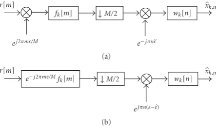
3.6.2. CFO Compensation. If the CFO is moderate, for example, in CFO tracking scenarios, or the subchannel signal modulation is robust, then the offset compensation can be performed subchannel-wise, as sketched inFigure 3(a)with the multiplication by the complex exponential sequence that undoes the frequency shift:e−jπnε. The performance of this CFO correction on a WiMAX-like FBMC system is presented in [19], although there no other synchronization tasks are considered. The frequency shifting correction will obviously not recover the information leaked to the neighboring chan-nel nor get rid of the distortion coming from 2 subchanchan-nels away, since the frequency shift is circular when performed at subchannel level. Further, the amplitude distortion due to the subchannel filter misalignments, depicted inFigure 2, is also ignored when shifting the signal back to its original location subchannel-wise.
r[m]
ej2πmε/M
fk[m] M/2
e−jπnε
wk[n] xk,n
(a)
r[m]
e−j2πmε/Mf
k[m] M/2
ejπn(ε−ε)
wk[n] xk,n
(b)
Figure3: Subchannel receiver signal model in the presence of CFO, with CFO compensation and subchannel equalization. (a) Basic model. (b) Equivalent form.
(37). This is achieved by setting the desired target responses to
Wk,n
ejω= 1
FCFO(ejω)
, (40)
forω= −π/2, 0,π/2.
Figure 3presents the subchannel model with the effect of the first two mentioned distortion types, which are pre-dominating. It includes also the basic subchannel-wise CFO correction that undoes the CFO phase rotation according to the estimated frequency shiftε. In the equivalent model (b), the effect of inaccurate CFO estimation is represented by the residual frequency modulationejπn(ε−ε).
When the frequency shift is too large, the degradation of the signal advocates for time domain solutions for correcting and possibly also for estimating the CFO. The compensation performance degrades faster than the estima-tion performance: At sufficiently high CFO, the subcarrier-wise compensation cannot recover enough of the signal of interest that has leaked to the neighboring subchannel and eliminate the interference. This logically affects higher order modulations most. However, since several pilots are used for CFO estimation, it is possible that the CFO estimate is still acceptable at the given CFO level. In this case, CFO estimation may still be done at subcarrier level, but compensation has to take place before the analysis filter bank. It is also worth underlining that when multipath channel, FTD and CFO concur in a communication link, the low-complexity subband equalizer can compensate for the three distortions at the desired frequency locations by combining (multiplying) the target frequency responses needed for correcting each of the estimated distortions.
3.7. Synchronization Scheme with Iteration. In order to estimate and compensate the effect of CFO and FTD and the interplay between these effects shown in (14) and (25) we propose a receiver to jointly estimate and correct the channel impairments subchannel-wise. First, the pilots are recovered from the received signal and from them, the CFO is estimated and the frequency shift is reverted. Then, the synchronization block estimates the FTD and uses
the obtained information when interpolating the channel between the pilots. Finally, at the equalization stage, the channel estimates at the equalization frequency points are weighted by the frequency-dependent amplitude distortion caused by the CFO (Figure 2) and the 3-tap equalizer then equalizes the signal. It is also possible to iterate this loop, since the 3-tap equalizer is able to remove a lot of distortion from the pilots, allowing for better estimates after the iteration.
4. FBMC for WiMAX
Next we describe the parameters and adjustments required for an FBMC communication system that aims to maintain a certain degree of compatibility with WiMAX specifica-tions. We have aimed to design a system taking as much parameters from the mobile WiMAX specifications [2] and the underlying 802.16e standard [3] as possible. For our setup, we have selected the time division duplexing (TDD) specification for the 10 MHz bandwidth at sampling rate
fs=1/Ts=11.2 MHz. With a transform sizeM=1024, the subcarrier spacing isΔf = 10.94 kHz. The frame duration of 5 ms allows for transmission of 47 OFDMA symbols with the cyclic prefixes permitted in the specifications. If the whole frame was to be used for a downlink (DL) transmission, FBMC could fit 53 FBMC symbols in the same time because of the absence of the CP. In a more realistic scenario including the uplink (UL) subframe, one or two FBMC symbols would have to be sacrificed for guard times between the forward and reverse links. WiMAX provides for different data configuration modes. Here, we observe two of the possible configurations: the downlink partial usage of subcarriers (DL-PUSC) and the adaptive modulation and coding (AMC23). PUSC and AMC23 use 840 and 864 active consecutive subcarriers, respectively, and have a null subcarrier at the center of the transmission band. Compared to AMC23 in OFDMA without additional filtering, if an attenuation of 40 dB outside the 10 MHz transmission band is desired, the FBMC design with the prototype filter presented above could transmit on around 50 additional subcarriers thanks to its good spectral containment. The configurations also define the size of the transmission slots and how the pilots are located within the frame. Figure 4 shows these pilot configurations for the mentioned cases. Here, each OFDMA symbol corresponds to two consecutive subcarrier samples in the FBMC model.
Frequency
Time
(a)
Time
Pilot Data
(b)
Figure 4: Pilot distribution in WiMAX (a) DL-PUSC and (b) AMC23 configurations.
Freq.
1 2 3 4 5
QAM-symbol index
P A P A P A Inconvenientpilot placing
Convenient pilot placing OQAM-symbol subindex
1 2 1 2 1 2 1 2 1 2
P A A P P A
Time
Figure5: Alternative pilot and data allocations for FBMC with DL-PUSC-like pilot pattern. P: Pilot. A: Auxiliary Pilot.
auxiliary pilot would need to be calculated, then the next one and so on successively). It is more practical to be able to calculate the interference-nulling auxiliary pilots only from the surrounding data. This can be achieved by switching the positions of the pilot/auxiliary pilot pair every other pilot. The lower part ofFigure 5shows this convenient allocation, where the interference window extends only over data and a known pilot.
5. Simulation Setup and Results
We have tested the filter bank based multicarrier system with WiMAX-like parameters and using the synchronization and channel equalization methods that have been described above. The prototype filter is the NPR optimized design with
K = 4 described inSection 3.3. The FBMC signal is sent through a quasistatic channel, if not indicated otherwise, modeled according to the International Telecommunication Union ITU-R Vehicular-A Channel guidelines [44]. This means, that for the duration of a transmission burst, the channel remains constant in time unless a certain mobility is indicated. In this case, the fading varies with time
10−2
10−1
100 Veh-A, 64-QAM, 3000 frames
BER
0 2 4 6 8 10 12 14 16 18
Eb/N0
OFDM, DL-PUSC pilots
FBMC, DL-PUSC pilots, 3-tap equalizer OFDM, PCI
FBMC, PCI, 3-tap equalizer
Figure6: Comparison between OFDM-based WiMAX and FBMC-based WiMAX with 3-tap equalizers with respect toEb/N0. 64-QAM
transmission with perfect channel information (PCI) and pilot-based estimation in a quasistatic channel.
according to the mobile velocity. For each simulation, 3000 independent burst transmissions with independent channel realizations are performed. The estimation of the synchro-nization parameters and the channel state relies on scattered pilots obtained with the auxiliary pilot technique. The combined pilot/auxiliary pilot symbol is boosted on average by 4.5 dB with respect to the data. The overall channel response is obtained from the scattered channel estimates by triangulation-based linear interpolation between the pilots. It is important to note that all the processing is done subcarrier-wise, after the AFB.
10−2
10−1
100 Veh-A,Eb/N0=20 dB, 64-QAM, DL-PUSC, fixed FTD
BER
0 0.02 0.04 0.06 0.08 0.1 CFO (1/subcarrier spacing)
Solid: FTD=0 Dashed: FTD=0.1(T/2)
PCI
(with CFO amplitude correction)
(a) BER versus CFO with fixed FTDτFTD=0 and 0.1(T/2)
10−2
10−1
100 Veh-A,Eb/N0=20 dB, 64-QAM, DL-PUSC, fixed CFO
BER
0 0.05 0.1 0.15 0.2 PCI
(with CFO amplitude correction) 0.25 0.3 FTD (1/OQAM subsymbol (T/2))
Solid: CFO=0 Dashed: CFO=0.04Δf
No marker: basic correction
CFO amplitude correction Additional synchronization iteration
(b) BER versus FTD with fixed CFOε=0 and 0.04Δf
Figure7: BER performance for different synchronization options
and equalization of a DL-PUSC zone consisting of 4 MC symbols within Vehicular-A channel atEb/N0 =20 dB, 64-QAM
modula-tion.
In an actual communication system there are synchro-nization mismatches, and a receiver has to be able to cope with the joint effect of CFO and FTD. The approach detailed above in Section 4, including the iteration of the synchro-nization/equalization stage, is applied. In our simulations we have concluded that the described synchronization and equalization chain plus one iteration delivers nearly all the improvement, since the differences in offset estimates with additional iterations are marginal.
The first results inFigure 7show the BER-performance of the mentioned system with 64-QAM atEb/N0 =20 dB in a quasistatic Vehicular-A channel. All the subcarriers are used,
10−2
10−1
100
Veh-A,Eb/N0=20 dB, 64-QAM, UL-AMC23 slots
0.15 0.1
0.05 PCI,
CFO amplitude com
pensation
0 0 0.02
0.04 0.06
0.08 0.1
BER
FTD (1/O
QAM subsy
mbol
(T/2)) CFO(1/subcarrier spacing (Δf))
4×2 slots
4×2 slots, CFO amplitude compensation, 1 iteration 16×8 slots
16×8 slots, CFO amplitude compensation, 1 iteration
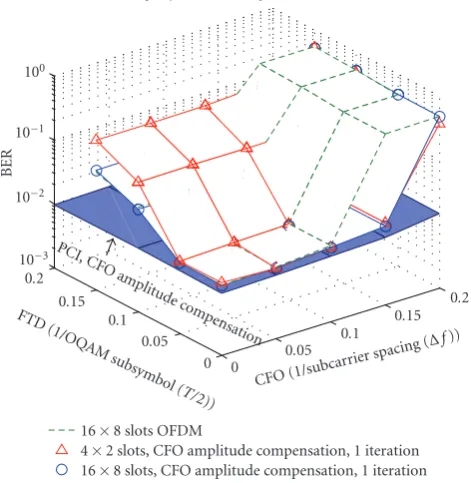
Figure 8: BER performance versus CFO and FTD for uplink transmission of 16×8 and 4×2 AMC23 slots in Vehicular-A channel atEb/N0=20 dB using 64-QAM. Different synchronization
options.
and the pilots are in the DL-PUSC configuration, simulating a downlink scenario. The transmitted burst consists of 4 FBMC symbols. Until otherwise mentioned, the FTD is calculated through averaging the phase differences between pilots. Figure 7(a) presents the BER results with changing CFO for two fixed FTD values, while Figure 7(b)presents the BER as a function of the FTD for two fixed CFO values. These figures show a clear improvement in performance with respect to CFO due to the CFO amplitude compensation. Further, the iteration of the synchronization and equalization stages also improves the BER, especially with respect toτFTD. Because improvements in 4-QAM are not that visible (since the modulation is very robust by itself), these results are not shown here. Nevertheless, a slight improvement can still be achieved.
10−3
10−2
10−1
100
Veh-A,Eb/N0=14 dB, 4-QAM, UL-AMC23 slots
0.2 0.15
0.1 0.05
0 0 0.05 0.1
0.15 0.2
BER
FTD (1/O
QAM subsy
mbol (T/
2))
CFO(1/subcar
rier spacing (Δf))
16×8 slots OFDM
4×2 slots, CFO amplitude compensation, 1 iteration 16×8 slots, CFO amplitude compensation, 1 iteration PCI,
CFO amplitude
compensation
Figure 9: BER performance versus CFO and FTD for uplink transmission of 16×8 and 4×2 AMC23 slots in Vehicular-A channel atEb/N0=14 dB using 4-QAM. OFDM- and FBMC-based
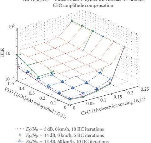
WiMAX. FBMC Synchronization performed with CFO amplitude compensation in the 3-tap equalizer and one synchronization iteration.
Figures8 and9 present the BER performances for 64-QAM and 4-64-QAM, respectively. The degradation that occurs when using a smaller burst size can be observed. This is due to the lower number of pilots available to perform synchronization and estimation. We further see that the range in which the synchronization is successful is much smaller than in the downlink case, but this is mainly due to the larger pilot separation. The effect of this is that the phase ambiguity when estimating FTD or CFO appears for
τFTDbetween 0.05 to 0.1(T/2) andεbetween 0.15 to 0.2Δf (at around ε = 0.17, because only every 6th symbol is a pilot in time direction). Figure 9 also compares the BER performance of an OFDM-based WiMAX system using the same synchronization and estimation methods as its FBMC counterpart. It occupies 16×8 AMC23 slots and the BER results are similar to the FBMC case. The main difference is that in the CFO axis the performance degradation commences earlier. Due to the CP extension of the OFDM symbols, effectively slightly “separating” the pilots in time, the phase ambiguity appears approximately whenε =0.14. Further, Figure 10 shows the effects on the FBMC system of user mobility and low SNR on the smaller burst with robust subchannel modulation. The performance is barely affected at this speed and only when the CFO approaches the nonambiguity limit the difference becomes visible. On the other hand, the stronger noise is evidently worsening the BER, but still allowing for a certain synchronization range. The following simulation results prove this by taking a closer
10−2
10−1
100
Veh-A,Eb/N0=5 and 14 dB, 4-QAM, UL-AMC23 4×2 slots,
CFO amplitude compensation + 1iteration
0.15 0.1
0.05
0 0 0.05
0.1 0.15 0.2
BER
FTD (1/O
QAM subsy
mbol
(T/2)) CFO(1/subcar
rier spacing (Δf))
Eb/N0=5 dB, 0 km/h Eb/N0=14 dB, 60 km/h Eb/N0=14 dB, 0 km/h
Figure 10: BER performance versus CFO and FTD for uplink transmission of 4×2 AMC23 slots in Vehicular-A channel at
Eb/N0 =5 dB andEb/N0 = 14 dB using 4-QAM. Static user and
user with 60 km/h mobility. Synchronization with CFO amplitude distortion correction and one iteration.
look at the estimation performance of the synchronization parameters.
The CFO estimator performance is evaluated with help of the root mean square (RMS) error with respect to the actual CFO. The RMS error of the previously presented simulation scenarios is shown for a fixedτFTD = 0.1(T/2) inFigure 11(a). The CFO estimation performance proves to be quite independent from the actual FTD, having only a minor degradation with increasing τFTD, as the interested reader can verify in [45]. In the low SNR scenario, even with the small burst and with FTD present, the estimate for the frequency offset is acceptable if the CFO stays below 7% of the subcarrier spacing. Also the user with vehicular mobility can be synchronized well by the base station. The other considered cases have a low variation of the performance with increasing CFO, until the ambiguity limit is reached. Although not presented here, the RMS CFO error of ε increases slightly if the synchronization procedure is iterated. Nevertheless, the estimates are still good enough for accurate synchronization within the WiMAX requirements for maximum CFO offset, specifically,±2% of the subcarrier spacing [3].