University of South Carolina
Scholar Commons
Theses and Dissertations
1-1-2013
Structural Origin of Mechanical Prowess In Conch
Shells
Haoze Li
University of South Carolina - Columbia
Follow this and additional works at:https://scholarcommons.sc.edu/etd Part of theMechanical Engineering Commons
This Open Access Dissertation is brought to you by Scholar Commons. It has been accepted for inclusion in Theses and Dissertations by an authorized administrator of Scholar Commons. For more information, please [email protected].
Recommended Citation
Li, H.(2013).Structural Origin of Mechanical Prowess In Conch Shells.(Doctoral dissertation). Retrieved from
STRUCTURAL
ORIGIN
OF
MECHANICAL
PROWESS
IN
CONCH
SHELLS
by
Haoze Li
Bachelor of Materials Science and Engineering Harbin Engineering University, 2007
Master of Materials Science Harbin Institute of Technology, 2009
Submitted in Partial Fulfillment of the Requirements
For the Degree of Doctor of Philosophy in
Mechanical Engineering
College of Engineering and Computing
University of South Carolina
2013
Accepted by:
Xiaodong (Chris) Li, Major Professor
Chen Li, Committee Member
Djamel Kaoumi, Committee Member
Goutam Koley, Committee Member
D
EDICATIONA
CKNOWLEDGEMENTSI owe my deep gratitude to all the people who have helped me for my doctoral study
at University of South Carolina. First, I would like to thank my advisor, Professor
Xiaodong (Chris) Li, for his insightful guidance, generous support, encouragement
through every step of my research, as well as the career promotion afterwards. His
passion for research has been an inspiration to my career. I would also like to thank
Professor Chen Li, Professor Djamel Kaoumi and Professor Goutam Koley for serving as
my committee members of dissertation review and defense. Their insightful suggestions
greatly improve the quality of this dissertation.
I sincerely appreciate the financial support of China Scholarship Council during
my degree pursuing. As well, I thank the kind help of Professor Morehouse and Professor
Kidane for my teaching assistance job.
All the group members and colleagues are truly grateful; they are like family to
me. I will always cherish the quality time spent with Dr. Zhihui Xu, Professor Gangsheng
Zhang, Professor Dalai Jin, Dr. Lihong Bao, Dr. Jianfeng Zang, Dr. Yong Sun, Dr.
Zaiwang Huang, Dr. Yanming He, and doctor-to-be Rui Li, Peng Huang, Yingchao Yang,
Jianchao Chen, Yang Sun, Ningning Song, Zan Gao, and thank their help in both my
research and daily life. The administrative staffs and technicians in the Department of
Finally, I express deepest gratitude to my parents, my father Zhongchen Li, my
mother Wenmin Zang, for their love, wise guidance and unwavering belief in me.
A
BSTRACTConch shells are natural nanocomposites with an exquisite multiscale hierarchical
architecture which exhibit coupled ultrahigh mechanical strength and toughness. What
materials design strategy renders conch shells such mechanical prowess? In this study,
micro/nanoscale structural and mechanical characterization of conch shells (Busycon carica) has been carried out. We demonstrate, for the first time, direct evidence that the previously claimed single-crystal third-order lamellae - the basic building blocks in conch
shells are essentially assembled with aragonite nanoparticles of the size ranging from 20
to 45 nm. The third-order lamellae exhibit not only elasticity but also plasticity with the
strain up to 0.7% upon mechanical loading, due to the unique nanoparticle-biopolymer
architecture in which the biopolymer mediates the rotation of aragonite nanoparticles in
response to external loading. Our finding - metal like deformation behavior overturns the
previous assumption that aragonite lamellae are brittle in nature. The three-order
crossed-lamellar architecture interlocks cracks via crack deflection along the biopolymer
interfaces in a three-dimensional manner. The interlocking mechanism and the plasticity
of third-order lamellae jointly contribute to the remarkable mechanical prowess.
We report that conch shells display an unusual resilience against high strain rate
predatory-attack vis-à-vis under quasi-static loading. Upon dynamic loading, conch shells
trigger a new defense mechanism - intra-lamella fracture, involving nanoparticle rotation
and formation of trapped dislocations, which differs from the inter-lamella fracture
Another fascinating design principle with the curve-shaped third-order lamellae is
uncovered in conch spines. Such architecture enhances the fracture strength up to 30 %
compared with that of conch shell bodies with straight reinforcements, unveiling the roles
of spines in protection from predators.
Moreover, the effects of electron beam irradiation and heat treatment on the
structural and mechanical stability of conch shells were investigated. Both conditions can
induce phase transformation from aragonite to calcite, to lime, altering the
T
ABLE OFC
ONTENTSDEDICATION ... iii
ACKNOWLEDGEMENTS ... iv
ABSTRACT ... vi
LIST OF TABLES ... x
LIST OF FIGURES ... xi
LIST OF SYMBOLS ... xiv
LIST OF ABBREVIATIONS ... xvii
CHAPTER 1INTRODUCTION ... 1
1.1ASSEMBLY STRATEGIES IN CROSSED-LAMELLAR STRUCTURE ... 4
1.2STRENGTHENING MECHANISMS OF HIERARCHICAL STRUCTURE ... 7
1.3TOUGHENING MECHANISMS OF HIERARCHICAL STRUCTURE ... 10
CHAPTER 2ASSEMBLY STRATEGY AND MECHANICAL PROWESS OF CONCH SHELLS ... 15
2.1EXPERIMENTAL ... 16
2.2RESULTS AND DISCUSSION ... 18
2.3SUMMARY ... 29
CHAPTER 3METAL-LIKE DEFORMATION IN CONCH SHELLS ... 30
3.1EXPERIMENTAL ... 31
3.2RESULTS AND DISCUSSION ... 33
3.3SUMMARY ... 44
4.1EXPERIMENTAL ... 47
4.2RESULTS AND DISCUSSION ... 48
4.3SUMMARY ... 62
CHAPTER 5MECHANICS GUIDED GEOMETRY IN CONCH SPINES ... 63
5.1EXPERIMENTAL ... 64
5.2RESULTS AND DISCUSSION ... 65
5.3SUMMARY ... 75
CHAPTER 6THERMAL INVESTIGATIONS ON STRUCTURAL AND MECHANICAL EVOLUTION OF CONCH SHELLS ... 76
6.1EXPERIMENTAL ... 77
6.2RESULTS AND DISCUSSION ... 78
6.3SUMMARY ... 87
CHAPTER 7SUMMARY AND FUTURE SUGGESTIONS ... 88
7.1SUMMARY OF MAIN RESULTS ... 88
7.2SUGGESTIONS FOR FUTURE RESERACH ... 89
L
IST OFT
ABLESTable 2.1 Young’s moduli and hardness values from different microlayers of the
L
IST OFF
IGURESFigure 1.1 Conch shell (Busycon Carica) profiles ... 3
Figure 1.2 Crossed-lamellar structure of conch shell ... 4
Figure 1.3 Growth theories of conch shells ... 5
Figure 1.4 Conch shells strengthening origins ... 8
Figure 1.5 Conch shells toughening strategies ... 11
Figure 2.1 SEM images of fractured shell surface and schematic of crossed-lamellar architecture ... 20
Figure 2.2 Optical and AFM images of the microindentation fractured conch surface ... 21
Figure 2.3 Nanoindentation characterization ... 23
Figure 2.4 Nanostructure details of the conch shell ... 25
Figure 2.5 Structural characterization of the third-order lamellae ... 26
Figure 2.6 Polycrystalline diffraction characteristic of a third-order lamella ... 28
Figure 3.1 Inelastic deformation of conch shells ... 33
Figure 3.2 AFM three-point bending on a single third-order lamella ... 35
Figure 3.3 In situ TEM observation of a third-order lamella upon bending ... 37
Figure 3.4 Phase transformation under in situ irradiation ... 38
Figure 3.5 EELS analyses on the influence of irradiation ... 39
Figure 3.6 Sketches of lattice evolution during phase transformation ... 43
Figure 4.1 Compressive true stress-strain curves in quasi-static and dynamic loading conditions ... 48
shell) and geological aragonite ... 50
Figure 4.3 Fractured morphology of a specimen after quasi-static compression ... 52
Figure 4.4 Comparison in completeness of third-order lamellae after dynamic and quasi-static loading rates. ... 54
Figure 4.5 Fracture model of a third-order lamella under dynamic loading and mechanical characterization of one fractured part ... 55
Figure 4.6 Sketches of lamellar fracture modes ... 57
Figure 4.7 Disordered orientations of nanoparticles inside a dynamically compressed third-order lamella ... 59
Figure 4.8 Analysis of an edge dislocation in the dynamically deformed third-order lamella ... 60
Figure 5.1 Sketches of the hierarchical structure in a spine ... 65
Figure 5.2 SEM images of fractured spine surface ... 66
Figure 5.3 Compressive stress-stain curves for the middle layer of spines and conch bodies ... 69
Figure 5.4 Fracture mechanisms of conch spine and body ... 70
Figure 5.5 Models of curving and straight second-order lamellae and their stress equilibrium analysis ... 72
Figure 5.6 Friction coefficient of conch shells ... 75
Figure 6.1 TGA and DTA curves of the conch specimen upon heat treatment to 1000 °C in air... 78
Figure 6.2 XRD patterns of conch samples heat treated with diverse temperatures ... 79
Figure 6.3 SEM images of pristine and heat treated conch shells ... 80
Figure 6.4 TEM analysis of heat treated samples ... 82
Figure 6.5 Nanoindentation impressions and corresponding load-displacement curves of shells ... 83
Figure 6.7 Biopolymer identification ... 85
Figure 6.8 Mechanical characterization of biopolymer ... 85
L
IST OFS
YMBOLSh* Critical length scale
a Proportionality constant
γ Surface energy
E Elastic modulus
σth Theoretical stress
σcr Critical buckling stress
ΦM Mineral content
υ Poisson ratio
EP Elastic modulus of biopolymer
Ktot Stress intensity factor
KP Stress intensity factor of primary load
KS Stress intensity factor of residual stress
ε Bending strain
r Half thickness of lamella
R Radius of bending curvature
I Moment of inertia
b Width of lamella
h Height of lamella
F Applied load
kn Spring constant of lamella
ki Slope of Force - Piezo Z position curve
T Temperature increment
l0 Thickness
k0 Thermal conductivity
R0 Radius of hole in supporting film
r0 Radius of irradiated region
W Total absorbed power
ε0 Proportional absorbed energy
V Acceleration voltage
ρ0 Current intensity
Emax Maximum transferred energy
E0 Kinetic energy
A Atomic mass
m Strain rate sensitivity
σ Applied stress
ε Applied strain
N Total amount of fractured third-order lamellae
Q Energy consumption under compression
q Energy consumption under bending
GInter Energy release rate of inter-lamella crack tip
GIntra Energy release rates of intra-lamella crack tip
ΓP Fracture toughness of biopolymer
α Dundurs’ parameter
EL Elastic modulus of third-order lamella
v* Activation volume
kc Boltzmann constant
T0 Absolute temperature
b Burgers vector
σs Applied stress on the cross section
τ0 Constant friction stress
τC Coulomb friction stress
σP Radial compressive stress
L
IST OFA
BBREVIATIONSACC ... Amorphous Calcium Carbonate
SEM ... Scanning Electron Microscope
TEM ... Transmission Electron Microscope
HRTEM ... High-Resolution Transmission Electron Microscope
AFM ...Atomic Force Microscope
FESEM ... Field Emission Scanning Electron Microscope
FFT ... Fast Fourier Transformation
EBID ... Electron Beam Induced Deposition
EELS ... Electron Energy Loss Spectroscopy
SAED ... Selected Area Electron Diffraction
SRS ... Strain Rate Sensitivity
TGA ... Thermogravimetric Analysis
DTA ... Differential Thermal Analysis
XRD ... X-Ray Diffraction
RT ... Room Temperature
CHAPTER
1
I
NTRODUCTIONThe past decades are filled with humans’ efforts in developing structural materials with
combination of remarkable mechanical reliability (including strength, toughness) and low
weight for survival and social needs. Unfortunately, it is challenging to achieve
simultaneously high strength and toughness in engineered materials because of the
trade-off relation between the two properties.1 For the metallic materials, the
well-performed ductility and fracture toughness are at the expense of low level yield
stress. Several strengthening methods have been identified, such as micro-/nano-
particulate and/or fiber reinforcements incorporation, grain size refinement
(nanomaterials), dislocation introduction (for example, stacking faults).2 However, these
modifications inevitably result in elevated brittleness. On the other hand, the inherently
stiff ceramic materials are short of applicable ductility as well as toughness. Although the
ductile second phase, phase transformation and predesigned crack arrangement, to some
extent, soften the materials with higher fracture toughness,3 the limited amelioration
together with reduced strength cannot fulfill the specific requirements. Consequently, a
challenging issue is surfaced: How people can overcome such conflicting issue and
Knowing the best in materials-by-design for functionality, Mother Nature,
however, has already elegantly solved this problem. Living organisms have evolved over
millions of years to a level of optimization not currently achieved in engineered system.4
Among these, seashells, which are acknowledged the best natural body armors for
protecting their soft bodies from predator attacks, possess salient mechanical strength and
eminent toughness - several times increase in stength and some thousand fold
enhancement in toughness with reference to their major components.5-8 Two major
constituents, regardless seashell species, aragonite (a mineral form of CaCO3) and
organic biopolymer, are known to be arranged hierarchically into multiscale architecture
via bottom-up self-assembly. To be specific, via converting soluble ions in water into
minerals,9 characterized as biominerlization, living organisms combine brittle ceramics
and macromolecules together to form such biomaterials.10 Within the countless seashells
found underwater, they are approximately contained in five phyla, i.e., mollusca,
arthropoda, echinodermata, brachiopoda and annelida. Nowadays, bivalvia and
gastropoda in mollusca are frequently investigated because of their exquisite structures
and availability.9 In addition, the identifying structural morphologies are classified as
prismatic, nacreous, crossed-lamellar, foliated and homogeneous.11,12 Crossed-lamellar
structure, with its complex multiscale arrangement in frequently varied orientation, is
widely spotted in seashells. Their achieved unparallel mechanical and physical properties
To deepen the understanding of relationship between structure and property in
seashells, we select conch shell (Busycon carica) as an example. As shown in Figure 1.1, the conch profiles as the high spire and a siphonal canal with several spines evenly
separated at the end of swirl. Microscopically, the bulk shell consists of three microlayers
(outer, middle and inner) based on their diverse orientations of first-order lamellae
(Figure 1.2a). Each microlayer is comprised by horizontally overlapping numerous
plate-like first-order lamellae. A first-order lamella is formed by numerous second-order
lamellae, and a second-order lamella consists of a bundle of third-order lamellae which
have nanoscale cross section and micro-level length (Figure 1.2b). Within a microlayer,
the orientation of third-order lamellae is changed in neighboring first-order lamellae by
900. In the bulk shell, the orientation of first-order lamellae in the outer, middle and inner
layers is varied as 00/900/00.
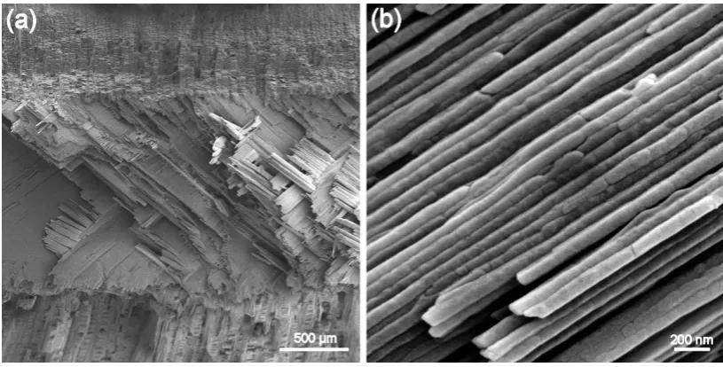
Figure 1.2. Crossed-lamellar structure of conch shell. (a) Overview of fracture surface. (b) A close-up view in showing nanoscale third-order lamellae.
1.1 ASSEMBLY STRATEGIES IN CROSSED-LAMELLAR STRUCTURE
How do the conch shells manage to achieve such compact multiscale hierarchical
structure? We mainly list several growth mechanisms during biomineralization. Growth
twins (Figure 1.3a) were reported in third-order lamellae within crossed-lamellar
structure.13-16 This formation with the (110) mirror plane is ascribed to aragonite
crystallographic privilege, i.e. orthorhombic symmetry leads to pseudohexagonal
arrangement.17 Kitamura et al.18 anticipated the faster growth effect of twins in crystal.
The alignment of twin boundaries is in good agreement with lamellar length direction,
indicating the growth path of third-order lamellae. In addition, growth twins were also
found in other ceramics, for instance, calcite and vaterite.16,18 Suzuki and Pokroy et al.
observed a thin layer with crystalline particles deposited on the growing surface,
theories, including amorphous calcium carbonate (ACC) precursors and polymer-induced
liquid precursors,21-27 were proposed, respectively, to clarify the possible pathways of
mineralization under ambient aqueous conditions. With the aid of precursors’ mobility, it
facilitates the complex construction with dissimilar orientations.
Figure 1.3. Growth theories of conch shells. (a) Growth twins inside a third-order lamella with boundaries aligned parallel to lamellar length orientation. (b) Spiral formation.39 (c) New-born third-order lamellae in a bio-envelop.
Consisting of proteins with no more than 5% in mass, biopolymer (polymer,
molecules and surfactants) exerts a tremendous influence on guiding and assisting crystal
growth into the hierarchical structure, with the postulated functions as stabilizers, soft
templates and additives.19,22,28 Weiner et al. brought forth an organic-nucleation theory29
to discuss that the protein-based matrix was inclined to bind ions at certain spots to create
an appropriate plane, followed by the crystal nucleation as the local concentration is
increased. Such pre-designed method creates well-ordered and desired structures. Tissue
regeneration studies provided important information concerning the organic role.30-38
growing surface.39,40 It was proposed that the formation was affected by the higher
concentration of organic matrices located along the growth frontline than the interspersed
distribution of bio-protein within 'normal' lamellar pattern. Enveloped crystalline growth
inside biopolymer shields was first reported by Nakahara et al.41 A thin organic substance
is first deposited on the inner surface of shell; accompanied by the mineralization,
granular crystals are formed within various bio-envelopes in such organic matrix as
shown in Figure 1.3c. When the thickness of layer is increased, the grown-up crystals
result in the contact between adjacent envelopes and finally enclose growth lines.
Oriented attachment method was first found in a hydrothermal process assembly by TiO2
particles;42 it has turned to a hot topic concerning biomineralization because its products’
shape and nanoparticles-constructed single-crystal character are similar to biominerals.
Through locking in high energy surfaces of two approaching particles, the
crystallographic fusion eliminates energy to makes possible the further growth.43,44
Thermodynamically, oriented attachment guarantees the defect free inside together with
achievable intricate structure.
Most of the mechanisms listed challenge the classical crystal growth theory,
known as 'Ostwald ripening process',45 during which the crystalline nuclei first precipitate
from the supersaturated liquid. After reaching as the size of 'critical crystal nuclei', the
free enthalpy of the system becomes negative and therefore propels further growth at the
cost of smaller ones. To date, all the studied growth models refer the individual
single-crystal-characteristic electron diffraction pattern.46-49 However, considering the
listed biomineralization methods, the possibility of particles assembly strategy cannot be
simply eliminated. In our work, we demonstrate direct evidence that the previously
claimed single-crystal third-order lamellae in conch shells are essentially assembled with
aragonite nanoparticles of the size ranging from 20 to 45 nm. To support the conclusion,
we also resorted to mechanical deformation and heat treatment to reveal the nanoparticle
formation. The new-finding assembly units will deepen our understanding in
biomineralization.
1.2 STRENGTHENING MECHANISMS OF HIERARCHICAL STRUCTURE
The conch shells’ remarkable effectiveness in combining superior strength and
toughness with reference to brittle ceramics and weak organic materials attracts interests
in the field of biomimicry. The following mechanisms are ascribed to the origins in
strengthening bioceramics.
The wave-like third-order lamellae were found by Yang et al.;50 such micro-scale
interlocking by the advantage of curvature induces transverse dilation and interfacial
hardening upon sliding, enhancing materials’ strength as well as toughness. Likewise, the
surface roughness of third-order lamellae owns the similar function but performs down to
nanoscale. Caused by the mutual movement restriction with the help of nanoasperities,
the elevated force for further slip alleviates stress concentration and initiates other
reported the strengthening mechanism of mineral bridges (Figures 1.4c and d) through
considering the bridge number and distribution status.6
Figure 1.4. Conch shells strengthening origins. (a) and (b) Nanoasperities of third-order lamellae and corresponding deformation mechanism. (c) and (d) Mineral bridges and detailed fracture behavior, respectively. (e) and (f) Organic materials and deformation detail.28,54
The revealed nanoparticles in our studies exert the influence in strengthening as
well. It is accepted that a defect-free material can reach its theoretical strength; however,
the protein molecules between the ceramic particles are equivalent to crack flaws because
of their comparably low stiffness. Gao et al.53 investigated how biological materials
achieved high strength with the preexist cracks. From the standpoint of fracture
2
th
E a h
σ γ
≈
∗
1.1
where a is a proportionality constant, γ is the surface energy, E and σth represent the
elastic modulus and theoretical stress, respectively. It indicates that the fracture strength
is sensitive to structural size, namely, stress concentration caused by flaws leads to failure
above certain crack length. Yet the size drops down around tens of nanometers, the
materials become insensitive to defects and maintain high strength.
Biopolymer is not only an irreplaceable factor during the biomineralization but
also proved to possess critical roles in the point of mechanical performance despite its
low content (Figures 1.4e and f). Zhao et al.55,56 reported the declined magnitudes in both
strength and ductility after heat treatment, which directly points out the importance of
biopolymer. Xu et al.57 found the strengthening phenomenon of biopolymer and proposed
a coiled-spring model, both of them in turn explains the reason of weakened properties
upon burning out biopolymer. Moreover, Ji et al.58 proposed a one-dimensional model to
illustrate the protein’s task in transferring the load between lamellae via shear. Ji et al.59
also proposed a multi-buckling model, differing from classical Euler buckling that stress
degradation is caused by increased aspect ratio. They indicated that the buckling stress
was independent of aspect ratio as long as the aspect ratio value reached high enough,
especially for conch third-order lamellae with nanoscale cross section and microscale
length. Equation 1.2 below provides a threshold stress value, below which the lamellae
) 1 )( 1 ( 3 2 2 3 M M P M cr E E Φ − − Φ = υ
σ 1.2
Here, σcr indicates the critical buckling stress, ΦM is the mineral content, υ is Poisson
ratio, EM and EP are elastic moduli of mineral and biopolymer, respectively.
1.3 TOUGHENING MECHANISMS OF HIERARCHICAL STRUCTURE
Comparing with the strengthening mechanisms aforementioned, researchers own
a more pressing need to investigate the achieved ultrahigh fracture toughness by
assembling plain-performance constituents in conch shells. Crack deflection and
bifurcation (Figure 1.5a) are widely observed and studied fracture behaviors in
hierarchical structure.4,47,49,54 The large discrepancy in stiffness between biopolymer and
ceramic renders cracks find an easy way for propagation. Such delocalization of damage
as well as crack branching decreases stress concentration and significantly impedes
fracture process by confining in a small region. Kamat et al.60 reported the large-scale
crack bridging in crossed-lamellar structure and evaluated its contribution to the fracture
toughness (Figure 1.5b). Bridged by intact elements in middle layer, the formation of
delaminated cracks along the lamellar interface between outer and inner microlayers
complicates the deformation behaviors in combination with Mode I loading (bending)
and Mode II loading (tension). Therefore, such behavior is expected to be a softening
factor (decreasing crack opening displacements) and consumes extra energy after
mechanical failure. Kessler et al.61 found the multi-cracking response after bending tests
interaction bring about mutual shields and lower the stress intensity factor at the crack tip
in comparison to single-crack condition. Such deformation behavior avoids catastrophic
fracture and improves structural reliability.
Figure 1.5. Conch shells toughening strategies. (a) Crack propagation in deflected and branched manners.49 (b) Bridging a delamination between two microlayers.60 (c) Multi-cracking along the lamellar interlayer.48
Lamellar sliding,56 some other studies treat it as pull-out, is found in the deformed
structure. It is proposed to enhance materials’ performance by consuming energy under
frictional sliding.49 Besides breaking bonds of macromolecules, the sliding takes
advantage of lamellae features (for example, curving lamellae, nanoasperities and mineral
bridges in Figure 1.4) to increase fracture strain and materials’ flaw tolerance. Cook et
al.62 studied the effect of adhesive soft bio-interface and proposed the corresponding
models on the toughening mechanism. Zhao et al.55,56 reported the absence of biopolymer
not only resulted in the decreased strength but also fracture toughness. As a matter of fact,
most of mentioned toughening mechanisms cannot leave the assistance of biopolymer,
evidence of lessened strength and toughness upon dry condition. It is believed that the
constraint macromolecules activity in transition from wet to dry condition might affect
the outcome. Its viscoelastic-plastic characterization enriches the engineered synthesize
field.
After listing several small-scale (including nano- and micro-scale) toughening
factors, we turn our attention to the macro-size design principle - hierarchical
arrangements, the original found and studied aspect. The mechanical properties of
crossed-lamellar structure are mostly depended on all levels of organization’s interaction.
Through the frequently changed lamellar orientation, the increased crack path inhibits the
thrust from propagating directly down through the entire bulk materials. Eichihorn et al.66
reported the residual stress upon deformation inside a hierarchical structure through
energy variable X-ray diffraction. Generally, such compressive residual stress functions
in closing-up the existing flaws in the materials, and improve the toughness in fracture. It
is known that the existence of a residual stress requires cracks to achieve increased
energy to break through because an additional stress intensity factor66Ktot is introduced.
S P tot K K
K = + 1.3
In this equation, KP and KS represent the stress intensity factor of the primary load and corresponding formation of residual stress, respectively. The interface between different
microlayers is assumed to carry out higher value of residual stress than the rest in bulk
materials, since the lamellae orientation is drastically changed and/or this stress might
accordingly acquired for further growth and propagation through the region with residual
stress.
Until now, all the studied deformation mechanisms mainly focus on the
interaction between stiff ceramic-lamellae and soft biopolymer, little attention is paid to
the mechanical contribution of individual third-order lamellae. In this work, we display
direct evidence that the ceramic based third-order lamellae exhibit not only elasticity but
also plasticity upon mechanical loading. Our findings in metal like deformation behavior,
for the first time, prove the role of lamellae as both deflecting cracks into interlayer and
performing plasticity to shield cracks from breaking through directly, and overturn the
previous assumption that aragonite lamellae are brittle in nature. The plasticity provides a
new solution to account for the ultrahigh robustness of conch shells.
The reported mechanical performance is based on the traditional mechanical tests
under quasi-static loading rates, such as bending,4,46,48,56,60,61 compression,49,50,67
indentation,55,68,69 shear. Few efforts shed light on the encountered aggression of body
armors in daily life - dynamic penetration impacts. In the study, we unveil that conch
shells display an unusual resilience against predatory attacks by a series of uniaxial
compression under diverse loading rates. In high-strain-rate compression (strain rate ~
103 /s) shells highlight significantly high fracture strength vis-à-vis under quasi-static
loading (strain rate ≤ 10-2
/s). The natural body armors ingeniously activate a new defense
mechanism - intra-lamella fracture against high-speed attacks, which differs from the
self-strengthening mechanism is inherently associated with the small localized activation
volume for deformation.
Conch shell bodies have been repeatedly placed as the priority for investigation in
structure and mechanics. As the primary tool against predatory attacks, no effort has been
undertaken on the conch spines. Accordingly, we report one prominent design principle
in spines with curve-shaped third-order lamellae. Such biocomposites’ assembly strategy
significantly enhances the fracture strength up to 30 % compared with that of conch
bodies in straight reinforcements, proving the roles of spines in protection. The
mechanical improvement is ascribed to the curvature effect in breaking reinforcements in
lieu of sliding effect in conch bodies.
The original design of shells by Mother Nature is for the application under
environmental temperature. Yet, considering the structural and mechanical stability upon
high temperature, the heat treatments at 310 °C, 500 °C and 900 °C were performed. It is
reported that low-content biopolymer, which can be easily burned out in the studied
heating conditions (310 °C), exerts a significant role in maintaining high mechanical
performance. The phase transformation (aragonite - calcite at 500 °C, calcite - lime at
CHAPTER 2
A
SSEMBLYS
TRATEGY ANDM
ECHANICALP
ROWESS INC
ONCHS
HELLSConch shells are renown for their unique three-order crossed-lamellar aragonite structure
(99 vol.%) integrated with biopolymer (1 vol.%),47,48,60,68 providing three dimensional
crack deflection pathways upon mechanical loading.46,49,56,61 To date, the mechanical
prowess has not been completely clarified. Their structrual details and how they
coordinate and jointly contribute to the mechanical robustness are still, to a large extent,
unknown.70-72 It has been long thought that the basic building blocks in conch shells are
the third-order lamellae which are single crystal aragonite and brittle.46-49 Recent studies
on nacre, which consists of stacked aragonite platelets sandwiched with organic
biopolymer, have revealed that the previously assumed basic building blocks - aragonite
platelets - are actually composed of a large number of nanoparticles with an average
particle size of 15-180 nm.7,73,74 Several key questions are raised, but not answered: Are
aragonite nanoparticles also the basic building blocks for conch shells in view of similar
biomineralization among seashells? If so, how are the aragonite nanoparticles assembled
into the three-order crossed-lamellar architecture? How do such multiscale hierarchical
three-order lamellae coordinate to protect the soft body from foreign (mechanical) attacks?
architecture to achieve the same mechanical prowess? To address these critical questions,
we need to probe the aragonite nanoparticles in conch shells to advance our
understanding of the coordination mechanism among the three-order lamellae with
reference to their roles in the shell’s mechanical performance. In this context, we applied
a combination of state-of-the-art methods including scanning electron microscopy (SEM),
transmission electron microscopy (TEM), atomic force microscopy (AFM), and
micro/nanoindentation to conch shells to reveal the multiscale hierarchical assembly
strategy and mechanical prowess in conch shells with the goal of reproducing conch
shell’s performance in engineered materials.
In this paper, we report, for the first time, that the previously assumed single
crystal third-order lamellae are essentially assembled with nanoparticles of the size
ranging from 20 to 45 nm. The aragonite-nanoparticle-constructed third-order lamellae
are not brittle, but ductile. The multiscale hierarchical architecture interlocks cracks via
crack deflection along the interfaces in all three-order lamellae, thus confining the
damage in a small region. The findings advance the understanding of the mystery of
conch shell’s mechanical robustness, provide additional design guidelines for developing
bioinspired nanomaterials, and lay a constitutive foundation for modeling the deformation
behavior of seashells.
2.1 EXPERIMENTAL
In this study, structural and mechanical characterization was performed on the
Melongenidae family. The shells were retrieved from the South Carolina coast along the
Atlantic Ocean. After cleaning-up, all samples were kept in the wet condition for
mechanical tests. Macroscopic bending tests were carried out with an aim to investigate
shell’s fractured surface and the resistance to deformation and fracture. In addition, the
residual segments of interest were treated in 1% KOH solution for 2 h, followed by 2 min
distilled water ultrasonication for the observation of nanoparticles inside individual
third-order lamellae. The fracture surfaces were coated with a 10 nm thick gold-film
before field emission scanning electron microscopy (FESEM) (Zeiss ultra plus thermal
field emission scanning electron microscope) observation. The samples for high
resolution transmission electron microscopy (HRTEM) observation were prepared by
slicing the shell with microtome (Microm HM 325 Rotary Paraffin Microtome, Thermo
Fisher Scientific Inc., Kalamazoo, MI) and then transferred onto the holey carbon-coated
copper film for the observation in a JEOL JEM 2100F transmission electron microscope
(JOEL Ltd., Peabody, MA) at an accelerating voltage of 200 kV.
The mechanically polished samples for indentation and AFM observation were
first cut with a water-cooled, low-speed diamond saw, then ground and polished using
abrasive papers and powders of 50 nm in size, and finally rinsed thoroughly with distilled
water prior to testing. Nanoindentation tests were executed using a Triboscope
nanomechanical testing system (Hysitron Inc.) in conjunction with the Veeco AFM
system (Veeco Dimension 3100 AFM system, Veeco Metrology Group, Santa Barbara,
indenter, a diamond Berkovich three-sided pyramid with a force resolution of about 50
nN and displacement resolution of about 0.1 nm. Microhardness tests were conducted on
the mechanically polished shell specimens using a four-sided, pyramid Vickers diamond
indenter by holding the indenter tip at the peak indentation load of 2 N for 15 s. The
polished surfaces and indentation impressions were examined by AFM.
2.2 RESULTS AND DISCUSSION
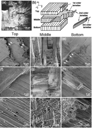
As schematically demonstrated in Figure 2.1b with reference to Figure 2.1a, the
conch shell has the ‘plywood’-like architecture constructed with three microlayers,
termed as bottom, middle, and top microlayers. The third-order lamellae, reported to be
the basic building blocks for the shell structure, have the dimension of 60-150 nm by
120-330 nm in cross section and hundreds of micrometers in length. The individual
third-order lamellae are bundled up with biopolymer to form the larger structure - the
second-order lamellae with 5-30 μm in thickness and 20-50 μm in width. Likewise, the
second-order lamellae are stacked together to form the first-order lamellae of 10-70 μm in
thickness and several micrometers in width. By horizontally overlapping the first-order
lamellae, a microlayer is hereby constructed. From one microlayer to the next, the
orientation of the first-order lamellae differs by 800~900. In addition, third-order lamellae,
oriented at 350~450 to the bulk material’s surface, are organized in about 900-difference
orientation within the adjacent first-order units. Such multiscale hierarchical
energy dissipation. The following section will elaborate the correlation between the
multiscale hierarchical assembly strategy and mechanical prowess in the conch shells.
Figure 2.1a presents an overview of the fracture surface of a conch shell. The
close-up views of the fracture surface (Figures 2.1c-k) reveal that cracks were deflected
along the lamellar interfaces, i.e., first-order (Figures 2.1c and d), second-order (Figures
2.1e and h) and third-order lamellar (Figures 2.1i and k) interfaces. These crack induced
lamellar separations indicate that cracks were simultaneously deflected in a three
dimensional manner at different hierarchical levels. Served as integrated shields with
frequently-varied lamellar orientations, the three microlayers (top, middle and bottom
layers) deflect and branch cracks between layers, preventing the plain intrusion from the
top layer directly down to the bottom layer.
To simulate the predators’ sharp-teeth attacks that a conch shell often encounters
in deep sea, a Vickers indenter was used to intrude the shell and the resulting damages are
presented in Figure 2.2. The top, middle, and bottom layers exhibit similar damage
patterns (Figures 2.2a-c). Upon indentation, the indenter generated the stress
concentrations around the corners of the indenter tip. Unlike polycrystalline metals and
ceramics in which cracks initiate at each corner of the indenter and further propagate
along the corners/diagonals, the conch shell exhibits feather-like feature with short major
cracks (as shown in Figures 2.2a-c) scattering along the indenter margins. This cracking
pattern differs from the single long major cracks at each corner of the indenter observed
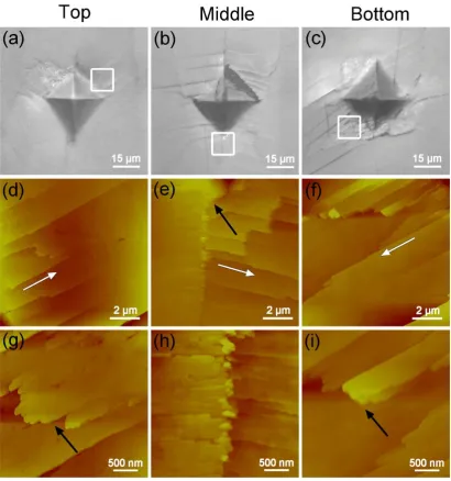
Figure 2.2. Optical and AFM images of the microindentation fractured conch surface. (a–c) Optical images of microindentation marks on the different layers of polished shell surface. (d–i) AFM images of the boxed areas in Figs. (a–c). (d–f) The white arrows show the orderly linear cracks along the second-order lamellar interfaces. (g) and (i) Cracks traverse lamellae as indicated by the black arrows.
In conch shells, the short major cracks formed primarily at the first-order lamellar
interfaces if the indenter was positioned with the stress level high enough to initiate
lamellar interfaces, the cracks were further branched along second- and third-order
boundaries, as indicated by the white arrow in Figure 2.2e. Some other major cracks
propagated along the second-order lamellar interfaces, as indicated by the white arrows in
Figures 2.2d and f. The close-up AFM images reveal that a few quite short cracks were
also formed along the corners of the indenter (see the upper part of Figure 2.2f). Indicated
by black arrows in Figures 2.2g and i, these short cracks were terminated by breaking
through lamellae. Moreover, the formation of step-like surfaces (Figures 2.2g - i) from
well-polished cross sections demonstrates the third-order lamellae were squeezed in and
out upon deformation. Clearly, the three orders of lamellae jointly contribute to the
mechanical prowess of the shell via buffering cracks in a three dimensional manner,
confining the damage to a relatively small volume. The elongated crack paths in conch
shells provide evidence for enhanced toughness.
It has been long thought that the third order lamellae are brittle single crystal
aragonites. However, only few broken lamellae were observed on the fracture surface of
the shell (Figure 2.1). This raises the question: Are the aragonite lamellae ductile? To
answer this question, nanoindentation tests were performed on individual third-order
lamellae. To eliminate the anisotropic effect studied by Bignardi et al.76, the loading
direction was arranged at the same angle (~ 45o) to the orientation of third-order lamellae
for all three microlayers. As a result, three microlayers (top, middle and bottom) have
properties indicates the assembly strategy and constituents are identically applied in all
three microlayers.
Table 2.1. Young’s moduli and hardness values from different
microlayers of the conch shell.
Young’s modulus (GPa) Hardness (GPa)
Top 89.1 ± 5.2 5.6 ± 0.3
Middle 89.0 ± 7.1 5.8 ± 0.4
Bottom 83.2 ± 7.3 5.7 ± 0.5
Mean values and standard deviations.
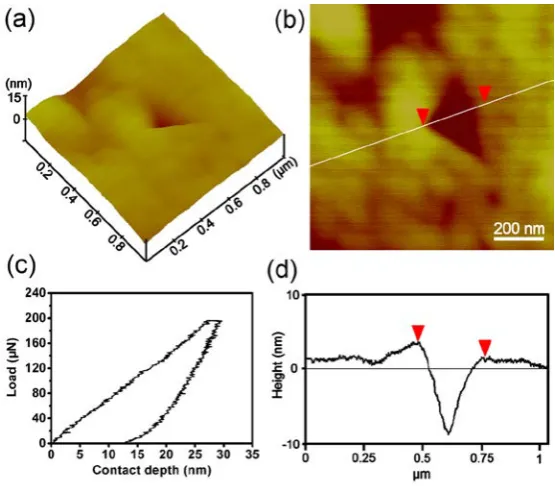
Figure 2.3 displays a representative nanoindentation load-displacement curve, the
corresponding indentation impression and cross-sectional surface height profile.
Surprisingly, no cracks were found on inspection of the area around the indent (Figures
2.3a and b), moreover, the pile-up77 was evident in the cross-sectional surface height
profile (Figure 2.3d), pointing toward ductile deformation. Such observed behavior
overturns the previously-assumed brittle characteristic for the conch shell aragonite. How
do so-called brittle aragonite lamellae exhibit ductility? Below we elucidate the structural
origin that renders ductility of the third-order lamellae.
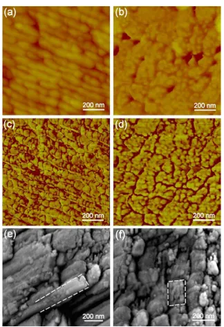
Figure 2.4 shows the AFM and SEM images of the third-order lamellae. The
AFM and SEM images jointly uncover nanoparticles with a diameter ranging from 20 to
45 nm in individual third-order lamellae. These nanoparticles are assembled to form
individual third-order lamellae. The cross-sectional view of the third-order lamellae
(Figures 2.4b, d and f) unveils that a single third-order lamella is not just a string of
nanoparticles, but composed of a few bundles of nanoparticle strings. The AFM phase
images (Figures 2.4c and d) further reveal that the nanoparticles are glued up into the
third-order lamellae by the biopolymer. Our previous study74 showed that KOH solution
could etch off the biopolymer phase in seashells, but preserved the aragonite phase.
Accordingly, the SEM images of the conch shell after 1% KOH solution treatment
Figure 2.5. Structural characterization of the third-order lamellae. (a) TEM image of a bundle of third-order lamellae. (b) Electron diffraction pattern from the boxed area of (a), displaying the single-crystal diffraction characteristic.
Previous studies have shown that the third-order lamellae diffract as single-crystal
in transmission electron microscopy.48,60,61 Likewise, we obtained the single-crystal
diffraction pattern (a series of regular spots) from a bundle of third-order lamellae in
Figure 2.5, which is apparently in contradiction to our AFM and SEM discoveries (Figure
2.4) that individual third-order lamellae are polycrystalline materials. To puzzle out the
nanoparticle assembly mechanism, HRTEM was resorted to probe the atomistic structure
of third-order lamellae.
Figure 2.6 shows the HRTEM images and respective fast Fourier transformation
(FFT) patterns of a part of third-order lamella. The electron diffraction pattern of the
single third-order lamella exhibits polycrystalline characteristics (as indicated by the
nanoparticles. This is in good agreement with the AFM and SEM observations (Figure
2.4). The FFT analysis reveals that these nanoparticles are aragonite (Figure 2.6a').
Close-up views of lattice images and corresponding FFT patterns of the four boxed areas
b, c, d and e in Figure 2.6 reveal that areas b, c, and d have different crystal orientations,
indexed as [101], [212] and [123] zones, respectively. When the three diffraction
patterns are superposed (Figures 2.6 b"+c"+d"), they form a polycrystalline diffraction
pattern (Figure 2.6a"). The finding of aragonite nanoparticles inside individual third-order
lamellae overturns the conventional single-crystal concept.
The next question is how these aragonite nanoparticles are assembled into
individual third-order lamellae? We found amorphous phase (biopolymer) in the
interstitial sites among nanoparticles, as shown in boxed area e in Figure 2.6e. This
suggests that amorphous aggregation is an assembly mechanism during biomineralization
process. The amorphous layer between nanoparticles holds the surrounding nanoparticles
together to form robust individual nanowire-like third-order lamellae. Upon mechanical
loading, the viscoelastic-plastic biopolymer between nanoparticles acts as “rubber-bands”
and thus facilitates the particle rotation,78-81 contributing to the deformability of
individual third-order lamellae. This also can explain why only few broken lamellae were
observed on the shell’s fracture surface and the pile-up was seen around the
nanoindentation impression (Figure 2.3d). The pile-up might result from the rotation of
2.3 SUMMARY
In summary, the conch shell is a highly organized composite with a unique
three-order crossed-lamellar architecture specially designed to protect the soft body from
foreign (mechanical) attacks. The basic building blocks in the conch shell are aragonite
nanoparticles that are used to construct the third order lamellae. Such
nanoparticle-constructed third-order lamellae are not brittle, but ductile. The three orders
of lamellae jointly contribute to the mechanical prowess of the shell by buffering cracks
in a three-dimensional manner, confining the damage to a relatively small volume. The
three microlayers (top, middle and bottom layers) serve as integrated shields with
different lamellar orientations with the purpose of deflecting and branching cracks
between layers, thus preventing the crack intrusion from the top layer directly down to
the bottom layer. The findings advance the understanding of the mystery of conch shell’s
ultra-high mechanical robustness, provide additional design guidelines for developing
bioinspired nanomaterials, and lay a constitutive foundation for modeling the deformation
CHAPTER 3
M
ETAL-L
IKED
EFORMATION INC
ONCHS
HELLSIt has long been assumed that the basic building blocks of conch shells are aragonite
third-order lamellae characterized as single crystal and brittle. However, we revealed the
nanoparticles-constructed third-order lamellae in the recent studies.82 Relative studies on
conch shells’ remarkable toughness persist on the three-dimensional crack propagation
along the weak biopolymer bio-interlayer because of the large discrepancy in mechanical
stiffness between aragonite and biopolymer.68 Few efforts have been undertaken towards
the mechanical roles of individual third-order lamellae. Extensive work on nacre, which
consists of stacked nanoparticles-assembled aragonite platelets sandwiched with organic
biopolymer, has shown that the toughening strategy is not simply derived from the zigzag
breakage along the biopolymer interlayer between staggered arrangements of aragonite
platelets. The revealed nanoparticles inside platelets also blunt cracks from invading
straightforward via an intergranular manner.83 Accordingly, several critical questions are
raised, yet not addressed in conch shells: What is the deformation behavior of a single
third-order lamella? In lieu of the identified toughening mechanisms in conch shells, is
contribute to the conch shells’ eminent toughness? Can we learn from this to biomimic
counterparts?
In this paper, via conducting tensile and three-point bending tests on bulk shells as
well as nanoscale three-point bending on individual third-order lamellae, we display
direct evidence for the first time that ceramic-based third-order lamellae, surprisingly,
exhibit not purely elastic but also plastic deformation like metals upon external loading.
Mediation of nanoparticles assisted by surrounded biopolymer is anticipated to the origin
of such plasticity. This metallic performance renders cracks stumble in propagating
straightforward through lamellae, leading to the amelioration in fracture strength and
toughness. Moreover, the plasticity of third-order lamella is further improved with the aid
of electron-beam induced phase transformation from aragonite to calcite and lime. The
findings could open up new avenues for designing bio-inspired materials and
electron-irradiation sensors.
3.1 EXPREIMENTAL
Bulk specimens for three-point bending were cut by water-cooled, low-speed
diamond saw into the desired dimension (1.8 mm × 1.8 mm × 11 mm). Likewise, the
testing segment of standard-shape tensile samples was machined in the dimension of 3
mm by 3.5 mm in cross section and 8.5 mm in length. To minimize man-made defects
during preparation, samples were mechanically ground, polished and finally rinsed
a 10 nm thick gold-film before the fractography observation with field emission scanning
electron microscope.
Nanoscale three-point bending tests were carried out on individual third-order
lamellae. Specimens were first detached into water via ultrasonication, and dropped onto
silicon trench with 1.5 μm in width and 0.2 μm in depth afterwards. We utilized electron
beam induced deposition (EBID) to clamp both bridging channel ends in scanning
electron microscope (FEI Quanta 200),81,84 as the mounted carbonaceous materials
(paraffin) can avoid sliding during bending tests. A Veeco AFM system performed the
bending by indenting directly onto the individual suspended lamellae which stretched
across channels.
Transmission electron microscope (JEOL 2010) and high-resolution scanning
transmission electron microscope (STEM, JEOL 2010F) with both operating voltages at
200 kV were combined to perform in situ bending tests of third-order lamellae. Dispersed lamellae were randomly distributed onto the TEM grid with a pre-cracked
colloidal/carbon thin film for easy tangle and fixation. Under irradiation/heating by
electron beam, the shrunken thin film caused by polymerization initiated the bending.
Here, the beam current density used for illumination was in the range of 1.5 × 10⁻⁴ and 1
× 10−2 A cm−2, depending on the value of magnification. To study the irradiation effect
on the content of elements, we employed electron energy loss spectroscopy (EELS) for
analysis. The EELS spectra were obtained via Gatan Digitalgraph and Digiscan system
3.2 RESULTS AND DISCUSSION
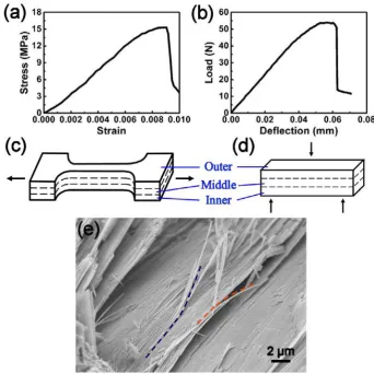
Figure 3.1. Inelastic deformation of conch shells. (a) A representative stress-strain curve upon tension with the loading direction showed in (c). (b) A load-deflection curve of three-point bending with the oriented loading displayed in (d). (c) Fracture morphology of the bended sample. The curved third-order lamellae clearly indicate the occurrence of plastic deformation.
Displayed in Figures 3.1a and b, conch shells yielded after the preliminary elastic
response upon both tensile and bending conditions. The occurrence of bulk inelasticity
redistributes stress and realizes the high fracture toughness of bioceramics. It is generally
of lamellae in virtue of the interlayer features, i.e., lamellar nano-asperities, biopolymer
bond.51,52,85 Surprisingly, we found curved third-order lamellae (Figure 1c) with bending
strain up to ~ 0.7 % (calculated in Equation 3.186) in the fractured specimen:
% 100 ) ( + × = R r r
ε 3.1
where r and R are the half thickness of lamella and radius of bending curvature, respectively. This nonreversible curvature suggests the plastic deformation of
ceramic-based third-order lamellae, which has never been reported before. Therefore,
lamellae not only deflect cracks into 'easy' interlayer but also perform plasticity to shield
cracks from breaking through directly, contributing greatly to the exhibited inelasticity as
well as robustness. Our new findings overturn the inherent cognition of brittleness in
bioceramics. To validate the observation, nanoscale three-point bending tests were
carried out on individual third-order lamellae.
On basis of the nanoscale three-point bending (Figure 3.2a), elastic modulus (E) of lamella with two ends fixed can be calculated as:87,88
I L k I d FL E n n 192 192 3 3 =
= 3.2
where I is the moment of inertia, determined as I =bh3/12 for the rectangular cross section, b and h represent width and height of tested lamella, respectively. F is the applied load; the suspended length of lamella is denoted as L. Spring constant of lamella (kn) is obtained as followed:87,88
2 1 2 1 k k k k
where the quantities k1 and k2 are determined by slopes of Force - Piezo Z position curves
upon indenting lamellae non-suspended and suspended over the trench, separately. Based
on the experimental results in this work, elastic modulus (E = 96 ± 8 GPa) of third-order lamellae is hereby obtained for the first time.
In comparison with well-rounded third-order lamella before bending (Figures 3.2b
and c), the appealing phenomena of necking and high-angle kink at 340 demonstrate the
metal-like plastic deformation of lamella upon external loading. The calculated ~ 0.7%
bending strain86 from Figure 3.2e is consistent well with the finding in Figure 3.1c. In
view of strain-rate-dependence performance of bulk shells and other reported
nanomaterials,49,89 our bending strain rate at 100 /s (based on the AFM tip approaching
speed and sample dimension) triggers us to investigate: What is the metallic performance
under much lower strain rate?
As illustrated in Figures 3.3a - f, an in situ bending test was carried out under TEM observation. Generated via shrinking the supporting film upon electron beam
irradiation,90 the studied lamella was steadily forced to bend at a lower strain rate (~ 10-3
/s) compared to that of AFM bending. The achieved bending strain at 9.1 % stands in
stark contrast to the aforementioned value (0.7 %) under AFM mode. Despite the
existence of strain-rate performance, such large plastic discrepancy between two loading
conditions seems implausible to be simply compensated by adjusting rates. Considering
the bending condition under electron beam irradiation, the striking electrons might affect
the increment. After closer examination (Figure 3.3g) of the blue boxed area in Figure
3.3e, the angle between (200) planes of two referenced particles (A and B) was veered
from 12.20 to 7.90 (Figure 3.3h) upon elongated 20 s illumination, indicating the role of
electron beam irradiation in bioceramic structural modification. To validate this
Figure 3.4. Phase transformation under in situ irradiation. (a) and (b) TEM images of an individual third-order lamella pre- and post-radiation, respectively. (c - e) Sequential HRTEM images from boxed area of (a) retrieved at the time of T s, T+30 s and T+90 s. Here, T < 60 s for the original focus. (f - h) Corresponding diffraction patterns of (c - e), starting from single crystal characteristic pattern to spotty and continuous Debye rings. Phase transition from aragonite to calcite and finally to lime is, accordingly, derived.
Figures 3.4a and b display the structural evolution of a third-order lamella from
smooth profile to mottled surface under e-beam irradiation. Within 90 s radiation interval,
nanoparticles were steadily driven to rotate (Figures 3.4c - e). Although nanoparticles
diffraction patterns (Figures 3.4f - h) from corresponding Figures 3.4c - e suggests
otherwise. Initially, the single-crystal diffraction pattern identified as aragonite is
displayed in Figure 3.4f. Under additional 30 s illumination (Figure 3.4g), the formation
of calcite (another variety of calcium carbonate confirmed by white arrows) and lime
(CaO, which is characterized as polycrystalline rings) indicate the phase transformation
under e-beam radiation. Finally, both kinds of CaCO3 were decomposed into lime due to
the remaining continuous polycrystalline rings (Figure 3.4h). As a result, the
irradiation-induced phase transformation (aragonite - calcite - lime) is proposed. Herein,
EELS was employed to quantitatively evaluate the variation of elements content under
radiation.
Figures 3.5a and b display the EELS analyses with the spectrum and calculated
element contents of a single third-order lamella, respectively. The listed values are
consistent with the composition of CaCO3. It should first point out that the existence of
carbon film might influence the analyzed results. However, judging by the trend of
changed magnitudes upon irradiation (Figures 3.5c and d), CaCO3 was obviously
decomposed into CaO when subjected to e-beam illumination. Coupling the observation
from Figure 3.4, the suggested phase transformation (aragonite - calcite - lime) induced
by irradiation is verified. Therefore, the improved plasticity in TEM bending (Figure 3.3)
is not only the credit of aragonite, but the contribution from the other two kinds of
ceramics.
How does phase transition happen? Thermal effect is generally related to the issue.
Temperatures for aragonite - calcite and calcite - lime transformations are at around
400 °C and 800 °C, respectively.91,92 Can e-beam illumination heat materials to these
fever levels? Quantitative calculation for evaluating highest temperature by electron
beam heating is listed in the following equation:93,94
) ln 2 1 ( 4 0 0 0 0 r R k l W
T = +
π
3.4where l0 is the thickness of sample (here, 100 nm), k0 is the thermal conductivity (here, 5
W/(m K)), R0 represents the radius of hole in supporting film (here, 10-3 m), and radius of
irradiated region is signified by r0 (here, 100 nm). W is the total absorbed power, and can
2 0 0 0V r
W =
ε
ρ
π
3.5here, ε0 represents proportional absorbed energy (here, 0.01), V is acceleration voltage
(here, 200 keV), ρ0 denotes the current intensity (here, 13.5 A/cm2). Based on the
experimental results of this work, the calculated maximum temperature elevation, 26 K,
within focused area nullifies the heat effect prospection. Associated with
high-thermal-conductivity supporting film, such heating factor is further proved to be
incompetent in guiding phase transformation. Alternatively, we consider the impact effect
of electron particles.
Depending on the transferred energy from striking charged particles to the target
materials, two primary mechanisms of irradiation damage can be triggered by the electron
beam.95,96 Under the sufficient energy, initiation of knock-on damage produces direct
displacement of atoms from the crystal lattice. Otherwise, lattice rearrangement caused
by chemical bonds’ breakage, known as radiolysis, is ascribed to the lower transferred
value. Here, the maximum transferred energy (Emax) from incident electrons with a
certain kinetic energy (E0) to the targeted atom (atomic mass as A) is calculated with the
following equation:97
) 7 . 465 ( ) 10 02 . 1 ( 6 0 max A E E E o × +
= 3.6
Accordingly, the peak transferred values from electron beam to the atoms Ca, C and O
are calculated as 13 eV, 44 eV and 32 eV, respectively, under the condition of 200 kV.
calcium carbonates, relative studies98-100 reveal that radiolysis is quite possible to be the
dominant factor for phase transformation because of the obtained low energies.
Nevertheless, we do not completely exclude the probability of knock-on damage. In CaO,
the much higher displacement energies for Ca and O atoms (~ 50 eV) render knock-on
damage and radiolysis impossible, forming the final stable phase. Then, another question
pumps out: How is the phase transformation crystallographically achieved? Here, the
short-range diffusion induced phase transformation by electron beam is reported, which
consumes the least energy and is regarded as the major mechanism.
Classified as ceramics, aragonite, calcite and lime are characterized as different
crystal structures in orthorhombic, trigonal and face-centered cubic systems, separately.
Due to the identical composition between aragonite and calcite, the phase transition can
be essentially achieved in reshuffling calcium and carbonate ions based on original
aragonite lattice arrangement. Figure 3.6a displays the tracks of ions movement in
aragonite, to be specific, anion groups in neighboring layers are separately rotated at 300
(observed from [001] direction) clockwise and anticlockwise with occupying the
positions half way between two calcium ions from adjacent layers. Meantime, calcium
ions are shifted within a very short distance in the direction of [010] (and [010]).32 Via
small distortive deformation afterwards for lattice accommodation because of the lattice
dissimilarities between two calcium carbonates, the transformation process from
Figure 3.6. Sketches of lattice evolution during phase transformation. (a) Aragonite lattice observing from [100] direction. (b) Lattice arrangement of calcite from [110] direction. (c) Calcite crystal lattice in [104] inspection. (d - g) Four sorts of orientations and ionic adjustments in calcite that lead to the formation of lime. (h - k) Corresponding stable structures of lime evolving from (d - g).
Similarly, the short-range movement upon transformation (calcite - lime) depends
Figure 3.6c, the trigonal structure (aligned in (104) plane) of calcite is altered to
face-centered cubic organization (lime) by slightly moving ions in the direction of [401]
(and [401]), substituting planes of O2- for CO32- upon CO2 escaping, as well as the
occurrence of small lattice-distortive deformation to adjust the new-formed lattice
variation (Figures 3.6d and h). Additionally, such decomposition can be realized in the
parallel approach via shuffling along [010] (and [010]), [441] (and [441]) and
] 1 48
[ (and [481]), respectively (Figures 3.6e - g, i - k).
However, this critical question in e-beam promoting the plasticity of bioceramics
remains unsettled. It should first point out that the lower-rate TEM deformation
contributes to such improvement. More importantly, the cleavage of chemical bonds
(radiolysis) and resulting creation of vacancies induced by electron beam irradiation
increase ions migration and rotation, facilitating the bond-switching process which
repairs the new triggered voids upon deformation. Such self-promoted accommodation to
stress flow accompanied by the assistance of biopolymer’s viscosity and nascent
nanoparticle refinement realize the metal-like performance upon e-beam radiation.
3.3 SUMMARY
In summary, we demonstrate direct evidence that the ceramic-based third-order
lamellae, which are the building blocks in conch shells, exhibit not only elasticity but also
plasticity, overturning the general assumption of brittleness. The nanoparticle-biopolymer
construction of third-order lamellae contributes to this metal-like behavior with the
bioceramics is improved by the electron-beam induced phase transformation (aragonite -
calcite - lime). These findings deepen our understanding of the toughening strategy of
conch shells and may open up new avenues for developing bioinspired materials and
CHAPTER 4
D
YNAMICALS
ELF-S
TIFFENINGP
ROTECTION INC
ONCHS
HELLSCreatures have been incubating countless skills for survival (i.e., predation and
self-protection). Conch shells, as called as nature’s armors, protect the soft bodies from
predatory attacks (such as turtles, crabs, fish, and seabirds).101,102 Harassed by daily
ballistic attacks, what roles does multiscale organization play in the shielding of soft
bodies? Could such shells initiate alternative mechanisms as a response in comparison
with those executed upon quasi-static conditions? Can we blend their fracture behaviors
into man-made bio-inspired103 composites? Addressing these questions needs our
in-depth investigation in bridging relationship between materials’ structure and
performance under different strain rate situations.
Accordingly, a series of uniaxial compression tests under quasi-static and
dynamical loading rates were designated for the aforementioned scenarios. We utilized
the universal testing machine to perform quasi-static compression (10-4 ~ 10-2 /s), and
Split Hopkinson Pressure Bar System to realize high strain loading rates (~ 103 /s). The
elevated fracture strength and damage tolerance under dynamic loading stands in stark