ABSTRACT -This paper presents a unique approach for coding of speech signal by using wavelet Packet Decomposition. A key technology that enables speech and audio signals with less mass storage device and bandwidth is coding technique. It will be enforced effectively by Wavelet Packet Transform (WPT) using different threshold methods i.e. global dependent and level dependent. The performance of those threshold methods using wavelet Packet Decomposition in speech signal coding is presented along with the different types of wavelets like Dabauchies (db1-db10) at different levels of decomposition(Level 1-level 4). Further the performance analysis of the threshold methods are compared in terms of percentage of zero coefficients and retained signal energy using wavelet transform and wavelet Packet decomposition.
Keywords: Coding, Wavelet Packet Decomposition Wavelet threshold methods, Wavelets, Percentage of zero coefficients, retained signal energy.
I. INTRODUCTION
Since speech signal contains more number of redundant data, how to compress speech signal by maintaining prime quality at low bit rates is still a very important topic. In order to reduce redundancy and make full use of the human’s auditive masking effect by using a variety of source coding techniques, not only can compress the coding rate by many times, but also has the ability to regain high intelligibility and acceptability of speech signals[1,2]. Coding is a process of converting an input data into another data that has a smaller size. Coding is possible only because data is normally represented in the computer in a format that is longer than necessary i.e. the input data has some amount of redundancy associated with it. The main objective of coding systems is to eliminate this redundancy.
When coding is used to reduce storage requirements, overall program execution time may be reduced. This is because reduction in storage will result in the reduction of disc access attempts. With respect to transmission of data, the data rate is reduced at the source by the compressor, it is then passed through the communication channel and returned to the original rate by the expander at the receiving end. The coding algorithms help to reduce the bandwidth requirements and also provide a level of security for the data being transmitted. In most of the cases, direct methods are superior than transform based methods with respect to its system simplicity and
error. The transform methods usually achieve higher coding ratio compared to direct
method. Compressor using wavelet packet (WP) based techniques are efficient than discrete wavelet transform (DWT) based method for Time Series coding.
Therefore, a speech coding system focuses on reducing the amount of redundant data while preserving the integrity of signals. Since speech signal is a non-stationary signal, consists of time varying spectral components. Fourier Transform only provides what spectral components exist , not where in time they are located. Need some other ways to determine time localization of spectral components.
The different transformation of speech signals from time to frequency domains for the purpose of coding aim at representing them with the minimum number of coding parameters. [1, 2] Speech is non-linear random process. Wavelet transform devotes a lot to deal with time-varying, non-stationary signal. Wavelet transform has excellent resolution in both time and frequency domain [10]. Wavelet transform with detail of signal, decomposes the high-frequency, and the signal was decomposed to the time-frequency space which has a certain correspondence with critical band of speech. The result of wavelet transform is called “wavelet coefficients” [6]. In [3, 4] the coefficient conversion of wavelet can classify into two types, Continuous Wavelet Transform (CWT) and Discrete Wavelet Transform (DWT). This article investigates the improvement speech coding technique based on the model wavelet transform which is focused in the frequency lossless. There are some related researches works which used wavelet transform for speech coding. The DWT is used as a tool for Hindi speech recognition is presented in [5]. It studies the recognition of isolated words in Hindi Language speech. The mother wavelets are selected to use 3 families, Daubehies (db), Coiflets (coif) and Discrete Meyer Wavelet (dmey). It is found that Daubechies 10, 5-level decomposition and the Discrete Meyer wavelet give comparable performance, while the Daubechies 8, 3-level decomposition provides the poorest performance. An innovative method for speech coding by detecting the end points of the speech signals prior to compressing was proposed in [6].
In [7] applies the Wavelet Packet Transform (WPT) to process speech signal to obtain optimal wavelet tree to allocate the dynamic bits, and then uses the modified Set Partitioning in Hierarchical Trees (SPIHT) coding algorithm to compress the coefficients from the wavelet packet transform. It indicates that it can gain better high coding. However the quality signal reconstruction is still
SPEECH SIGNAL CODING FOR VOIP APPLICATIONS USING
WAVELET PACKET TRANSFORM
A
N.Rama Tej Nehru,
BP.Sunitha
AM.Tech student,
BAssoc. Professor.
Department of ECE, Pragati Engineering College, A.P,
India.
not perfect according to loss of frequency. Thus this article is concerned to compare the frequency lossless of the new model wavelet for speech coding.
This paper is organized by various sections, section-II describes to brief introduction to DWT, Section – III gives Wavelet Packet Decomposition, Section IV Wavelet Packet Based Speech Coding Technique, section – V gives Results and discussion, section – VI describes conclusion followed by References.
II. INTRODUCTION TO DWT
Similar to the Fourier series expansion, the DWT maps a continuous variable Ψ(t) into a sequence of coefficients, the resultant coefficients are called discrete wavelet transform of Ψ(t). Its representation involves the decomposition of the signals in wavelet basis function Ψ(t) given by
Ψa,b(t)= [(t-b)/a] a, b ε R -(1)
Where a, b are called scale and position parameters as respectively HPF CD High Frequency 2 s(t) LPF CA Low Frequency
Fig 1: Single level wavelet decomposition (analysis).
The multi resolution analysis is given by S. Mallet and Mayer proves that any conjugate mirror filter characterizes a wavelet Ψ. The wavelet decomposition of a signal x(t) based a multi resolution theory can be obtained using filter [10], the filter based wavelet decomposition is shown in fig. 1.
The above arrangement has used two wavelet decomposition filters which are high pass and low pass respectively followed by down sampling by 2 producing half input data point of high and low frequency. The high frequency coefficients (CD) and low frequency coefficients are called approximate coefficients (CA). The signal can be reconstructed back by inverse wavelet transform. The corresponding filter bank structure for reconstruction is shown in figure 2. HPF CD s(t) LPF CA
Fig 2: single level wavelet reconstruction (synthesis) III. INTODUCTION TO WAVELET PACKET
TRANSFORM
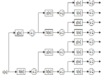
It is a wavelet transform where the discrete-time or sample signal is passed through more filters than the discrete wavelet transform (DWT).In the DWT, each level is calculated by passing only the previous wavelet approximation coefficients through discrete-time low and high pass quadrature mirror filters. However in the WPD, both the detail and approximation coefficients are decomposed to create the full binary tree. For n levels of decomposition the WPD produces 2n different sets of coefficients (or nodes) as opposed to (3n + 1) sets for the DWT. However, due to the down sampling process the overall number of coefficients is still the same and there is no redundancy.
From the point of view of coding, the standard wavelet transform may not produce the best result, since it is limited to wavelet bases that increase by a power of two towards the low frequencies. It could be that another combination of base produces a more desirable representation for a particular signal. The best basis algorithm finds a set of bases that provide the most desirable representation of the data relative to a particular cost function. There were relevant studies in signal processing and communications fields to address the selection of sub band trees (orthogonal basis) of various kinds, e.g. regular, dyadic, irregular, with respect to performance metrics of interest including energy. Compaction e.g. entropy, sub band correlations and others. Discrete wavelet transform theory or continuous in the variable offers an approximation to transform discrete or sampled signals. In contrast, the discrete sub band transform theory provides a perfect representation of discrete signals.
Fig3: Wavelet Packet Decomposition over 3 levels. Where g[n] & h[n] are low-pass approximation & high-pass detail
coefficients.
2
2
IV. WAVELET PACKET BASED SPEECH CODING TECHNIQUE
The idea behind signal coding using wavelet packets is primarily linked to the relative Scarceness of the wavelet domain representation for the signal. Wavelets concentrate speech information (energy and perception) into a few neighboring coefficients. Therefore as a result of taking the wavelet transform of a signal, many coefficients will either be zero or have negligible magnitudes. Another factor that comes into picture is taken from psychoacoustic studies. Since our ears are more sensitive to low frequencies than high frequencies and our hearing threshold is very high in the high frequency regions, we used a method for coding by means of which the detail coefficients (corresponding to high frequency components) of wavelet transforms are thresholded such that the error due to thresholding is in audible to our ears. Since some of the high frequency components are discarded, we should expect a smoothened output signal
A) Choice of Wavelet:
The choice of the mother- wavelet function used in designing high quality speech coders is of prime importance. Several different criteria can be used in selecting an optimal wavelet function. The objective is to minimize reconstructed error variance and maximize signal to noise ratio (SNR). In general optimum wavelets can be selected based on the energy conservation properties in the approximation part of the wavelet coefficients. A suitable criterion for selecting optimum mother wavelets is related to the amount of energy a wavelet basis function can concentrate into the level 1 approximation coefficients.
B) Wavelet Packet Decomposition:
Wavelets work by decomposing a signal into different resolutions or frequency bands, and this task is carried out by choosing the wavelet function and computing the Wavelet Packet Transform (WPT) . Signal coding is based on the concept that selecting a small number of approximation coefficients (at a suitably chosen level) and some of the detail coefficients can accurately represent regular signal components. Choosing a decomposition level for the WPT usually depends on the type of signal being analyzed or some other suitable criterion such as entropy.
C) Truncation of Coefficients:
After calculating the wavelet transform of the speech signal, coding involves truncating wavelet coefficients below a threshold. From the experiments that we conducted, we found that most of the coefficients have small magnitudes. Speaking in general terms, more than 90% of the wavelet coefficients were found to be insignificant, and their truncation to zero made an imperceptible difference to the signal. This means that most of the speech energy is in the high - valued coefficients, which are few. Thus the small valued coefficients can be truncated or zeroed and then be used to reconstruct the signal.
Two different approaches are available for calculating thresholds:
1. Global threshold:
It involves taking the wavelet expansion of the signal and keeping the largest absolute value coefficients. In this case you can manually set a global threshold, a coding performance or a relative square norm recovery performance. Thus, only a single parameter needs to be selected. The coefficient values below this value should be set to zero, to achieve coding. Figure4 shows the setting of global threshold for a typical speech signal.
Fig4: Global thresholding of a speech signal
In this figure, the X- axis represents the coefficient values .The black (dark) vertical line moves to right or left, thereby changing the threshold. The intersection of this line with green line indicates the percentage of zero coefficients below this threshold. Its intersection with the red line indicates the percentage of signal energy retained after truncating these coefficients to zero.
2. Level dependent thresholding:
This approach consists of applying visually determined level dependent thresholds to each decomposition level in the Wavelet Transform The following figure shows the level - dependent thresholding. The truncation of insignificant coefficients can be optimized when such a level dependent thresholding is used.
Fig5: Level dependent thresholding of a speech signal
.
Stop
Decompressed speech signal
Encoding Signal coding is achieved by first truncating small - valued coefficients and then efficiently encoding them. One way of representing the high- magnitude coefficients is to store the coefficients along with their respective positions in the wavelet transform vector.
Fig6: Proposed Speech Coding Technique using Wavelet Transform
V. RESULTS AND DISCUSSIONS
This paper compares the performance analysis of wavelet threshold methods in coding of speech signal using Wavelet form and Wavelet Packet Transform. Threshold methods have been applied on the speech signal spoken in English language, taken from a female speaker at a sampling frequency of 8 KHz. All the threshold methods are tested with wavelets like Dabauchies (db1-db10)at four different levels of decomposition i.e. level1,level2,level3,level4. Further the performance analysis of the threshold methods are compared in terms of percentage of zero coefficients, retained signal energy.
A) Performance Measures 1. Retained signal energy:
This indicates the amount of energy retained in the compressed signal as a percentage of the energy of original signal. When compressing using orthogonal wavelets, the Retained energy in percentage is defined by:
Where x and e are respectively the mean square of the speech signal and the mean square difference between the original and reconstructed signals.
2. Percentage of zero coefficients: It is given by the following relation:
. RE (%) = - (2) % of Zeros = - (3) Storage (Or) Transmissi on Channel Select a threshold and truncate the
coefficients sound file from Construct the
the samples Decode the Stored (or) received signal Start Read A Source File Perform wavelet packet decomposition of the signal a specified level Select a suitable encoding technique to truncate the coefficients Apply the inverse wavelet packet to reconstruct the speech samples Decompressed speech signal Stop
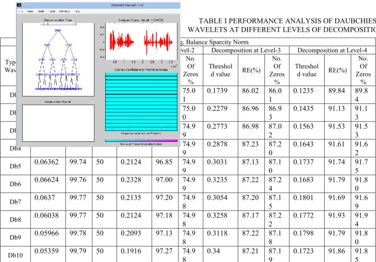
TABLE I PERFORMANCE ANALYSIS OF DAUBCHIES WAVELETS AT DIFFERENT LEVELS OF DECOMPOSITIONS
IN TERMS OF THRESHOLD VALUE, RETAINED ENERGY (RE %) AND NUMBER OF ZEROS WITH GLOBAL THRESHOLDING BY BALANCE SPARCITY NORM
TABLE II PERFORMANCE ANALYSIS OF DAUBCHIES WAVELETS AT DIFFERENT LEVELS OF DECOMPOSITIONS IN TERMS OF THRESHOLD VALUE, RETAINED ENERGY (RE %) AND NUMBER OF ZEROS WITH GLOBAL
THRESHOLDING BY REMOVAL NEAR ZERO Global Thresholding, Removal Near Zero
Type of Wavelet
Decomposition at Level-1 Decomposition at Level-2 Decomposition at Level-3 Decomposition at Level-4 Threshold value RE(%) No. Of Zeros % Threshold value RE(%) No. Of Zeros % Threshold value RE(%) No. Of zeros % Threshold value RE(%) No. Of Zeros % Db1 0.00418 6 99.98 25.0 5 0.00418 6 99.97 32.0 6 0.00418 6 99.97 34.27 0.00418 6 99.97 35.0 5 Db2 0.00418 6 99.97 30.8 5 0.00418 6 99.97 38.6 3 0.00418 6 99.96 40.90 0.00418 6 99.96 41.8 6 Db3 0.00418 6 99.97 34.0 3 0.00418 6 99.96 41.9 5 0.00418 6 99.96 44.34 0.00418 6 99.96 45.2 2 Db4 0.00418 7 99.97 35.5 5 0.00418 7 99.96 43.7 8 0.00418 7 99.96 46.25 0.00418 7 99.96 47.0 0 Db5 0.00418 6 99.97 36.1 5 0.00418 7 99.96 44.5 2 0.00418 7 99.96 46.80 0.00418 7 99.96 47.6 6 Db6 0.00418 7 99.97 36.6 1 0.00418 7 99.96 44.7 6 0.00418 7 99.96 47.18 0.00418 7 99.96 48.1 4 Db7 0.00418 6 99.77 37.2 3 0.00418 6 99.96 45.1 8 0.00418 6 99.96 47.49 0.00418 6 99.96 48.2 9 Global Thresholding, Balance Sparcity Norm
Type of Wavelet
Decomposition at Level-1 Decomposition at Level-2 Decomposition at Level-3 Decomposition at Level-4 Threshol d value RE(%) No. Of Zeros % Threshol d value RE(%) No. Of Zeros % Threshol d value RE(%) No. Of Zeros % Threshol d value RE(%) No. Of Zeros % Db1 0.1632 97.11 50.0 2 0.3532 87.68 75.01 0.1739 86.02 86.01 0.1235 89.84 89.84 Db2 0.0831 99.28 50 0.2963 94.26 75.0 0 0.2279 86.96 86.93 0.1435 91.13 91.13 Db3 0.05256 99.60 50 0.2931 95.98 74.9 9 0.2773 86.98 87.02 0.1563 91.53 91.53 Db4 0.05049 99.70 50 0.2847 96.69 74.9 9 0.2878 87.23 87.20 0.1643 91.61 91.62 Db5 0.06362 99.74 50 0.2124 96.85 74.9 9 0.3031 87.13 87.10 0.1737 91.74 91.75 Db6 0.06624 99.76 50 0.2328 97.00 74.9 9 0.3235 87.22 87.24 0.1683 91.79 91.80 Db7 0.0637 99.77 50 0.2135 97.20 74.9 8 0.3054 87.20 87.15 0.1801 91.69 91.69 Db8 0.06038 99.77 50 0.2124 97.18 74.9 8 0.3258 87.17 87.22 0.1772 91.93 91.94 Db9 0.05966 99.78 50 0.2093 97.13 74.9 8 0.3118 87.22 87.18 0.1798 91.79 91.80 Db10 0.05359 99.79 50 0.1916 97.27 74.9 8 0.34 87.21 87.19 0.1723 91.86 91.85
Db8 0.00418 7 99.97 37.3 1 0.00418 7 99.96 45.7 8 0.00418 7 99.96 48.17 0.00418 7 99.96 49.0 1 Db9 0.00418 6 99.97 37.3 3 0.00418 6 99.96 45.4 3 0.00418 6 99.96 47.93 0.00418 6 99.96 48.8 2 Db10 0.00418 7 99.97 37.5 1 0.00418 7 99.96 45.4 8 0.00418 7 99.96 47.86 0.00418 7 99.96 48.6 7 TABLE III PERFORMANCE ANALYSIS OF DAUBCHIES WAVELETS AT DIFFERENT LEVELS OF DECOMPOSITIONS IN TERMS OFTHRESHOLD VALUE, RETAINED ENERGY (RE %) AND NUMBER OF ZEROS
WITH WAVELET PACKET TRANSFORM BY BALANCE SPARCITY NORM Wavelet Packet Transform, Balance Sparcity Norm
Type of Wavelet
Decomposition at Level-1 Decomposition at Level-2 Decomposition at Level-3 Decomposition at Level-4 Threshol d value RE(%) No. Of Zeros % Threshol d value RE(%) No. Of Zeros % Threshol d value RE(%) No. Of zeros % Threshol d value RE(%) No. Of Zeros % Db1 0.1632 97.11 50.0 2 0.3532 87.68 75.01 0.1775 86.05 86.05 0.1236 90.06 90.06 Db2 0.0831 99.28 50 0.2963 94.26 75.0 0 0.2342 86.96 86.96 0.1378 91.32 91.32 Db3 0.05256 99.60 50 0.2931 95.98 75.0 0 0.2798 87.03 87.03 0.1592 91.77 91.78 Db4 0.05049 99.70 50 0.2847 96.69 75.0 0 0.2938 87.26 87.22 0.1689 91.89 91.88 Db5 0.06362 99.74 50 0.2124 96.85 75.0 0 0.3031 87.12 87.13 0.1789 92.08 92.08 Db6 0.06624 99.76 50 0.2328 97.00 75.0 0 0.3126 87.31 87.26 0.1767 92.11 92.11 Db7 0.0637 99.77 50 0.2135 97.20 75.0 0 0.3054 87.18 87.18 0.1796 92.01 92.01 Db8 0.06038 99.77 50 0.2124 97.17 75.0 0 0.3224 87.25 87.25 0.1763 92.24 92.23 Db9 0.05966 99.78 50 0.2093 97.12 75.0 0 0.3118 87.20 87.22 0.1883 92.16 92.14 Db10 0.05359 99.79 50 0.1916 97.26 75.0 0 0.34 87.19 87.24 0.1821 92.16 92.15
TABLE IV PERFORMANCE ANALYSIS OF DAUBCHIES WAVELETS AT DIFFERENT LEVELS OF
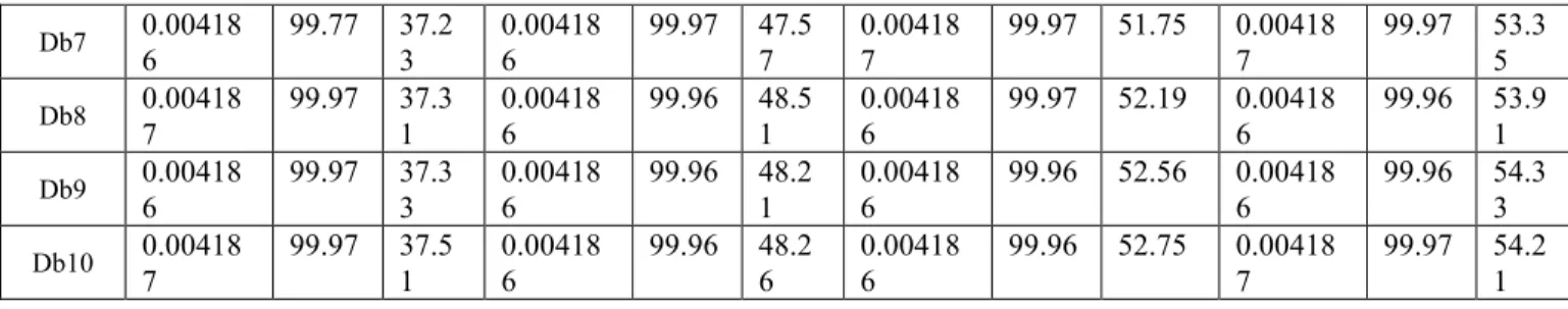
DECOMPOSITIONS IN TERMS OF THRESHOLD VALUE, RETAINED ENERGY (RE %) AND NUMBER OF ZEROS WITH WAVELET PACKET TRANSFORM BY REMOVAL NEAR ZERO
Wavelet Packet Transform , Removal Near Zero
Type of Wavelet
Decomposition at Level-1 Decomposition at Level-2 Decomposition at Level-3 Decomposition at Level-4 Threshold value RE(%) No. Of Zeros % Threshold value RE(%) No. Of Zeros % Threshold value RE(%) No. Of zeros % Threshold value RE(%) No. Of Zeros % Db1 0.00418 6 99.98 25.0 3 0.00418 1 99.97 32.2 2 0.00418 6 99.97 35.79 0.00418 9 99.97 36.4 2 Db2 0.00418 6 99.97 30.8 5 0.00418 6 99.97 39.5 8 0.00418 6 99.97 42.90 0.00418 6 99.96 44.9 1 Db3 0.00418 6 99.97 34.0 3 0.00418 7 99.96 43.5 4 0.00418 6 99.97 46.96 0.00418 7 99.96 49.2 7 Db4 0.00418 7 99.97 35.5 5 0.00418 6 99.96 46.1 4 0.00418 7 99.97 49.84 0.00418 6 99.96 51.0 5 Db5 0.00418 6 99.97 36.1 5 0.00418 7 99.96 47.1 6 0.00418 6 99.97 50.83 0.00418 6 99.97 51.8 8 Db6 0.00418 7 99.97 36.6 1 0.00418 6 99.96 47.2 1 0.00418 6 99.97 50.89 0.00418 6 99.97 52.8 4
Db7 0.00418 6 99.77 37.2 3 0.00418 6 99.97 47.5 7 0.00418 7 99.97 51.75 0.00418 7 99.97 53.3 5 Db8 0.00418 7 99.97 37.3 1 0.00418 6 99.96 48.5 1 0.00418 6 99.97 52.19 0.00418 6 99.96 53.9 1 Db9 0.00418 6 99.97 37.3 3 0.00418 6 99.96 48.2 1 0.00418 6 99.96 52.56 0.00418 6 99.96 54.3 3 Db10 0.00418 7 99.97 37.5 1 0.00418 6 99.96 48.2 6 0.00418 6 99.96 52.75 0.00418 7 99.97 54.2 1 TABLE V ENTROPY VALUES AT DIFFERENT LEVELS
OF DECOMPOSITION
S.No Name of the Signal Samples No. of Entropy
1 Original Signal 384000 1345.3
2 Approximation at Level-1 (CA1) 192000 1119.1 3 Detail at Level-1 (CD1) 192000 14.08 4 Approximation at Level-2 (CA2) 96000 886.41 5 Detail at Level-2 (CD2) 96000 33.14 6 Approximation at Level-3 (CA3) 48000 656.61 7 Detail at Level-3 (CD3) 48000 60.602 8 Approximation at Level-4 (CA4) 24000 449.39 9 Detail at Level-4 (CD4) 24000 91.771 A comparative analysis has been performed between the threshold methods, for different wavelets with different levels of decomposition as shown in tables I,II,III&IV in terms of percentage of zero coefficients, signal energy in the first level approximation, retained signal energy.
It is observed as the level of decomposition is increased from level 1 to level-4, the percentage amount of retained energy will goes on decreasing and %of zero coefficients are increasing. We can also observe that as the level of decomposition increases we can achieve a higher coding factor which means that requires less memory space and band width. Generally higher coding factors are preferable but in the reconstruction process we may lose some information.
VI. CONCLUSION
In this paper the performance analysis of different wavelet threshold methods in coding of speech signal is investigated along with 4 different levels of decomposition along with Dabauchies (db1-db10) wavelets. The result shows that as the level of decomposition increases the percentage amount of retained energy will goes on decreasing and percentage of of zero coefficients are increasing. Thus the lower levels of decomposition can be preferred as seen from the result performance.
REFERENCES
[1] Goudarzi, M.M, and Moradi , H. M., 2005, “Electrocardiogram signal coding Using multiwavelet transform,” Transactions on Engineering, Computing and Technology
[2] Benzid, R., Marir, F., and Bouguechal, N. E., 2006, “Qualitycontrolled coding method using wavelet transform for electrocardiogram signals,” International Journal of Biomedical Science.
[3] Benzid, R., Marir, F., Benyoucef, M., and Arar, D., 2003, “Fixed percentage of wavelet coefficients to be zeroed for ECG coding “Electronics Letters Vol 39 No 11.
[4] Chen, J., Itoh, S., and Hashimoto, T., 1993, “ECG data coding by using wavelet transform,”IEICE Trans.Inform.SystemDjohan, [5] T. Q. Nguyen, and W. J. Tompkins, “ECG coding using discrete
symmetric wavelet transform,”in Proc. 17th Int. Conf. IEEE Med. Biol., vol. 1.
[6] K. Uyar and Y. Z. Ider, “Development of a coding algorithm suitable for exercise ECG data,” in Proc. 23rd Annu. EMBS Int. Conf., Oct. 2001.
[7] A. Reza, A. Moghaddam, and K. Nayebi, “A two dimensional wavelet packet approach for ECG coding,” in Proc. Int. Symp. Signal Pro-cessing Applications, Aug. 2001
[8] S. Bhavani, K. Thanushkodi, “A Survey on Coding Algorithms in Medical Image Coding”, International Journal on Computer Science and Engineering.
[9] G. K. Kharate, V. H. Pati, “Color Image Coding Based On Wavelet Packet Best Tree”, International Journal of Computer Science. [10] A. Othman Khalifa, “Wavelet Coding Design for Image Data
Coding”, The International Arab Journal of Information Technology, Vol. 6, No. 2, pp. 118-127, April 2009.
[11] Alice Blessie1, J. Nalini and S.C.Ramesh, “Image Coding Using Wavelet Transform Based on the Lifting Scheme and its Implementation”, IJCSI International Journal of Computer Science Issues, Vol. 8.
Authors Profile:
P.Sunitha born on April 3rd 1983 in Krishna district,received the B.Tech
degree in Electronics and
Communication Engineering from JNTU college of Engineering , Kakinada in 2006 and M.Tech in Digital Electronics and Communication Systems (DECS) from JNTU Kakinada. She is working towards the Ph.D degree from JNTUK.