172
Particle Swarm Optimization Used To Tuned The PID Controller For
Load Frequency Control of Power System
Abstract: The objective of this work is introducing the particle swarm optimization technique for tuning of PID
controller which is used to reduce the area control error and to
minimize the frequency deviation of single area system and
two area systems. These works establish a Mat lab simulink
Model for single area control as well as two area control
system. In this work a global search technique PSO is used to
find optimum solution. PSO is an optimization technique
based on the social behavior like fish schooling, can provide
global solution of the nonlinear problem.
Keywords PSO, Generation control, PID controller, single area and two area control system.
1.
Introduction
The main objective of power system operation and control is
to maintain continuous supply of power with an acceptable
quality, to all the consumers in the system. The system will be
in equilibrium, when there is a balance between the power
demand and the power generated. As the power in AC form
has real and reactive components: the real power balance; as
well as the reactive power balance is to be achieved. There are
two basic control mechanisms used to achieve reactive power
balance (acceptable voltage profile) and real power balance
(acceptable frequency values). The former is called the
automatic voltage regulator (AVR) and the latter is called the
automatic load frequency control (ALFC) or automatic
generation control (AGC). AGC provides an effective
mechanism for adjusting the generation to minimize frequency
deviation and regulate tie-line power flows. The AGC system
realizes generation changes by sending signals to the
under-control generating units. The AGC performance is highly
dependent on how those generating units respond to the
commands. The generating unit response characteristics are
dependent on many factors, such as type of unit, fuel, control
strategy, and operating point. Article [1] presented real time
simulation to analyze the behavior of discrete controller for
interconnected power system. This work two-area
interconnected power system consisting of non-identical
power plants with EHVAC transmission link as
interconnection is considered for investigations. Hasan
Bevrani et al. [2] described AGC as one of the important
control problems in interconnected power system design and
operation are becoming more significant today due to the
increasing size, changing structure, emerging renewable
energy sources and new uncertainties, environmental
constraints, and complexity of power systems. The potential
applications of the SMES technology in electrical power and
energy systems [4] described. A new method for determine the
optimal tuning of the PID controller parameter of an AVR
system using Modified particle swarm optimization (MPSO)
algorithm [5]. S. P. Ghoshal et al. [6] described automatic
generation control with interconnected two-area multiple-units
hydro–hydro system is investigated. Such a hydro dominated
system is dynamically unstable. A control strategy using
controlling the phase angle of TCPS is proposed for provide
active control facility of system frequency Also, the optimum
adjustment of PID controller's parameters in a robust way
under bilateral contracted scenario following the large step
load demands and disturbances with and without TCPS are
Sharda Singh Tomar M. Tech. Scholar (Power System)
TIT, Bhopal [email protected]
Pallavi Bondriya Associate Professor
TIT, Bhopal
173
investigated by Particle Swarm Optimization (PSO), that has a
strong ability to find the most optimistic results [7]. Zwe-Lee
Gaing et al [20] explained a novel design method for
determining the optimal proportional-integral-derivative (PID)
controller parameters of an AVR system using the particle
swarm optimization (PSO) algorithm is presented. Demiroren
et al in [27] described a self-tuning control scheme is proposed
and applied to automatic generation control (AGC) in power
system with superconducting magnetic energy storage
(SMES). The system is assumed consisting of two areas. The
proposed self-tuning control scheme is used to implement the
automatic generation control adding to conventional control
configuration.
2.
Generator Voltage Control System
The voltage of the generator is proportional to the speed and
excitation (flux) of the generator. The speed being constant,
the excitation is used to control the voltage. Therefore, the
voltage control system is also called as excitation control
system or automatic voltage regulator (AVR).For the
alternators, the excitation are provided by a device (another
machine or a static device) called exciter.
Fig.1. a simplified block diagram of Voltage (Excitation)
Control System
2.1. Automatic Load frequency Control
The main functions of the ALFC are to: I) to maintain the
steady frequency; ii) Control the tie-line flows; and iii)
Distribute the load among the participating generating units.
Fig.2: The Schematic representation of ALFC system
Fig.3. the block diagram representation of the ALFC
2.2. AGC in a Single Area System
In a single area system, there is no tie-line schedule to be
maintained. Thus the function of the AGC is only to bring the
frequency to the nominal value. This will be achieved using
the supplementary loop (as shown in Fig.4).Which uses the
integral controller to change the reference power setting so as
to change the speed set point. The integral controller gain KI
needs to be adjusted for satisfactory response (in terms of
overshoot, settling time) of the system.
Fig.4: The block diagram representations of the AGC for
174
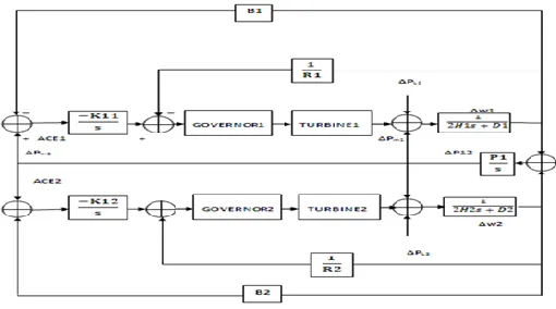
2.3. AGC in a Multi Area System
In a multi area control system, there will be one ALFC loop
for each control area as shown in fig. 5
.
Fig.5. AGC for a multi-area operation
3. Problem formulation
TIE‐LINE BIAS CONTROL: In this control strategy each
area of an interconnected system tries to regulate its area
control error (ACE) to zero, where: ACE=(Ta- Ts) -10β(fa- fs)
Where (Ta- Ts) = Difference between the actual and the
scheduled net interchange on the Tie lines, (fa- fs) = Frequency
Error and β= 1/R + D. The control error for each area is a
linear combination of tie-line power and frequency errors and
can be expressed as shown
ACE1 = ΔP1-2 + B1Δf1 ACE2 = ΔP2-1 + B2Δf2
The signals to the respective speed changers will, therefore, be
of the following type
ΔPref 1= -KI1∫ (ΔP1-2 + B1Δf1) dt
ΔPref 2= -KI2∫ (ΔP1-2 + B2Δf2) dt
Where B1 and B2 represent tie line bias parameters; and KI1
and KI2 are integrator gains. The area control error (ACE) is
indicative of the total interchange of power for multi area
control is given as the follows;
ACEk = Σ (ΔPij + BkΔfk)
3.1. Super Conducting Magnetic Energy Storage
System (SMES)
The real power as well as the reactive power can be absorbed
by or released from the SMES coil according to system power
requirements. The one major advantage of the SMES coil is
that it can discharge large amounts of power for a small period
of time. Also, unlimited number of charging and discharging
cycles can be carried out.
Fig. 6 Single area system with SMES unit
4.
Particle Swarm Optimization
Particle Swarm Optimization (PSO) is a technique used to
explore the search space of a given problem to find the
settings or parameters required to maximize a particular
objective. This technique, first described by James Kennedy
and Russell C. Eberhart in 1995 [1], originates from two
separate concepts: the idea of swarm intelligence based off the
observation of swarming habits by certain kinds of animals
(such as birds and fish); and the field of evolutionary
computation. The PSO algorithm works by simultaneously
maintaining several candidate solutions in the search space.
During each iteration of the algorithm, each candidate solution
is evaluated by the objective function being optimized,
determining the fitness of that solution. Each candidate
solution can be thought of as a particle “flying” through the
fitness landscape finding the maximum or minimum of the
objective function. Initially, the PSO algorithm chooses
candidate solutions randomly within the search space. The
PSO algorithm consists of just three steps, which are repeated
until some stopping condition is met. Evaluate the fitness of
each particle. Update individual and global best fitness’s and
positions. Update velocity and position of each particle. The
velocity of each particle in the swarm is updated using the
175
Once the velocity for each particle is calculated, each
particle’s position is updated by applying the new velocity to the particle’s previous position:
x
i(t+1)=x
i(t)+v
i(t+1)
5
Simulation Model and Their Results
5.1.Case Study 1: Single Area Test System
Fig. 7 Simulink model of single area control
For the considered single area test system the PID controller
parameters are optimized using PSO technique. After
optimization results obtained are-
Fig. 8 Frequency Deviation of Single Area System with PSO
based PID controller.
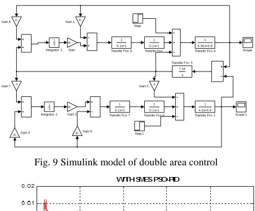
5.2 CASE STUDY 2: TWO AREA TEST SYSTEM
For obtaining better transient response an SMES whose
parameters are optimized using PSO has been incorporated in
the Single area test system with PSO based PID controller.
The structure of frequency stabilizer for SMES is modeled as
the second order lead-lag compensator [4].The objective of
AGC is to reestablish primary frequency regulation, restore
the frequency to its nominal value as quickly as possible and
minimize the tie-line power flows. In order to satisfy above
requirements, the parameters of SMES are needed to be
optimized, which is done by using PSO. The simulation results
of PSO based two area system with optimized SMES is shown
in fig.10
Fig. 9 Simulink model of double area control
.
Fig. 10 Frequency Deviation of Double Area System withPSO based PID controller.
Table 1
Comparison of frequency deviation for PSO & PID controller
in two area test system
6
Conclusion
Significant conclusions of this paper are as follows: This paper
presents design method for determining the PID controller
parameters using the PSO method. A comparative study is Transfer Fcn 7
1 0.1s+1
Transfer Fcn 6 1 0.1s+1
Transfer Fcn 5 7.54
s Transfer Fcn 4
1 4.56 s+0.8 Transfer Fcn 3
1 0.1s+1
Transfer Fcn 1 1 4.5s+0.6 Transfer Fcn
1 0.1s+1
Step 1 Step
Scope 1 Scope
Integrator 2 1 s Integrator 1
1 s
Gain 7 -1
Gain 6
-K-Gain 5 -1 Gain 4
-K-Gain 3
-K-Gain 2 K -Gain 1
-176
made between PSO based PID controller and GA based PID
controller. The results show that the proposed approach had
superior features, including easy implementation, stable
convergence characteristic, and good computational
efficiency. Fast tuning of optimum PID controller parameters
yields high-quality solution. Compared with the genetic
algorithm (GA), the proposed method was indeed more
efficient and robust in improving the step response of an AGC
system.
References
[1]. Naimul Hasan, Ibraheem, Shuaib Farooq,” Real Time
Simulation of Automatic Generation Control For
Interconnected Power System”. International Journal on
Electrical Engineering and Informatics ‐ Volume 4,
Number 1, March 2012.
[2]. Hasan Bevrani &Takashi Hiyama, “Intelligent
Automatic Generation Control”. Taylor & Francis gp.
publishing co. -2011.
[3]. Sandeep Bhongade, H. O. Gupta, B. Tyagi.”Performance
of SMES unit on Artificial Neural Network based multi
area AGC scheme”. Journal of power electronics &
power system.Vol-1.Issue no.4March-2011.
[4]. Mohd. Hassan Ali “An overview of SMES application in
energy & power system”, IEEE Transaction on
Sustainable Energy. Vol. No.1, 2010.
[5]. G. Shabib, Mesalam Abdel Gayed, & A.M. Rashwan.”
Optimal Tuning of PID Controller for AVR System
using Modified Particle Swarm Optimization”. 14th
International Middle East Power Systems Conference
(MEPCON’10), Cairo University, Egypt, December
19-21, 2010.
[6]. S. P. Ghoshal, Pragnesh Bhatt & Ranjit Roy “Optimized
AGC by SSSC & TCPS in coordination with SMES for
two area Hydro power system”. International Conference
on advances in computing, control & telecommunication
technologies-pages-476.2009.
[7]. H. Shayeghi, H.A. Shayanfar, A. Jalili. “LFC Design of
a Deregulated Power System with TCPS Using PSO”.
World Academy of Science, Engineering and
Technology, pp. 671-680, 2009.
[8]. Hassan W. Qazi, “Development of Sensitivity Based
Indices for Optimal Placement of UPFC to Minimize
Load Curtailment Requirements”, Master Thesis,
Electrical Power System, Royal Institute of
Technology-KTH, Stockholm, Sweden, Jun 2009.
[9]. Shayeghi H. “A robust mixed H2/H∞ based LFC of a
deregulated power system including SMES” Energy
Conversion and Management. 49. pp: 2656–2668. 2008
[10]. A. Demiroren, and H. L. Zeynelgil, “GA application to
optimization of arc in three-area power system after
deregulation,” Int. J. Elect. Power & Energy Syst., vol.
29, pp. 230-240, 2007.
[11]. Rajesh Joseph, “Automatic Generation Control of an
interconnected hydrothermal power system considering
superconducting magnetic energy storage”, Electrical
Power Systems Research, pp: 572-579. Jan 2007
[12]. B. Kedjar and K. Al-Haddad, “LQR with integral action
to enhance dynamic performance of phase
three-wire shunt active filter,” in Proc. IEEE-PESC, Orlando,
FL,pp:1138–1144. Jun. 2007.
[13]. I. Ngamroo, J. Tippayachai and S. Dechanupaprittha,
"Robust decentralized frequency stabilizers design of
static synchronous series compensators by taking system
uncertainties into consideration", Int. J. of Electrical
Power and Energy Systems, vol. 28, pp: 513–524, 2006.
[14]. Rajesh Joseph Abraham, D. Das, and Amit Patra, "AGC
of a hydrothermal system with Thyristor Controlled
Phase Shifter in the timeline", IEEE Power India
Conference, 2006.
[15]. B. Kedjar and K. Al-Haddad, “LQR with integral action
for phase current control of constant switching frequency
Vienna rectifier,” in Proc. IEEEISIE, Montreal, QC,