w w w . i j m r e t . o r g I S S N : 2 4 5 6 - 5 6 2 8
Page 25
Comparative Analysis between Five Level
Conventional and Modified Cascaded H-Bridge
Five Level Inverter Using Multicarrier Pulse
width Modulation Techniques.
Sayed Hadi Hussain
1, Jahangeer Soomro
2,Afshan Shah
3, Asif Ali Shah
4.
Department of Electrical Engineering, MUET University, IICT. Pakistan Department of Electrical Engineering, SukkurIBA University, Sindh, Pakistan
Abstract: Multilevel Inverters are getting popular and have become more attractive to researchers in the
recent times for high power applications due to their better power quality and higher efficiency as compared to two level inverters. This research work presents a detailed comparative analysis of various multicarrier sinusoidal PWM schemes such as In Phase Disposition, Phase Opposition Disposition and Alternate Phase Opposite Disposition implemented on five level conventional and modified cascaded h-bridge inverters in MATLAB/SIMULINK software. Conventional five level topology uses eight switches and suffers from increased switching complexity while modified five level topology uses only five switches and is recommended to reduce switching complexity and switching losses. It also ensures less number of components, reduced size and overall cost of the system. The effect of modulation index (Ma) on the output harmonic contents in various PWM techniques is also analyzed.
Keywords:Pulse Width Modulation, Total Harmonic Distortion, Cascaded H-Bridge Multilevel Inverter, Modified
Multilevel Inverter, Level Shifted Modulation, Phase Shifted Modulation.
I. INTRODUCTION
Inverter is basically a power converter that converts dc power to desired ac power. Square and Quasi square wave (two level inverters) suffer from high value of total harmonic distortion (Nayak et al.,
2014), also they include dominating lower order harmonics which are difficult to filter and hence filtering losses are increased, therefore they are restricted for high power application (E. Baser et al.,
2010). Multilevel inverters are also called low distorted sine wave inverters. They start from level three and they are used to run sensitive devices such as medical equipment (oxygen concentrator), photocopier machines, laser printers, certain laptop computers and industrial motors due to their better power quality and low total harmonic distortions (Y.M Park et al., 2010). Due to this fact, researchers are highly attracted to multilevel inverters for high power applications including adjustable speed drives (ASD), flexible alternating current transmission system (FACTS), Renewable energy systems, uninterrupted power supply (UPS) and high voltage direct current transmission (HVDC) (S. Kouro et al.,
2010).
The multilevel inverters (MLI) are classified into Diode Clamped inverter, Flying Capacitor inverter and Cascaded H Bridge inverter (Kumar et al., 2013). Cascaded H Bridge multilevel inverter topology is better than other two topologies as it does not require any flying capacitor or clamping diode, thus least number of
components is used (R. A. Ahmed et al., 2010). Also, voltage sharing is automatic because of
separate dc sources (P. Tamilvani. et al., 2016) Hence, cascaded h-bridge five level topology is investigated in this research paper.
a. Multi Carrier Sinusoidal Pulse Width Modulation Techniques
Pulse Width Modulation (PWM) techniques are used to control the output voltage of inverter and such inverters are known as PWM inverters (P. Tamilvani.
w w w . i j m r e t . o r g I S S N : 2 4 5 6 - 5 6 2 8
Page 26
higher values of %THD as compared to level shifted modulation (G. Varghese et al., 2015). Therefore, level shifted modulation is considered and discussed in this research work. It should be noted that for n-level multin-level inverter using n-level shifted modulation scheme requires (n-1) carrier waves, all having same amplitude and frequency (B. Harish et al., 2014). Thus for five level, four triangular signals will be required. Level shifted modulation is further classified into:
1.1 In Phase Disposition (IPD)
All the carrier signals are in phase with each other as shown in Fig. 1.
Fig. 1 In Phase Disposition PWM
1.2 Phase Opposition Disposition (POD)
All the carrier signals above the sinusoidal reference zero point are 180° out of phase with those below reference point as shown in Fig. 2.
Fig. 2 Phase Opposition Disposition PWM
1.3 Alternate Phase Opposition Disposition (APOD) All the carriers are 180° out of phase from its adjacent carrier signal as shown in Fig. 3.
Fig. 3 Alternate Phase Opposition Disposition PWM
II. Materials and methodology:
This research will be performed using most well-known Engineering software MATlab.
In which we will use simulation tool to get all results of different types of inverters.
III. Results:
3.1 Simulation Results of Conventional Cascaded
H Bridge Multi-level Inverter using Level Shifted SPWM
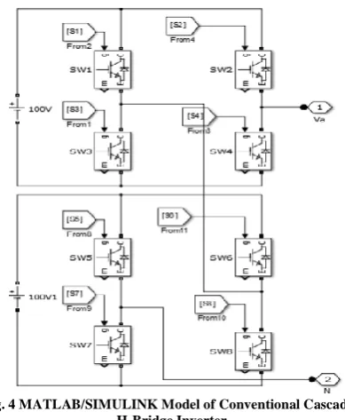
It should be noted that for n- level inverter topology, n-1/2 h bridges are required B. Harish et al., 2014); (D. Subramanian et al., 2013). Thus, for 5- level, 2 h bridges (8 switches) will be required as shown in Fig.
4. The h bridges are cascaded such that its output voltage will be addition of separate dc sources applied. There can be 5 possible levels at output including 2V, V, 0, -V, -2V. Due to separate dc sources required, this topology is suitable for utilizing energy from solar panels and fuel cells.
Fig. 4 MATLAB/SIMULINK Model of Conventional Cascaded H-Bridge Inverter
Level shifted SPWM (IPD, POD and APOD) are applied to control this topology having resistive load (20 Ω) and its simulations results are compared and analyzed below.
3.2 Five Level IPD PWM Technique
It should be noted that fundamental frequency of 50 Hz, Switching Frequency of 1 KHz and Modulation Index of 1 is taken. Fig. 5 shows the output voltage of topology using IPD and Fig. 6 represents total harmonic distortion of output voltage.
w w w . i j m r e t . o r g I S S N : 2 4 5 6 - 5 6 2 8
Page 27
Fig. 6 Output voltage FFT analysis with m=1 and Fswitching=1000Hz
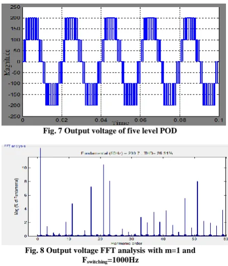
3.3 Five Level POD PWM Technique:
All the parameters are taken same as were taken for IPD PWM technique. Fig. 7 shows the output voltage of topology using POD and Fig. 8 represents total harmonic distortion of output voltage.
Fig. 7 Output voltage of five level POD
Fig. 8 Output voltage FFT analysis with m=1 and Fswitching=1000Hz
3.4 Five Level APOD PWM Technique:
All the parameters are taken same as were taken for IPD PWM and POD techniques. Fig. 9 shows the output voltage of topology using APOD and Fig. 10 represents total harmonic distortion of output voltage.
Fig. 9 Output voltage of five level APOD
Fig. 10 Output voltage FFT analysis with m=1 and Fswitching=1000Hz
3.5 Comparative analysis among IPD, POD and APOD PWM at different Modulation Index
It is concluded from Table 1. That %THD is almost same for all level shifted PWM techniques but it is slightly lower in POD as compared to IPD and APOD. Also, it is concluded from the obtained results that increasing the modulation index decreases the total harmonic distortion.
Table 1: Comparative analysis between Level Shifted SPWM for five levels
Ma IPD THD
(%)
POD THD
(%)
APOD
THD (%)
1 27.47% 26.91% 28.44%
0.9 34.01% 33.78% 33.91%
0.8 39.00% 38.55% 38.73%
0.7 42.51% 42.24% 43.08%
0.6 44.81% 44.15% 45.51%
3.6 Simulation Results of Modified Cascaded
w w w . i j m r e t . o r g I S S N : 2 4 5 6 - 5 6 2 8
Page 28
Fig. 11 MATLAB/SIMULINK Model of Modified Cascaded H-Bridge Inverter
Fig. 12 shows proposed IPD PWM technique for modified five levels topology, similarly POD and APOD PWM techniques can be designed with slight changes in values of triangular wave.
Fig. 12 Proposed IPD PWM Technique for Modified 5 level Topology
Level shifted SPWM (IPD, POD and APOD) are applied to control this topology, all the parameters are kept same as for conventional cascaded h bridge inverter due to comparison purpose.
3.7 Five Level IPD PWM Technique
Fig. 13 shows output voltage of five levels IPD PWM technique implemented on modified five levels topology and Fig. 14 shows output voltage total harmonics distortions.
Fig. 13 Output voltage of five level IPD
Fig. 14 Output voltage FFT analysis with m=1 and Fswitching=1000Hz
3.8 Five Level POD PWM Technique
Fig. 15 shows output voltage of five levels POD PWM technique implemented on modified five levels topology and Fig. 16 shows output voltage total harmonics distortions.
Fig. 15 Output voltage of five level POD
Fig. 16 Output voltage FFT analysis with m=1 and Fswitching=1000Hz
3.9 Five Level APOD PWM Technique
Fig. 17 shows output voltage of five levels APOD PWM technique implemented on modified five levels topology and Fig. 18 shows output voltage total harmonics distortions.
w w w . i j m r e t . o r g I S S N : 2 4 5 6 - 5 6 2 8
Page 29
Fig. 18 Output voltage FFT analysis with m=1 and Fswitching=1000Hz
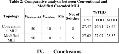
3.10 Comparative Analysis between Conventional
and Modified Five Level Inverter
It is concluded from the following table that modified multilevel inverter uses less number of switches, thus it has less switching complexity, low cost and reduced size of the system. Also, %THD of conventional and modified topologies is very close and there is veryslight difference. Therefore, modified multilevel inverter is considered to be better choice than conventional multilevel inverters.
Table 2: Comparative analysis between Conventional and Modified Cascaded MLI
Topology Ffundamental Fswitching Ma SwitchesNo: of
%THD
IPD POD APOD
Convention
al MLI 50 10 1 8
27.47 26.91 28.44
Modified
MLI 50 10 1 5
27.62 27.07 28.53
IV. Conclusions
It is observed that POD PWM technique has slightly less %THD than IPD and APOD in conventional as well modified MLI. Also, it is concluded that increasing Modulation Index (Ma) reduces %THD. Conventional and Modified MLI has almost same total harmonic distortions but Modified MLI uses only 5 switches whereas Conventional MLI uses 8 switches, hence switching complexity, switching losses and cost of the system is reduced and Modified MLI is recommended to be better choice.
V. Recommendations
Hardware Implementation
Digital PWM techniques can be implemented by using DSPs, Microcontrollers, Microprocessors, ASICs and FPGAs. These controllers can be compared and appropriate controller can be suggested for various applications.
Implementation using Phil lab
The hardware results using software laboratory which will save our cost and give validf results
Space Vector PWM
In future days, we will use space vector technique and we can compare its output with the sinusoidal PWM technique.
References
[1] B.L Nayak, G. Venkataratnam “ THD and Switching losses Analysis of Multi-Level Inverter Fed 3- Φ Induction Motor Drive”, International Journal of Scientific and Engineering Research, Vol. 5, issue 1,pp 2067-2074”
[2] E. Beser, B. Arifoglu, S. Camur and E.K Beser “Design and Application of a Single Phase Multilevel Inverter Suitable for using as Voltage Harmonic Source”, Journal of Power Electronics, Vol. 10, No. 2, March 2010.
[3] Y.M Park, H.S Ryu, H.Y Lee, M.G Jung and S.H Lee “Design of Cascaded H-Bridge Multilevel Inverter based on Power Electronics building blocks and control for High Performance”, Journal of Power Electronics, Vol. 10, No. 3, May 2010.
[4] S. Kouro, K. Gopakumar, J. Pou “Recent Advances and Industrial Applications of Multilevel Converters”, IEEE transaction on Industrial Electronics, Vol. 57, No. 8, August 2010.
[5] P.V Kumar, C.S Kumar and K.R Reddy “ Single Phase Cascaded Multilevel Inverter using Multicarrier PWM Technique”, ARPN Journal of Engineering and Applied Sciences, Vol. 8, No. 10, October 2013.
[6] R.A Ahmed, S. Mekhilef and H.W Ping “New Multilevel inverter topology with minimum number of switches”, Proc. IEEE, TENCON 2010, 1862-1867.
[7] G. Varghese, T. Tom and J.K Sajev “ Comparison between Conventional and Modified Cascaded H-Bridge Multilevel Inverter-Fed Drive”, International Journal of Innovative Research in Electrical, Electronics, Instrumentation and Control Engineering, Vol. 10, Issue. 9, September 2015.
w w w . i j m r e t . o r g I S S N : 2 4 5 6 - 5 6 2 8
Page 30
and Instrumentation Engineering, Vol. 3, Issue. 2, Feb 2014.
[9] D. Subramanian, R. Rasheed “ Modified Multilevel Inverter Topology for Driving a single phase induction motor”, International Journal of Advanced Research in Electrical, Electronics and Instrumentation Engineering, Vol. 2, Issue. 1, Dec 2013.